ZyXEL Communications XGS-4528F User Manual
Intelligent layer 3+ switch
Hide thumbs
Also See for XGS-4528F:
- User manual (434 pages) ,
- Specifications (2 pages) ,
- Quick start manual (43 pages)

Related Manuals for ZyXEL Communications XGS-4528F


Summary of Contents for ZyXEL Communications XGS-4528F
- Page 1 XGS-4528F Intelligent Layer 3+ Switch User’s Guide Version 3.80 8/2007 Edition 1 DEFAULT LOGIN IP Address http://192.168.1.1 User Name admin Password 1234 www.zyxel.com...
-
Page 3: About This User's Guide
About This User's Guide Intended Audience This manual is intended for people who want to configure the Switch using the web configurator or via commands. You should have at least a basic knowledge of TCP/IP networking concepts and topology. Related Documentation •... -
Page 4: Document Conventions
Syntax Conventions • The XGS-4528F may be referred to as the “Switch”, the “device”, the “system” or the “product” in this User’s Guide. • Product labels, screen names, field labels and field choices are all in bold font. - Page 5 Icons Used in Figures Figures in this User’s Guide may use the following generic icons. The Switch icon is not an exact representation of your device. The Switch Server Telephone XGS-4528F User’s Guide Computer Notebook computer DSLAM Firewall Switch Router...
-
Page 6: Safety Warnings
• Do not use the device outside, and make sure all the connections are indoors. There is a remote risk of electric shock from lightning. • Do NOT obstruct the device ventilation slots, as insufficient airflow may harm your device. Safety Warnings XGS-4528F User’s Guide... - Page 7 Safety Warnings This product is recyclable. Dispose of it properly. XGS-4528F User’s Guide...
- Page 8 Safety Warnings XGS-4528F User’s Guide...
-
Page 9: Table Of Contents
Authentication & Accounting ... 187 IP Source Guard ... 201 Loop Guard ... 221 IP Application ... 225 Static Route ... 227 RIP ... 229 OSPF ... 231 IGMP ... 243 DVMRP ... 247 XGS-4528F User’s Guide Contents Overview Contents Overview... - Page 10 MAC Table ... 315 IP Table ... 317 ARP Table ... 319 Routing Table ... 321 Configure Clone ... 323 Troubleshooting & Product Specifications ... 325 Troubleshooting ... 327 Product Specifications ... 335 Appendices and Index ... 343 XGS-4528F User’s Guide...
-
Page 11: Table Of Contents
2.1 Freestanding Installation ... 39 2.2 Mounting the Switch on a Rack ... 40 2.2.1 Rack-mounted Installation Requirements ... 40 2.2.2 Attaching the Mounting Brackets to the Switch ... 40 2.2.3 Mounting the Switch on a Rack ... 41 Chapter 3 Hardware Overview... - Page 12 6.1 Overview ... 67 6.2 Port Status Summary 6.2.1 Status: Port Details Chapter 7 Basic Setting ... 73 7.1 Overview ... 73 7.2 System Information ... 52 ... 58 ... 59 ... 67 ... 68 ... 73 XGS-4528F User’s Guide...
- Page 13 9.1 Overview ... 103 9.2 Configuring Static MAC Forwarding Chapter 10 Filtering... 105 10.1 Configure a Filtering Rule Chapter 11 Spanning Tree Protocol... 107 XGS-4528F User’s Guide ... 77 ... 87 ... 91 ... 92 ... 97 ... 99 ... 103 ...
- Page 14 15.6 Static Trunking Example ... 138 Chapter 16 Port Authentication... 141 16.1 Port Authentication Overview ... 141 16.1.1 IEEE 802.1x Authentication ... 141 ... 107 ... 109 ...114 ...116 ...117 ...119 ... 120 ... 123 ... 127 ... 136 XGS-4528F User’s Guide...
- Page 15 21.1 VLAN Stacking Overview ... 167 21.1.1 VLAN Stacking Example ... 167 21.2 VLAN Stacking Port Roles ... 168 21.3 VLAN Tag Format ... 169 21.3.1 Frame Format ... 169 21.4 Configuring VLAN Stacking ... 170 XGS-4528F User’s Guide ... 143 Table of Contents...
- Page 16 24.1.2 ARP Inspection Overview ... 203 24.2 IP Source Guard ... 205 24.3 IP Source Guard Static Binding ... 205 24.4 DHCP Snooping ... 207 24.5 DHCP Snooping Configure ... 210 ... 188 ... 190 ... 192 XGS-4528F User’s Guide...
- Page 17 28.3 OSPF Configuration ... 235 28.4 Configure OSPF Areas ... 237 28.4.1 View OSPF Area Information Table ... 238 28.5 Configuring OSPF Interfaces 28.6 OSPF Virtual-Links Chapter 29 IGMP... 243 XGS-4528F User’s Guide ... 238 ... 240 Table of Contents...
- Page 18 32.4.2 Configuring DHCP Global Relay ... 262 32.4.3 Global DHCP Relay Configuration Example ... 263 32.5 Configuring DHCP VLAN Settings 32.5.1 Example: DHCP Relay for Two VLANs ... 266 Chapter 33 VRRP ... 267 ... 256 ... 264 XGS-4528F User’s Guide...
- Page 19 35.3.3 SNMP Traps ... 287 35.3.4 Configuring SNMP 35.3.5 Configuring SNMP Trap Group 35.3.6 Setting Up Login Accounts 35.4 SSH Overview ... 295 35.5 How SSH works ... 295 XGS-4528F User’s Guide ... 281 ... 282 ... 282 ... 285 ... 287 ...
- Page 20 40.1 IP Table Overview ... 317 40.2 Viewing the IP Table ... 318 Chapter 41 ARP Table ... 319 41.1 ARP Table Overview ... 319 41.1.1 How ARP Works ... 319 41.2 Viewing the ARP Table ... 319 ... 299 ... 300 XGS-4528F User’s Guide...
- Page 21 Chapter 45 Product Specifications ... 335 Part VII: Appendices and Index ... 343 Appendix A IP Addresses and Subnetting ... 345 Appendix B Legal Information ... 353 Appendix C Customer Support... 357 Index... 363 XGS-4528F User’s Guide Table of Contents...
- Page 22 Table of Contents XGS-4528F User’s Guide...
-
Page 23: List Of Figures
Figure 16 Web Configurator Home Screen (Status) ... 52 Figure 17 Change Administrator Login Password ... 58 Figure 18 Resetting the Switch: Via the Console Port ... 60 Figure 19 Web Configurator: Logout Screen ... 60 Figure 20 Initial Setup Network Example: IP Interface ... 61 Figure 21 Initial Setup Network Example: VLAN ... - Page 24 Figure 77 Policy Example ... 161 Figure 78 Advanced Application > Queuing Method ... 164 Figure 79 VLAN Stacking Example ... 168 Figure 80 Advanced Application > VLAN Stacking ... 170 Figure 81 Advanced Application > Multicast ... 174 XGS-4528F User’s Guide...
- Page 25 Figure 121 IP Application > OSPF Status ... 234 Figure 122 IP Application > OSPF Configuration: Activating and General Settings ... 236 Figure 123 IP Application > OSPF Configuration: Area Setup ... 237 Figure 124 IP Application > OSPF Configuration: Summary Table ... 238 XGS-4528F User’s Guide...
- Page 26 Figure 162 VRRP Configuration Example: Two Virtual Router Network ... 274 Figure 163 VRRP Example 2: VRRP Parameter Settings for VR2 on Switch A ... 274 Figure 164 VRRP Example 2: VRRP Parameter Settings for VR2 on Switch B ... 274 Figure 165 VRRP Example 2: VRRP Status on Switch A ...
- Page 27 Figure 191 Management > Cluster Management ... 310 Figure 192 Cluster Management: Cluster Member Web Configurator Screen ...311 Figure 193 Example: Uploading Firmware to a Cluster Member Switch ... 312 Figure 194 Management > Clustering Management > Configuration ... 313 Figure 195 MAC Table Flowchart ...
- Page 28 List of Figures Figure 211 Subnetting Example: Before Subnetting ... 348 Figure 212 Subnetting Example: After Subnetting ... 349 XGS-4528F User’s Guide...
-
Page 29: List Of Tables
Table 9 Basic Setting > System Info ... 74 Table 10 Basic Setting > General Setup ... 75 Table 11 Basic Setting > Switch Setup ... 78 Table 12 Basic Setting > IP Setup ... 80 Table 13 Basic Setting > Port Setup ... 82 Table 14 IEEE 802.1Q VLAN Terminology ... - Page 30 Table 77 ARP Inspection VLAN Status ... 215 Table 78 ARP Inspection Log Status ... 216 Table 79 ARP Inspection Configure ... 217 Table 80 ARP Inspection Port Configure ... 219 Table 81 ARP Inspection VLAN Configure ... 220 XGS-4528F User’s Guide...
- Page 31 Table 121 Management > Access Control > SNMP > Trap Group ... 293 Table 122 Management > Access Control > Logins ... 294 Table 123 Management > Access Control > Service Access Control ... 300 Table 124 Management > Access Control > Remote Management ... 300 XGS-4528F User’s Guide...
- Page 32 Table 136 Management > Routing Table ... 321 Table 137 Management > Configure Clone ... 324 Table 138 Troubleshooting the Start-Up of Your Switch ... 327 Table 139 Troubleshooting Accessing the Switch ... 327 Table 140 Troubleshooting the Password ... 333 Table 141 Hardware Specifications ...
-
Page 33: Introduction
Introduction Getting to Know Your Switch (35) Hardware Installation and Connection (39) Hardware Overview (43) -
Page 35: Getting To Know Your Switch
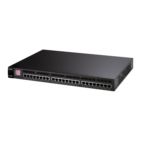
There are two XGS-4528F models. The XGS-4528F DC model requires DC power supply input of -36 VDC to -72 VDC, 1.5 A Max no tolerance. The XGS-4528F AC model requires 100 VAC to 240 VAC, 0.8 A power. -
Page 36: High Performance Switching Example
Figure 1 Bridging Application 1.1.2 High Performance Switching Example The Switch is ideal for connecting two geographically dispersed networks that need high bandwidth. In the following example, a company uses the optional 10 Gigabit uplink modules to connect the headquarters to a branch office network. Within the headquarters network, a company can use trunking to group several physical ports into one logical higher-capacity link. -
Page 37: Gigabit Ethernet To The Desktop
1.1.3 Gigabit Ethernet to the Desktop The Switch is an ideal solution for small networks which demand high bandwidth for a group of heavy traffic users. You can connect computers and servers directly to the Switch’s port or connect other switches to the Switch. Use the optional 10 Gigabit uplink module to provide high speed access to a data server and the Internet. -
Page 38: Ways To Manage The Switch
286. 1.3 Good Habits for Managing the Switch Do the following things regularly to make the Switch more secure and to manage the Switch more effectively. • Change the password. Use a password that’s not easy to guess and that consists of different types of characters, such as numbers and letters. -
Page 39: Hardware Installation And Connection
4 Remove the adhesive backing from the rubber feet. 5 Attach the rubber feet to each corner on the bottom of the Switch. These rubber feet help protect the Switch from shock or vibration and ensure space between devices when stacking. -
Page 40: Mounting The Switch On A Rack
2.2.2 Attaching the Mounting Brackets to the Switch 1 Position a mounting bracket on one side of the Switch, lining up the four screw holes on the bracket with the screw holes on the side of the Switch. -
Page 41: Mounting The Switch On A Rack
2.2.3 Mounting the Switch on a Rack 1 Position a mounting bracket (that is already attached to the Switch) on one side of the rack, lining up the two screw holes on the bracket with the screw holes on the side of the rack. - Page 42 Chapter 2 Hardware Installation and Connection XGS-4528F User’s Guide...
-
Page 43: Hardware Overview
H A P T E R This chapter describes the front panel and rear panel of the Switch and shows you how to make the hardware connections. 3.1 Front Panel Connections The figure below shows the front panel of the Switch. -
Page 44: 1000Base-T Ports
Use a transceiver to connect a fiber-optic cable to the Switch. The Switch does not come with transceivers. You must use transceivers that comply with the Small Form-Factor Pluggable (SFP) Transceiver MultiSource Agreement (MSA). -
Page 45: Figure 9 Transceiver Installation Example
Figure 9 Transceiver Installation Example 2 Press the transceiver firmly until it clicks into place. 3 The Switch automatically detects the installed transceiver. Check the LEDs to verify that it is functioning properly. Figure 10 Installed Transceiver 3.1.3.2 Transceiver Removal Use the following steps to remove a mini GBIC transceiver (SFP module). -
Page 46: Rear Panel
See the EM-422 User’s Guide for more information on this module. Two stacking Connect these ports to other XGS-4528F switches for stacking using stacking cables. ports Management Connect to a computer using an RJ-45 Ethernet cable for local configuration of the Port Switch. -
Page 47: Power Connector
Make sure that no objects obstruct the airflow of the fans. The Switch’s AC unit requires a power supply of 100~240 VAC, 0.8 A. The Switch’s DC version requires a power supply of -48 VDC to -60 VDC, 2.3 A max, no tolerance. - Page 48 The Switch is connected to other switches in the stack on Stacking Port 1. The Switch is not connected to other switches in the stack on Stacking Port 1. The Switch is connected to other switches in the stack on Stacking Port 2.
-
Page 49: Basic Configuration
Basic Configuration The Web Configurator (51) Initial Setup Example (61) System Status and Port Statistics (67) Basic Setting (73) -
Page 51: The Web Configurator
4.2 System Login 1 Start your web browser. 2 Type “http://” and the IP address of the Switch (for example, the default is 192.168.1.1) in the Location or Address field. Press [ENTER]. 3 The login screen appears. The default username is admin and associated default password is 1234. -
Page 52: The Status Screen
The following figure shows the navigating components of a web configurator screen. Figure 16 Web Configurator Home Screen (Status) A - Click the menu items to open submenu links, and then click on a submenu link to open the screen in the main window. XGS-4528F User’s Guide... -
Page 53: Table 4 Navigation Panel Sub-Links Overview
B - Click this link to save your configuration into the Switch’s nonvolatile memory. Nonvolatile memory is saved in the configuration file from which the Switch booted from and it stays the same even if the Switch’s power is turned off. See information on saving your settings to a specific configuration file. - Page 54 Chapter 4 The Web Configurator The following table lists the various web configurator screens within the sub-links. XGS-4528F User’s Guide...
-
Page 55: Table 5 Web Configurator Screen Sub-Links Details
- ARP Inspection VLAN Status - ARP Inspection Log Status - ARP Inspection Configure -- ARP Inspection Port Configure -- ARP Inspection VLAN Configure Loop Guard XGS-4528F User’s Guide Chapter 4 The Web Configurator IP APPLICATION MANAGEMENT Static Routing Maintenance Firmware Upgrade Restore Configuration... -
Page 56: Table 6 Navigation Panel Links
This link takes you to a screen where you can configure general identification information and time settings for the Switch. Switch Setup This link takes you to a screen where you can set up global Switch parameters such as VLAN type, MAC address learning, IGMP snooping, GARP and priority queues. - Page 57 Static Route This link takes you to a screen where you can configure static routes. A static route defines how the Switch should forward traffic by configuring the TCP/IP parameters manually. This link takes you to a screen where you can configure the RIP (Routing Information Protocol) direction and versions.
-
Page 58: Change Your Password
4.4 Saving Your Configuration When you are done modifying the settings in a screen, click Apply to save your changes back to the run-time memory. Settings in the run-time memory are lost when the Switch’s power is turned off. Click the Save link in the upper right hand corner of the web configurator to save your configuration to nonvolatile memory. -
Page 59: Resetting The Switch
7 Prevent all services from accessing the Switch. 8 Change a service port number but forget it. Be careful not to lock yourself and others out of the Switch. If you do lock yourself out, try using out-of-band management (via the management port) to configure the Switch. -
Page 60: Logging Out Of The Web Configurator
393216 bytes received. Erasing.. ras> atgo The Switch is now reinitialized with a default configuration file including the default password of “1234”. 4.7 Logging Out of the Web Configurator Click Logout in a screen to exit the web configurator. You have to log in with your password again after you log out. -
Page 61: Initial Setup Example
5.1.1 Configuring an IP Interface On a layer-3 switch, an IP interface (also known as an IP routing domain) is not bound to a physical port. The default IP address of the Switch is 192.168.1.1 with a subnet mask of 255.255.255.0. -
Page 62: Configuring Dhcp Server Settings
5.1.2 Configuring DHCP Server Settings You can set the Switch to assign network information (such as the IP address, DNS server, etc.) to DHCP clients on the network. For the example network, configure two DHCP client pools on the Switch for the DHCP clients in the RD and Sales networks. -
Page 63: Creating A Vlan
VLAN link. 2 In the Static VLAN screen, select ACTIVE, enter a descriptive name in the Name field and enter 2 in the VLAN Group ID field for the VLAN2 network. XGS-4528F User’s Guide Chapter 5 Initial Setup Example EXAMPLE... -
Page 64: Setting Port Vid
The VLAN Group ID field in this screen and the VID field in the IP Setup screen refer to the same VLAN ID. 3 Since the VLAN2 network is connected to port 1 on the Switch, select Fixed to configure port 1 to be a permanent member of the VLAN only. -
Page 65: Enabling Rip
4 Click Apply to save your changes back to the run-time memory. Settings in the run-time memory are lost when the Switch’s power is turned off. XGS-4528F User’s Guide Chapter 5 Initial Setup Example EXAMPLE... - Page 66 Chapter 5 Initial Setup Example XGS-4528F User’s Guide...
-
Page 67: System Status And Port Statistics
The home screen of the web configurator displays a port statistical summary with links to each port showing statistical details. 6.2 Port Status Summary To view the port statistics, click Status in all web configurator screens to display the Status screen as shown next. Figure 23 Status XGS-4528F User’s Guide Statistics... -
Page 68: Status: Port Details
Click a number in the Port column in the Status screen to display individual port statistics. Use this screen to check status and detailed performance data about an individual port on the Switch. Figure 24 on page 69). Section 11.1.3 on page 108 for more information). XGS-4528F User’s Guide... -
Page 69: Figure 24 Status: Port Details
This field shows the number of received errors on this port. Tx KB/s This field shows the transmission speed of data sent on this port in kilobytes per second. XGS-4528F User’s Guide Chapter 6 System Status and Port Statistics for more information). - Page 70 This field shows the number of packets (including bad packets) received that were between 65 and 127 octets in length. 128-255 This field shows the number of packets (including bad packets) received that were between 128 and 255 octets in length. XGS-4528F User’s Guide...
- Page 71 This field shows the number of packets (including bad packets) received that were 1518 between 1024 and 1518 octets in length. Giant This field shows the number of packets dropped because they were bigger than the maximum frame size. XGS-4528F User’s Guide Chapter 6 System Status and Port Statistics...
- Page 72 Chapter 6 System Status and Port Statistics XGS-4528F User’s Guide...
-
Page 73: Basic Setting
Switch. The real time is then displayed in the Switch logs. The Switch Setup screen allows you to set up and configure global Switch features. The IP Setup screen allows you to configure a Switch IP address in each routing domain, subnet mask(s) and DNS (domain name server) for management purposes. -
Page 74: Figure 25 Basic Setting > System Info
DESCRIPTION System Name This field displays the descriptive name of the Switch for identification purposes. ZyNOS F/W This field displays the version number of the Switch 's current firmware including the Version date created. Ethernet This field refers to the Ethernet MAC (Media Access Control) address of the Switch. -
Page 75: General Setup
Type a descriptive name for identification purposes. This name consists of up to 64 printable characters; spaces are allowed. Location Type the geographic location of your Switch. You can use up to 32 printable ASCII characters; spaces are allowed. XGS-4528F User’s Guide... - Page 76 Table 10 Basic Setting > General Setup (continued) LABEL DESCRIPTION Contact Person's Type the name of the person in charge of this Switch. You can use up to 32 Name printable ASCII characters; spaces are allowed. Use Time Server Type the time service protocol that your timeserver uses. Not all time servers...
-
Page 77: Introduction To Vlans
Chapter 8 on page 87 7.5 Switch Setup Screen Click Basic Setting and then Switch Setup in the navigation panel to display the screen as shown. The VLAN setup screens change depending on whether you choose 802.1Q or Port Based in the VLAN Type field in this screen. Refer to the chapter on VLAN. -
Page 78: Figure 27 Basic Setting > Switch Setup
802.1Q VLAN type or Port Based VLAN type in this screen. Bridge Control Select Active to allow the Switch to handle bridging control protocols (STP, for Protocol example). You also need to define how to treat a BPDU in the Port Setup screen. -
Page 79: Ip Setup
Use the following fields to configure the priority level-to-physical queue mapping. The Switch has eight physical queues that you can map to the 8 priority levels. On the Switch, traffic assigned to higher index queues gets through faster while traffic in lower index queues is dropped if the network is congested. -
Page 80: Figure 28 Basic Setting > Ip Setup
MGMT. This means that device(s) connected to the other port(s) do not receive these packets. Select In-Band to have the Switch send the packets to all ports except the management port (labelled MGMT) to which connected device(s) do not receive these packets. -
Page 81: Port Setup
Cancel Click Cancel to clear the Delete check boxes. 7.7 Port Setup Use this screen to configure Switch port settings.Click Basic Setting > Port Setup in the navigation panel to display the configuration screen. XGS-4528F User’s Guide Chapter 7 Basic Setting... -
Page 82: Figure 29 Basic Setting > Port Setup
Note: Due to space limitations, the port name may be truncated in Type This field displays 10/100/1000M for a 1000Base-T connection and 10G for a 10 Gigabit Ethernet connection. make them. some web configurator screens. XGS-4528F User’s Guide... - Page 83 Selecting Auto (auto-negotiation) allows one port to negotiate with a peer port automatically to obtain the connection speed and duplex mode that both ends support. When auto-negotiation is turned on, a port on the Switch negotiates with the peer automatically to determine the connection speed and duplex mode. If the peer...
- Page 84 Chapter 7 Basic Setting XGS-4528F User’s Guide...
-
Page 85: Advanced Setup
Advanced Setup VLAN (87) Static MAC Forward Setup (103) Filtering (105) Spanning Tree Protocol (107) Bandwidth Control (127) Broadcast Storm Control (129) Mirroring (131) Link Aggregation (133) Port Authentication (141) Port Security (147) Classifier (151) Policy Rule (157) Queuing Method (163) VLAN Stacking (167) Multicast (173) Authentication &... -
Page 87: Vlan
H A P T E R The type of screen you see here depends on the VLAN Type you selected in the Switch Setup screen. This chapter shows you how to configure 802.1Q tagged and port-based VLANs. 8.1 Introduction to IEEE 802.1Q Tagged VLANs... -
Page 88: Automatic Vlan Registration
GVRP (GARP VLAN Registration Protocol) is a registration protocol that defines a way for switches to register necessary VLAN members on ports across the network. Enable this function to permit VLAN groups beyond the local Switch. Please refer to the following table for common IEEE 802.1Q VLAN terminology. -
Page 89: Port Vlan Trunking
VLAN group tags. However, with VLAN Trunking enabled on a port(s) in each intermediary switch you only need to create VLAN groups in the end devices (A and B). C, D and E automatically allow frames with VLAN group tags 1 and 2 (VLAN groups that are unknown to those switches) to pass through their VLAN trunking port(s). -
Page 90: Static Vlan Status
VLAN was set up. Status This field shows how this VLAN was added to the Switch; dynamic - using GVRP, static - added as a permanent entry or other - added in another way such as via Multicast VLAN Registration (MVR). -
Page 91: Configure A Static Vlan
VLAN was set up. Status This field shows how this VLAN was added to the Switch; dynamic - using GVRP, static - added as a permanent entry or other - added in another way such as via Multicast VLAN Registration (MVR). -
Page 92: Configure Vlan Port Settings
Select TX Tagging if you want the port to tag all outgoing frames transmitted with this VLAN Group ID. Click Add to save your changes to the Switch’s run-time memory. The Switch loses these changes if it is turned off or loses power, so use the Save link on the top navigation panel to save your changes to the non-volatile memory when you are done configuring. -
Page 93: Figure 35 Advanced Application > Vlan > Vlan Port Setting
Note: Changes in this row are copied to all the ports as soon as you Ingress Check If this check box is selected for a port, the Switch discards incoming frames for VLANs that do not include this port in its member set. -
Page 94: Subnet Based Vlans
Subnet based VLANs allow you to group traffic into logical VLANs based on the source IP subnet you specify. When a frame is received on a port, the Switch checks if a tag is added already and the IP subnet it came from. The untagged packets from the same IP subnet are then placed in the same subnet based VLAN. -
Page 95: Configuring Subnet Based Vlan
DHCP VLAN. Apply Click Apply to save your changes to the Switch’s run-time memory. The Switch loses these changes if it is turned off or loses power, so use the Save link on the top navigation panel to save your changes to the non-volatile memory when you are done configuring. -
Page 96: Protocol Based Vlans
When an upstream frame is received on a port (configured for a protocol based VLAN), the Switch checks if a tag is added already and its protocol. The untagged packets of the same protocol are then placed in the same protocol based VLAN. One advantage of using protocol based VLANs is that priority can be assigned to traffic of the same protocol. -
Page 97: Configuring Protocol Based Vlan
8.9 Configuring Protocol Based VLAN Click Protocol Based VLAN in the VLAN Port Setting screen to display the configuration screen as shown. Figure 39 Advanced Application > VLAN > VLAN Port Setting > Protocol Based VLAN XGS-4528F User’s Guide Chapter 8 VLAN... -
Page 98: Create An Ip-Based Vlan Example
Advanced Applications > VLAN screens. Priority Select the priority level that the Switch will assign to frames belonging to this VLAN. Click Add to save your changes to the Switch’s run-time memory. The Switch loses... -
Page 99: Port-Based Vlan Setup
Port-based VLANs are specific only to the Switch on which they were created. When you activate port-based VLAN, the Switch uses a default VLAN ID of 1. You cannot change it. -
Page 100: Configure A Port-Based Vlan
Ethernet ports. 8.11.1 Configure a Port-based VLAN Select Port Based as the VLAN Type in the Switch Setup screen and then click VLAN from the navigation panel to display the following screen. Select either All Connected or Port Isolated from the drop-down list depending on your VLAN and VLAN security requirements. -
Page 101: Figure 42 Advanced Application > Vlan: Port Based Vlan Setup (Port Isolation)
Chapter 8 VLAN Figure 42 Advanced Application > VLAN: Port Based VLAN Setup (Port Isolation) XGS-4528F User’s Guide... -
Page 102: Table 21 Advanced Application > Vlan: Port Based Vlan Setup
(its outgoing port). CPU refers to the Switch management port. By default it forms a VLAN with all Ethernet ports. If it does not form a VLAN with a particular port then the Switch cannot be managed from that port. -
Page 103: Static Mac Forward Setup
MAC addresses for a port. This may reduce the need for broadcasting. Static MAC address forwarding together with port security allows only computers in the MAC address table on a port to access the Switch. See on port security. -
Page 104: Table 22 Advanced Application > Static Mac Forwarding
Enter the port where the MAC address entered in the previous field will be automatically forwarded. Click Add to save your rule to the Switch’s run-time memory. The Switch loses this rule if it is turned off or loses power, so use the Save link on the top navigation panel to save your changes to the non-volatile memory when you are done configuring. -
Page 105: Filtering
This chapter discusses MAC address port filtering. 10.1 Configure a Filtering Rule Configure the Switch to filter traffic based on the traffic’s source, destination MAC addresses and/or VLAN group (ID). Click Advanced Application > Filtering in the navigation panel to display the screen as shown next. - Page 106 MAC field). The Switch can still send frames to the MAC address. Select Discard destination to drop frames to the destination MAC address (specified in the MAC address). The Switch can still receive frames originating from the MAC address. Select Discard source and Discard destination to block traffic to/from the MAC address specified in the MAC field.
-
Page 107: Spanning Tree Protocol
• IEEE 802.1D Spanning Tree Protocol • IEEE 802.1w Rapid Spanning Tree Protocol • IEEE 802.1s Multiple Spanning Tree Protocol The Switch also allows you to set up multiple STP configurations (or trees). Ports can then be assigned to the trees. 11.1 STP/RSTP Overview (R)STP detects and breaks network loops and provides backup links between switches, bridges or routers. -
Page 108: How Stp Works
On each bridge, the bridge communicates with the root through the root port. The root port is the port on this Switch with the lowest path cost to the root (the root path cost). If there is no root port, then this Switch has been accepted as the root bridge of the spanning tree network. -
Page 109: Multiple Rstp
MRSTP (Multiple RSTP) is ZyXEL’s proprietary feature that is compatible with RSTP and STP. With MRSTP, you can have more than one spanning tree on your Switch and assign port(s) to each tree. Each spanning tree operates independently with its own bridge information. -
Page 110: Figure 46 Stp/Rstp Network Example
VLAN 1 With MSTP, VLANs 1 and 2 are mapped to different spanning trees in the network. Thus traffic from the two VLANs travel on different paths. The following figure shows the network example using MSTP. VLAN 2 XGS-4528F User’s Guide... -
Page 111: Figure 47 Mstp Network Example
Thus an MSTI does not span across MST regions. The following figure shows an example where there are two MST regions. Regions 1 and 2 have 2 spanning tree instances. XGS-4528F User’s Guide Chapter 11 Spanning Tree Protocol VLAN 2... -
Page 112: Spanning Tree Protocol Status Screen
11.2 Spanning Tree Protocol Status Screen The Spanning Tree Protocol status screen changes depending on what standard you choose to implement on your network. Click Advanced Application > Spanning Tree Protocol to see the screen as shown. XGS-4528F User’s Guide... -
Page 113: Spanning Tree Configuration
This screen differs depending on which STP mode (RSTP, MRSTP or MSTP) you configure on the Switch. This screen is described in detail in the section that follows the configuration section for each STP mode. Click Configuration to activate one of the STP standards on the Switch. -
Page 114: Configure Rapid Spanning Tree Protocol
Select this check box to activate RSTP. Clear this checkbox to disable RSTP. Note: You must also activate Rapid Spanning Tree in the Advanced Application > Spanning Tree Protocol > Configuration screen to enable RSTP on the Switch. for more information Figure 53 on page 116). XGS-4528F User’s Guide... - Page 115 (provided in the last BPDU) becomes the designated port for the attached LAN. If it is a root port, a new root port is selected from among the switch ports attached to the network. The allowed range is 6 to 40 seconds.
-
Page 116: Rapid Spanning Tree Protocol Status
Switch. This Switch may also be the root bridge. This is the unique identifier for this bridge, consisting of the bridge priority plus the MAC address. This ID is the same for Root and Our Bridge if the Switch is the root switch. -
Page 117: Configure Multiple Rapid Spanning Tree Protocol
Select this check box to activate an STP tree. Clear this checkbox to disable an STP tree. Note: You must also activate Multiple Rapid Spanning Tree in the XGS-4528F User’s Guide Chapter 11 Spanning Tree Protocol for more information on MRSTP. - Page 118 (provided in the last BPDU) becomes the designated port for the attached LAN. If it is a root port, a new root port is selected from among the Switch ports attached to the network. The allowed range is 6 to 40 seconds.
-
Page 119: Multiple Rapid Spanning Tree Protocol Status
Switch. This Switch may also be the root bridge. Bridge ID This is the unique identifier for this bridge, consisting of bridge priority plus MAC address. This ID is the same for Root and Our Bridge if the Switch is the root switch. Hello Time... -
Page 120: Configure Multiple Spanning Tree Protocol
To configure MSTP, click MSTP in the Advanced Application > Spanning Tree Protocol screen. See Section 11.1.5 on page 109 DESCRIPTION This is the number of times the spanning tree has been reconfigured. This is the time since the spanning tree was last reconfigured. for more information on MSTP. XGS-4528F User’s Guide... -
Page 121: Figure 56 Advanced Application > Spanning Tree Protocol > Mstp
Chapter 11 Spanning Tree Protocol Figure 56 Advanced Application > Spanning Tree Protocol > MSTP XGS-4528F User’s Guide... -
Page 122: Table 31 Advanced Application > Spanning Tree Protocol > Mstp
(provided in the last BPDU) becomes the designated port for the attached LAN. If it is a root port, a new root port is selected from among the Switch ports attached to the network. The allowed range is 6 to 40 seconds. -
Page 123: Multiple Spanning Tree Protocol Status
Priority decides which port should be disabled when more than one port forms a loop in the Switch. Ports with a higher priority numeric value are disabled first. The allowed range is between 0 and 255 and the default value is 128. -
Page 124: Figure 57 Advanced Application > Spanning Tree Protocol > Status: Mstp
Switch. This Switch may also be the root bridge. This is the unique identifier for this bridge, consisting of bridge priority plus MAC address. This ID is the same for Root and Our Bridge if the Switch is the root switch. - Page 125 Switch may also be the root bridge. Bridge ID This is the unique identifier for this bridge, consisting of bridge priority plus MAC address. This ID is the same for Root and Our Bridge if the Switch is the root switch. Internal Cost This is the path cost from the root port in this MST instance to the regional root switch.
- Page 126 Chapter 11 Spanning Tree Protocol XGS-4528F User’s Guide...
-
Page 127: Bandwidth Control
The sum of CIRs cannot be greater than or equal to the uplink bandwidth. 12.2 Bandwidth Control Setup Click Advanced Application > Bandwidth Control in the navigation panel to bring up the screen as shown next. XGS-4528F User’s Guide Bandwidth Control... -
Page 128: Figure 58 Advanced Application > Bandwidth Control
Apply Click Apply to save your changes to the Switch’s run-time memory. The Switch loses these changes if it is turned off or loses power, so use the Save link on the top navigation panel to save your changes to the non-volatile memory when you are done configuring. -
Page 129: Broadcast Storm Control
13.1 Broadcast Storm Control Setup Broadcast storm control limits the number of broadcast, multicast and destination lookup failure (DLF) packets the Switch receives per second on the ports. When the maximum number of allowable broadcast, multicast and/or DLF packets is reached per second, the subsequent packets are discarded. -
Page 130: Table 34 Advanced Application > Broadcast Storm Control
Table 34 Advanced Application > Broadcast Storm Control LABEL DESCRIPTION Active Select this check box to enable traffic storm control on the Switch. Clear this check box to disable this feature. Port This field displays a port number. Settings in this row apply to all ports. -
Page 131: Mirroring
Click Advanced Application > Mirroring in the navigation panel to display the Mirroring screen. Use this screen to select a monitor port and specify the traffic flow to be copied to the monitor port. Figure 60 Advanced Application > Mirroring XGS-4528F User’s Guide Mirroring... -
Page 132: Table 35 Advanced Application > Mirroring
LABEL DESCRIPTION Active Select this check box to activate port mirroring on the Switch. Clear this check box to disable the feature. Monitor The monitor port is the port you copy the traffic to in order to examine it in more detail Port without interfering with the traffic flow on the original port(s). -
Page 133: Link Aggregation
Switch. Section 15.6 on page 138 15.2 Dynamic Link Aggregation The Switch adheres to the IEEE 802.3ad standard for static and dynamic (LACP) port trunking. The Switch supports the link aggregation IEEE802.3ad standard. This standard describes the Link Aggregation Control Protocol (LACP), which is a protocol that dynamically creates and manages trunk groups. -
Page 134: Link Aggregation Id
Chapter 15 Link Aggregation • You must connect all ports point-to-point to the same Ethernet switch and configure the ports for LACP trunking. • LACP only works on full-duplex links. • All ports in the same trunk group must have the same media type, speed, duplex mode and flow control settings. -
Page 135: Link Aggregation Setting
Click Advanced Application > Link Aggregation > Link Aggregation Setting to display the screen shown next. See aggregation. Figure 62 Advanced Application > Link Aggregation > Link Aggregation Setting XGS-4528F User’s Guide Section 15.2.1 on page 134 Section 15.1 on page 133 for more information on link... -
Page 136: Link Aggregation Control Protocol
Select the trunk group to which a port belongs. Apply Click Apply to save your changes to the Switch’s run-time memory. The Switch loses these changes if it is turned off or loses power, so use the Save link on the top navigation panel to save your changes to the non-volatile memory when you are done configuring. -
Page 137: Figure 63 Advanced Application > Link Aggregation > Link Aggregation Setting > Lacp
Select this checkbox to enable Link Aggregation Control Protocol (LACP). System LACP system priority is a number between 1 and 65,535. The switch with the lowest Priority system priority (and lowest port number if system priority is the same) becomes the LACP “server”. -
Page 138: Static Trunking Example
Select either 1 second or 30 seconds. Apply Click Apply to save your changes to the Switch’s run-time memory. The Switch loses these changes if it is turned off or loses power, so use the Save link on the top navigation panel to save your changes to the non-volatile memory when you are done configuring. -
Page 139: Figure 65 Trunking Example - Configuration Screen
Chapter 15 Link Aggregation Figure 65 Trunking Example - Configuration Screen EXAMPLE Your trunk group 1 (T1) configuration is now complete; you do not need to go to any additional screens. XGS-4528F User’s Guide... - Page 140 Chapter 15 Link Aggregation XGS-4528F User’s Guide...
-
Page 141: Port Authentication
This chapter describes the IEEE 802.1x and MAC authentication methods. 16.1 Port Authentication Overview Port authentication is a way to validate access to ports on the Switch to clients based on an external server (authentication server). The Switch supports the following methods for port authentication: •... -
Page 142: Mac Authentication
MAC authentication works in a very similar way to IEEE 802.1x authentication. The main difference is that the Switch does not prompt the client for login credentials. The login credentials are based on the source MAC address of the client connecting to a port on the Switch along with a password configured specifically for MAC authentication on the Switch. -
Page 143: Port Authentication Configuration
16.2 Port Authentication Configuration To enable port authentication, first activate the port authentication method(s) you want to use (both on the Switch and the port(s)), then configure the RADIUS server settings in the Auth and Acct > Radius Server Setup screen. -
Page 144: Activate Mac Authentication
Apply Click Apply to save your changes to the Switch’s run-time memory. The Switch loses these changes if it is turned off or loses power, so use the Save link on the top navigation panel to save your changes to the non-volatile memory when you are done configuring. -
Page 145: Figure 70 Advanced Application > Port Authentication > Mac Authentication
If you leave this field blank, then only the MAC address of the client is forwarded to the RADIUS server. Password Type the password the Switch sends along with the MAC address of a client for authentication with the RADIUS server. You can enter up to 32 printable ASCII characters. - Page 146 MAC authentication on the Switch before configuring it on each port. Apply Click Apply to save your changes to the Switch’s run-time memory. The Switch loses these changes if it is turned off or loses power, so use the Save link on the top navigation panel to save your changes to the non-volatile memory when you are done configuring.
-
Page 147: Port Security
Port security allows only packets with dynamically learned MAC addresses and/or configured static MAC addresses to pass through a port on the Switch. The Switch can learn up to 16K MAC addresses in total with no limit on individual ports other than the sum cannot exceed 16K. -
Page 148: Figure 71 Advanced Application > Port Security
MAC addresses may access port 2 at any one time. A sixth device must wait until one of the five learned MAC addresses ages out. MAC address aging out time can be set in the Switch Setup screen. The valid range is from “0” to “16384”. “0” means this feature is disabled. - Page 149 DESCRIPTION Apply Click Apply to save your changes to the Switch’s run-time memory. The Switch loses these changes if it is turned off or loses power, so use the Save link on the top navigation panel to save your changes to the non-volatile memory when you are done configuring.
- Page 150 Chapter 17 Port Security XGS-4528F User’s Guide...
-
Page 151: Classifier
H A P T E R This chapter introduces and shows you how to configure the packet classifier on the Switch. 18.1 About the Classifier and QoS Quality of Service (QoS) refers to both a network's ability to deliver data with minimum delay, and the networking methods used to control the use of bandwidth. -
Page 152: Figure 72 Advanced Application > Classifier
Select Any to classify traffic from any VLAN or select the second option and specify the source VLAN ID in the field provided. Priority Select Any to classify traffic from any priority level or select the second option and specify a priority level in the field provided. XGS-4528F User’s Guide... - Page 153 Protocol Refer to Table 47 on page 155 You may select Establish Only for TCP protocol type. This means that the Switch will pick out the packets that are sent to establish TCP connections. Source Enter a source IP address in dotted decimal notation.
-
Page 154: Viewing And Editing Classifier Configuration
ETHERNET TYPE IP ETHII X.75 Internet NBS Internet ECMA Internet Chaosnet X.25 Level 3 XNS Compat Banyan Systems BBN Simnet IBM SNA AppleTalk AARP PROTOCOL NUMBER 0800 0801 0802 0803 0804 0805 0807 0BAD 5208 80D5 80F3 XGS-4528F User’s Guide... -
Page 155: Classifier Example
PORT NAME Telnet SMTP HTTP POP3 18.4 Classifier Example The following screen shows an example of configuring a classifier that identifies all traffic from MAC address 00:50:ba:ad:4f:81 on port 2. Figure 74 Classifier: Example XGS-4528F User’s Guide Chapter 18 Classifier EXAMPLE... - Page 156 Chapter 18 Classifier After you have configured a classifier, you can configure a policy to define action(s) on the classified traffic flow. See Chapter 19 on page 157 for information on configuring a policy rule. XGS-4528F User’s Guide...
-
Page 157: Policy Rule
DiffServ network. Based on the marking rule, different kinds of traffic can be marked for different kinds of forwarding. Resources can then be allocated according to the DSCP values and the configured policies. XGS-4528F User’s Guide Policy Rule Unused (2 bits) -
Page 158: Configuring Policy Rules
You must first configure a classifier in the Classifier screen. Refer to for more information. Click Advanced Applications > Policy Rule in the navigation panel to display the screen as shown. Figure 75 Advanced Application > Policy Rule Section 18.2 on page XGS-4528F User’s Guide... -
Page 159: Table 48 Advanced Application > Policy Rule
Profile DSCP number for out-of-profile traffic. DSCP Action Specify the action(s) the Switch takes on the associated classified traffic flow. Forwarding Select No change to forward the packets. Select Discard the packet to drop the packets. Select Do not drop the matching frame previously marked for dropping to retain the frames that were marked to be dropped before. -
Page 160: Viewing And Editing Policy Configuration
Click Add to insert the entry in the summary table below and save your changes to the Switch’s run-time memory. The Switch loses these changes if it is turned off or loses power, so use the Save link on the top navigation panel to save your changes to the non-volatile memory when you are done configuring. -
Page 161: Figure 77 Policy Example
Chapter 19 Policy Rule Figure 77 Policy Example EXAMPLE XGS-4528F User’s Guide... - Page 162 Chapter 19 Policy Rule XGS-4528F User’s Guide...
-
Page 163: Queuing Method
20.1.1 Strictly Priority Strictly Priority (SP) services queues based on priority only. As traffic comes into the Switch, traffic on the highest priority queue, Q7 is transmitted first. When that queue empties, traffic on the next highest-priority queue, Q6 is transmitted until Q6 empties, and then traffic is transmitted on Q5 and so on. -
Page 164: Weighted Round Robin Scheduling (Wrr)
20.2 Configuring Queuing Click Advanced Application > Queuing Method in the navigation panel. Figure 78 Advanced Application > Queuing Method XGS-4528F User’s Guide... -
Page 165: Table 50 Advanced Application > Queuing Method
Q0-Q7 This field is applicable only when you select WFQ or WRR. Select a queue (Q0 to Q7) to have the Switch use Strictly Priority to service the subsequent queue(s) after and including the specified queue for the 1000Base-T, 1000Base-X and 10 Gigabit Ethernet ports. For example, if you select Q5, the Switch services traffic on Q5, Q6 and Q7 using Strictly Priority. - Page 166 Chapter 20 Queuing Method XGS-4528F User’s Guide...
-
Page 167: Vlan Stacking
H A P T E R This chapter shows you how to configure VLAN stacking on your Switch. See the chapter on VLANs for more background information on Virtual LAN 21.1 VLAN Stacking Overview A service provider can use VLAN stacking to allow it to distinguish multiple customers VLANs, even those with the same (customer-assigned) VLAN ID, within its network. -
Page 168: Vlan Stacking Port Roles
All VLANs belonging to a customer can be aggregated into a single service provider's VLAN (using the outer VLAN tag defined by the Service Provider’s (SP) VLAN ID (VID)). Static VLAN Tx Tagging MUST be enabled on a port where you choose Tunnel Port. XGS-4528F User’s Guide... -
Page 169: Vlan Tag Format
TPID (Tag Protocol Identifier) is the customer IEEE 802.1Q tag. • If the VLAN stacking port role is Access Port, then the Switch adds the SP TPID tag to all incoming frames on the service provider's edge devices (1 and 2 in the VLAN stacking example figure). -
Page 170: Configuring Vlan Stacking
LABEL DESCRIPTION Active Select this checkbox to enable VLAN stacking on the Switch. SP TPID SP TPID is a standard Ethernet type code identifying the frame and indicates whether the frame carries IEEE 802.1Q tag information. Choose 0x8100 or 0x9100 from the drop-down list box or select Others and then enter a four-digit hexadecimal number from 0x0000 to 0xFFFF. - Page 171 VLAN stacking tags. Anything you configure in SPVID and Priority are ignored. Select Access Port to have the Switch add the SP TPID tag to all incoming frames received on this port. Select Access Port for ingress ports at the edge of the service provider's network.
- Page 172 Chapter 21 VLAN Stacking XGS-4528F User’s Guide...
-
Page 173: Multicast
This allows you to control the distribution of multicast services (such as content information distribution) based on service plans and types of subscription. You can set the Switch to filter the multicast group join reports on a per-port basis by configuring an IGMP filtering profile and associating the profile to a port. -
Page 174: Igmp Snooping And Vlans
Alternatively, you can specify the VLANs that IGMP snooping should be performed on. This is referred to as fixed mode. In fixed mode the Switch does not learn multicast group membership of any VLANs other than those explicitly added as an IGMP snooping VLAN. -
Page 175: Figure 82 Advanced Application > Multicast > Multicast Setting
Host Timeout Specify the time (from 1 to 16 711 450) in seconds that elapses before the Switch removes an IGMP group membership entry if it does not receive report messages from the port. - Page 176 (or server). The Switch forwards IGMP join or leave packets to an IGMP query port. Select Auto to have the Switch use the port as an IGMP query port if the port receives IGMP query packets. Select Fixed to have the Switch always use the port as an IGMP query port.
-
Page 177: Igmp Snooping Vlan
Select fixed to have the Switch only learn multicast group membership information of the VLAN(s) that you specify below. In either auto or fixed mode, the Switch can learn up to 16 VLANs (including up to three VLANs you configured in the MVR screen). For example, if you have configured one multicast VLAN in the MVR screen, you can only specify up to 15 VLANs in this screen. -
Page 178: Igmp Filtering Profile
An IGMP filtering profile specifies a range of multicast groups that clients connected to the Switch are able to join. A profile contains a range of multicast IP addresses which you want clients to be able to join. Profiles are assigned to ports (in the Multicast Setting screen). -
Page 179: Mvr Overview
If you want to add a single multicast IP address, enter it in both the Start Address and End Address fields. Click Add to save the profile to the Switch’s run-time memory. The Switch loses these changes if it is turned off or loses power, so use the Save link on the top navigation panel to save your changes to the non-volatile memory when you are done configuring. -
Page 180: Types Of Mvr Ports
Figure 85 MVR Network Example 22.6.1 Types of MVR Ports In MVR, a source port is a port on the Switch that can send and receive multicast traffic in a multicast VLAN while a receiver port can only receive multicast traffic. Once configured, the Switch maintains a forwarding table that matches the multicast stream to the associated multicast group. -
Page 181: General Mvr Configuration
You can create up to three multicast VLANs and up to 256 multicast rules on the Switch. Your Switch automatically creates a static VLAN (with the same VID) when you create a multicast VLAN in this screen. XGS-4528F User’s Guide... -
Page 182: Figure 87 Advanced Application > Multicast > Multicast Setting > Mvr
Multicast VLAN Enter the VLAN ID (1 to 4094) of the multicast VLAN. 802.1p Priority Select a priority level (0-7) with which the Switch replaces the priority in outgoing IGMP control packets (belonging to this multicast VLAN). Mode Specify the MVR mode on the Switch. Choices are Dynamic and Compatible. -
Page 183: Mvr Group Configuration
Select this checkbox if you want the port to tag the VLAN ID in all outgoing frames transmitted. Click Add to save your changes to the Switch’s run-time memory. The Switch loses these changes if it is turned off or loses power, so use the Save link on the top navigation panel to save your changes to the non-volatile memory when you are done configuring. -
Page 184: Mvr Configuration Example
Select Cancel to clear the checkbox(es) in the table. 22.8.1 MVR Configuration Example The following figure shows a network example where ports 1, 2 and 3 on the Switch belong to VLAN 1. In addition, port 7 belongs to the multicast group with VID 200 to receive multicast traffic (the News and Movie channels) from the remote streaming media server, S. -
Page 185: Figure 89 Mvr Configuration Example
Chapter 22 Multicast Figure 89 MVR Configuration Example To configure the MVR settings on the Switch, create a multicast group in the MVR screen and set the receiver and source ports. Figure 90 MVR Configuration Example EXAMPLE To set the Switch to forward the multicast group traffic to the subscribers, configure multicast group settings in the Group Configuration screen. -
Page 186: Figure 91 Mvr Group Configuration Example
Chapter 22 Multicast Figure 91 MVR Group Configuration Example EXAMPLE Figure 92 MVR Group Configuration Example EXAMPLE XGS-4528F User’s Guide... -
Page 187: Authentication & Accounting
For example, user A may have the right to create new login accounts on the Switch but user B cannot. The Switch can authorize users based on user accounts configured on the Switch itself or it can use an external server to authorize a large number of users. -
Page 188: Radius And Tacacs
Encrypts the password sent for authentication. 23.2 Authentication and Accounting Screens To enable authentication, accounting or both on the Switch. First, configure your authentication server settings (RADIUS, TACACS+ or both) and then set up the authentication priority and accounting settings. -
Page 189: Figure 95 Advanced Application > Auth And Acct > Radius Server Setup
RADIUS servers then the timeout value is divided between the two RADIUS servers. For example, if you set the timeout value to 30 seconds, then the Switch waits for a response from the first RADIUS server for 15 seconds and then tries the second RADIUS server. -
Page 190: Tacacs+ Server Setup
Use this section to configure your RADIUS accounting server settings. Server Timeout Specify the amount of time in seconds that the Switch waits for an accounting request response from the RADIUS accounting server. Index This is a read-only number representing a RADIUS accounting server entry. -
Page 191: Figure 96 Advanced Application > Auth And Acct > Tacacs+ Server Setup
TACACS+ servers then the timeout value is divided between the two TACACS+ servers. For example, if you set the timeout value to 30 seconds, then the Switch waits for a response from the first TACACS+ server for 15 seconds and then tries the second TACACS+ server. -
Page 192: Authentication And Accounting Setup
Click Cancel to begin configuring this screen afresh. 23.2.3 Authentication and Accounting Setup Use this screen to configure authentication and accounting settings on the Switch. Click on the Auth and Acct Setup link in the Authentication and Accounting screen to view the screen as shown. -
Page 193: Figure 97 Advanced Application > Auth And Acct > Auth And Acct Setup
(first Method 1, then Method 2 and finally Method 3). You must configure the settings in the Method 1 field. If you want the Switch to check other sources for access privilege level specify them in Method 2 and Method 3 fields. - Page 194 Use this section to configure accounting settings on the Switch. Update Period This is the amount of time in minutes before the Switch sends an update to the accounting server. This is only valid if you select the start-stop option for the Exec or Dot1x entries.
-
Page 195: Vendor Specific Attribute
23.2.4 Vendor Specific Attribute RFC 2865 standard specifies a method for sending vendor-specific information between a RADIUS server and a network access device (for example, the Switch). A company can create Vendor Specific Attributes (VSAs) to expand the functionality of a RADIUS server. -
Page 196: Tunnel Protocol Attribute
You can configure tunnel protocol attributes on the RADIUS server (refer to your RADIUS server documentation) to assign a port on the Switch to a VLAN based on IEEE 802.1x authentication. The port VLAN settings are fixed and untagged. This will also set the port’s VID. -
Page 197: Attributes Used For Authentication
23.3.1 Attributes Used for Authentication The following sections list the attributes sent from the Switch to the RADIUS server when performing authentication. 23.3.1.1 Attributes Used for Authenticating Privilege Access User-Name - the format of the User-Name attribute is $enab#$, where # is the privilege level (1-... -
Page 198: Table 67 Radius Attributes - Exec Events Via Console
The attributes are listed in the following table along with the time of the session they are sent: Table 69 RADIUS Attributes - Exec Events via Console ATTRIBUTE User-Name NAS-IP-Address NAS-Port Class Called-Station-Id START INTERIM-UPDATE START INTERIM-UPDATE START INTERIM-UPDATE STOP STOP STOP XGS-4528F User’s Guide... - Page 199 Chapter 23 Authentication & Accounting Table 69 RADIUS Attributes - Exec Events via Console ATTRIBUTE START INTERIM-UPDATE STOP Calling-Station-Id NAS-Identifier NAS-Port-Type Acct-Status-Type Acct-Delay-Time Acct-Session-Id Acct-Authentic Acct-Input-Octets Acct-Output-Octets Acct-Session-Time Acct-Input-Packets Acct-Output-Packets Acct-Terminate-Cause Acct-Input-Gigawords Acct-Output-Gigawords XGS-4528F User’s Guide...
- Page 200 Chapter 23 Authentication & Accounting XGS-4528F User’s Guide...
-
Page 201: Ip Source Guard
When the Switch receives a DHCP or ARP packet, it looks up the appropriate MAC address, VLAN ID, IP address, and port number in the binding table. If there is a binding, the Switch forwards the packet. If there is not a binding, the Switch discards the packet. -
Page 202: Figure 98 Dhcp Snooping Database File Format
• The rate at which DHCP packets arrive is too high. 24.1.1.2 DHCP Snooping Database The Switch stores the binding table in volatile memory. If the Switch restarts, it loads static bindings from permanent memory but loses the dynamic bindings, in which case the devices in the network have to send DHCP requests again. -
Page 203: Arp Inspection Overview
24.1.1.3 DHCP Relay Option 82 Information The Switch can add information to DHCP requests that it does not discard. This provides the DHCP server more information about the source of the requests. The Switch can add the following information: • Slot ID (1 byte), port ID (1 byte), and source VLAN ID (2 bytes) •... - Page 204 24.1.2.3 Syslog The Switch can send syslog messages to the specified syslog server when it forwards or discards ARP packets. The Switch can consolidate log messages and send log messages in batches to make this mechanism more efficient. 24.1.2.4 Configuring ARP Inspection Follow these steps to configure ARP inspection on the Switch.
-
Page 205: Ip Source Guard
Use this screen to look at the current bindings for DHCP snooping and ARP inspection. Bindings are used by DHCP snooping and ARP inspection to distinguish between authorized and unauthorized packets in the network. The Switch learns the bindings by snooping DHCP packets (dynamic bindings) and from information provided manually by administrators (static bindings). -
Page 206: Figure 101 Ip Source Guard Static Binding
This field displays the IP address assigned to the MAC address in the binding. This field displays how long the binding is valid. This field displays how the Switch learned the binding. static: This binding was learned from information provided manually by an administrator. -
Page 207: Dhcp Snooping
24.4 DHCP Snooping Use this screen to look at various statistics about the DHCP snooping database. To open this screen, click Advanced Application > IP Source Guard > DHCP Snooping. Figure 102 DHCP Snooping XGS-4528F User’s Guide Chapter 24 IP Source Guard... -
Page 208: Table 72 Dhcp Snooping
Switch successfully or unsuccessfully read or updated the DHCP snooping database. This field displays the number of times the Switch has tried to access the DHCP snooping database for any reason. This field displays the number of times the Switch could not create or read the DHCP snooping database when the Switch started up or a new URL is configured for the DHCP snooping database. - Page 209 Unsupported vlans XGS-4528F User’s Guide DESCRIPTION This field displays the number of times the Switch updated the bindings in the DHCP snooping database successfully. This field displays the number of times the Switch was unable to update the bindings in the DHCP snooping database.
-
Page 210: Dhcp Snooping Configure
Chapter 24 IP Source Guard 24.5 DHCP Snooping Configure Use this screen to enable DHCP snooping on the Switch (not on specific VLAN), specify the VLAN where the default DHCP server is located, and configure the DHCP snooping database. The DHCP snooping database stores the current bindings on a secure, external TFTP server so that they are still available after a restart. -
Page 211: Dhcp Snooping Port Configure
Enter the location of a DHCP snooping database, and click Renew if you want the Switch to load it. You can use this to load dynamic bindings from a different DHCP snooping database than the one specified in Agent URL. -
Page 212: Figure 104 Dhcp Snooping Port Configure
Click Apply to save your changes to the Switch’s run-time memory. The Switch loses these changes if it is turned off or loses power, so use the Save link on the top navigation panel to save your changes to the non- volatile memory when you are done configuring. -
Page 213: Dhcp Snooping Vlan Configure
Use this screen to enable DHCP snooping on each VLAN and to specify whether or not the Switch adds DHCP relay agent option 82 information requests that the Switch relays to a DHCP server for each VLAN. To open this screen, click Advanced Application > IP Source Guard > DHCP Snooping > Configure > VLAN. -
Page 214: Arp Inspection Status
Use this screen to look at the current list of MAC address filters that were created because the Switch identified an unauthorized ARP packet. When the Switch identifies an unauthorized ARP packet, it automatically creates a MAC address filter to block traffic from the source MAC address and source VLAN ID of the unauthorized ARP packet. -
Page 215: Arp Inspection Log Status
This field displays the total number of ARP Reply packets received from the VLAN since the Switch last restarted. This field displays the total number of ARP packets the Switch forwarded for the VLAN since the Switch last restarted. This field displays the total number of ARP packets the Switch discarded for the VLAN since the Switch last restarted. -
Page 216: Figure 108 Arp Inspection Log Status
An ARP packet was forwarded because it matched a static binding. In the ARP Inspection VLAN Configure screen, you can configure the Switch to generate log messages when ARP packets are discarded or forwarded based on the VLAN ID of the ARP packet. See on page 219. -
Page 217: Arp Inspection Configure
24.7 ARP Inspection Configure Use this screen to enable ARP inspection on the Switch. You can also configure the length of time the Switch stores records of discarded ARP packets and global settings for the ARP inspection log. To open this screen, click Advanced Application > IP Source Guard > ARP Inspection >... -
Page 218: Arp Inspection Port Configure
Use this screen to specify whether ports are trusted or untrusted ports for ARP inspection. You can also specify the maximum rate at which the Switch receives ARP packets on each untrusted port. To open this screen, click Advanced Application > IP Source Guard > ARP Inspection >... -
Page 219: Arp Inspection Vlan Configure
Cancel 24.7.2 ARP Inspection VLAN Configure Use this screen to enable ARP inspection on each VLAN and to specify when the Switch generates log messages for receiving ARP packets from each VLAN. To open this screen, click Advanced Application > IP Source Guard > ARP Inspection > Configure > VLAN. -
Page 220: Table 81 Arp Inspection Vlan Configure
Click Apply to save your changes to the Switch’s run-time memory. The Switch loses these changes if it is turned off or loses power, so use the Save link on the top navigation panel to save your changes to the non- volatile memory when you are done configuring. -
Page 221: Loop Guard
Loop guard is designed to handle loop problems on the edge of your network. This can occur when a port is connected to a Switch that is in a loop state. Loop state occurs as a result of human error. It happens when two ports on a switch are connected with the same cable. When a switch in loop state sends out broadcast messages the messages loop back to the switch and are re-broadcast again and again causing a broadcast storm. -
Page 222: Figure 113 Switch In Loop State
The following figure shows a loop guard enabled port N on switch A sending a probe packet P to switch B. Since switch B is in loop state, the probe packet P returns to port N on A. The Switch then shuts down port N to ensure that the rest of the network is not affected by the switch in loop state. -
Page 223: Loop Guard Setup
DESCRIPTION Active Select this option to enable loop guard on the Switch. The Switch generates syslog, internal log messages as well as SNMP traps when it shuts down a port via the loop guard feature. Port This field displays a port number. - Page 224 Select this check box to enable the loop guard feature on this port. The Switch sends probe packets from this port to check if the Switch it is connected to is in loop state. If the Switch that this port is connected is in loop state the Switch will shut down this port.
-
Page 225: Ip Application
IP Application Static Route (227) RIP (229) OSPF (231) IGMP (243) DVMRP (247) Differentiated Services (251) DHCP (259) VRRP (267) -
Page 227: Static Route
This chapter shows you how to configure static routes. 26.1 Configuring Static Routing Static routes tell the Switch how to forward IP traffic when you configure the TCP/IP parameters manually. Click IP Application > Static Routing in the navigation panel to display the screen as shown. - Page 228 1 and 15. In practice, 2 or 3 is usually a good number. Click Add to insert a new static route to the Switch’s run-time memory. The Switch loses these changes if it is turned off or loses power, so use the Save link on the top navigation panel to save your changes to the non-volatile memory when you are done configuring.
-
Page 229: Rip
• Both - the Switch will broadcast its routing table periodically and incorporate the RIP information that it receives. • Incoming - the Switch will not send any RIP packets but will accept all RIP packets received. • Outgoing - the Switch will send out RIP packets but will not accept any RIP packets received. -
Page 230: Figure 118 Ip Application > Rip
Select the RIP version from the drop-down list box. Choices are RIP-1, RIP-2B and RIP- Apply Click Apply to save your changes to the Switch’s run-time memory. The Switch loses these changes if it is turned off or loses power, so use the Save link on the top navigation panel to save your changes to the non-volatile memory when you are done configuring. -
Page 231: Ospf
TYPE Internal Router (IR) Area Border Router (ABR) Backbone Router (BR) AS Boundary Router XGS-4528F User’s Guide Small (with up to 15 routers) Hop count Slow DESCRIPTION An Internal or intra-area router is a router in an area. An Area Border Router connects two or more areas. -
Page 232: How Ospf Works
In the following figure only router A has direct connectivity with all the other routers on the network segment. Routers B and C do not have a direct connection with each other. Therefore they should not be allowed to become DR or BDR. Only router A should become the DR. XGS-4528F User’s Guide... -
Page 233: Configuring Ospf
Use this screen to view current OSPF status. Click IP Application > OSPF in the navigation panel to display the screen as shown next. See on OSPF. XGS-4528F User’s Guide Figure 120 on page 233 , do the following tasks Switch Section 28.1 on page 231... -
Page 234: Figure 121 Ip Application > Ospf Status
This field displays whether OSPF is activated (Running) or not (Down). Interface The text box displays the OSPF status of the interface(s) on the Switch. Neighbor The text box displays the status of the neighboring router participating in the OSPF network. -
Page 235: Ospf Configuration
State This field displays the state of the Switch (backup or DR (designated router)). Priority This field displays the priority of the Switch. This number is used in the designated router election. Designated This field displays the router ID of the designated router. -
Page 236: Figure 122 Ip Application > Ospf Configuration: Activating And General Settings
OSPF is disabled by default. Select this option to enable it. Router ID Router ID uniquely identifies the Switch in an OSPF. Enter a unique ID (that uses the format of an IP address in dotted decimal notation) for the Switch. -
Page 237: Configure Ospf Areas
28.4 Configure OSPF Areas To ensure that the Switch receives only routing information from a trusted layer 3 devices, activate authentication. The OSPF supports three levels of authentication: • None – no authentication is used. • Simple – authenticate link state updates using an 8 printable ASCII character password. -
Page 238: View Ospf Area Information Table
OSPF domain. If you do not set a route cost, no default route is added. Click Add to save your changes to the Switch’s run-time memory. The Switch loses these changes if it is turned off or loses power, so use the Save link on the top navigation panel to save your changes to the non-volatile memory when you are done configuring. -
Page 239: Figure 125 Ip Application > Ospf Configuration > Ospf Interface
When you select MD5 in the Authentication field, enter a password 16-character long. Cost The interface cost is used for calculating the routing table. Enter a number between 0 and 65535. The default interface cost is 15. XGS-4528F User’s Guide within the same area. Chapter 28 OSPF... -
Page 240: Ospf Virtual-Links
(BDR). You can assign a number between 0 and 255. A priority of 0 means that the router will not participate in router elections. Click Add to save your changes to the Switch’s run-time memory. The Switch loses these changes if it is turned off or loses power, so use the Save link on the top navigation panel to save your changes to the non-volatile memory when you are done configuring. -
Page 241: Table 93 Ip Application > Ospf Configuration > Ospf Virtual Link
When you select MD5 in the Authentication field, enter a password 16-character long. Click Add to save your changes to the Switch’s run-time memory. The Switch loses these changes if it is turned off or loses power, so use the Save link on the top navigation panel to save your changes to the non-volatile memory when you are done configuring. - Page 242 Chapter 28 OSPF XGS-4528F User’s Guide...
-
Page 243: Igmp
H A P T E R This chapter shows you how to configure the Switch as a multicast router. See also 22.4 on page 177 for information on IGMP snooping. 29.1 IGMP Overview IP multicast is an IETF standard for distributing data to multiple recipients. The following figure shows a multicast session and the relationship between a multicast server, multicast routers and multicast hosts. -
Page 244: How Igmp Works
(IGMP-v3). Refer to RFC 1112, RFC 2236 and RFC 3376 for information on IGMP versions 1, 2 and 3 respectively. At start up, the Switch queries all directly connected networks to gather group membership. After that, the Switch periodically updates this information. -
Page 245: Port-Based Igmp
Figure 130 IGMP Version 3 Example 29.2 Port-based IGMP The Switch sends IGMP Query packets to all ports. The Switch then listens for IGMP Report packets, and it records which port the messages came from. It then delivers multicast traffic to only those ports from which it received a request to join a multicast group. -
Page 246: Figure 131 Ip Application > Igmp
Select an IGMP version from the drop-down list box. The choices are IGMP-v1, IGMP- v2, IGMP-v3 and None. Generally, if you want to enable IGMP on the Switch, you should choose IGMP-v3 as it is compatible with older versions. Choose an earlier version of IGMP (IGMP-v2 or IGMP-v1) if the multicast hosts on your network can not recognize IGMP version 3 or version 2 Query messages. -
Page 247: Dvmrp
(AS). This DVMRP implementation is based on draft-ietf- idmr-dvmrp-v3-10. DVMRP provides multicast forwarding capability to a layer 3 switch that runs both the IPv4 protocol (with IP Multicast support) and the IGMP protocol. The DVMRP metric is a hop count of 32. -
Page 248: Dvmrp Terminology
30.3 Configuring DVMRP Configure DVMRP on the Switch when you wish it to act as a multicast router (“mrouter”). Click IP Application > DVMRP in the navigation panel to display the screen as shown. Figure 133 IP Application > DVMRP The following table describes the labels in this screen. -
Page 249: Dvmrp Configuration Error Messages
LABEL DESCRIPTION Active Select Active to enable DVMRP on the Switch. You should do this if you want the Switch to act as a multicast router. Threshold Threshold is the maximum time to live (TTL) value. TTL is used to limit the scope of multicasting. -
Page 250: Default Dvmrp Timer Values
Report interval Route expiration time Prune lifetime Prune retransmission time Graft retransmission time DEFAULT VALUE 10 sec 35 sec 140 sec Variable (less than two hours) 3 sec with exponential back off 5 sec with exponential back off XGS-4528F User’s Guide... -
Page 251: Differentiated Services
H A P T E R Differentiated Services This chapter shows you how to configure Differentiated Services (DiffServ) on the Switch. 31.1 DiffServ Overview Quality of Service (QoS) is used to prioritize source-to-destination traffic flows. All packets in the flow are given the same priority. You can use CoS (class of service) to give different priorities to different packet types. -
Page 252: Diffserv Network Example
• Red (high loss priority level) packets are dropped. • Yellow (medium loss priority level) packets are dropped if there is congestion on the network. G P P Figure 138) in a DiffServ G P P XGS-4528F User’s Guide... -
Page 253: Trtcm - Color-Blind Mode
PIR. Only the packets marked green are first evaluated against the PIR and then if they don’t exceed the PIR level are they evaluated against the CIR. Figure 140 TRTCM - Color-aware Mode Red? High Packet Loss XGS-4528F User’s Guide Exceed CIR? Medium Packet Loss Exceed... -
Page 254: Activating Diffserv
Select Active to enable DiffServ on the port. Apply Click Apply to save your changes to the Switch’s run-time memory. The Switch loses these changes if it is turned off or loses power, so use the Save link on the top navigation panel to save your changes to the non-volatile memory when you are done configuring. -
Page 255: Figure 142 Ip Application > Diffserv > 2-Rate 3 Color Marker
LABEL DESCRIPTION Active Select this to activate TRTCM (Two Rate Three Color Marker) on the Switch. The Switch evaluates and marks the packets based on the TRTCM settings. Note: You must also activate DiffServ on the Switch and the individual ports for the Switch to drop red (high loss priority) colored packets. -
Page 256: Dscp-To-Ieee 802.1P Priority Settings
Click Cancel to begin configuring this screen afresh. 31.4 DSCP-to-IEEE 802.1p Priority Settings You can configure the DSCP to IEEE 802.1p mapping to allow the Switch to prioritize all traffic based on the incoming DSCP value according to the DiffServ to IEEE 802.1p mapping table. -
Page 257: Table 100 Ip Application > Diffserv > Dscp Setting
Apply Click Apply to save your changes to the Switch’s run-time memory. The Switch loses these changes if it is turned off or loses power, so use the Save link on the top navigation panel to save your changes to the non-volatile memory when you are done configuring. - Page 258 Chapter 31 Differentiated Services XGS-4528F User’s Guide...
-
Page 259: Dhcp
DNS server and default gateway information and distribute them to your LAN computers. • If there is already a DHCP server on your network, then you can configure the Switch as a DHCP relay agent. When the Switch receives a request from a computer on your network, it contacts the DHCP server for the necessary IP information, and then relays the assigned information back to the computer. -
Page 260: Dhcp Status
This section displays configuration settings related to the Switch’s DHCP server mode. Index This is the index number. This field displays the VLAN ID for which the Switch is a DHCP server. Server Status This field displays the starting DHCP client IP address. IP Pool Size This field displays the number of IP addresses that can be assigned to clients. -
Page 261: Dhcp Relay
This field displays the system name of the client. 32.4 DHCP Relay Configure DHCP relay on the Switch if the DHCP clients and the DHCP server are not in the same broadcast domain. During the initial IP address leasing, the Switch helps to relay network information (such as the IP address and subnet mask) between a DHCP client and a DHCP server. -
Page 262: Configuring Dhcp Global Relay
Information This read-only field displays the system name you configure in the General Setup screen. Select the check box for the Switch to add the system name to the client DHCP requests that it relays to a DHCP server. DESCRIPTION (1 byte) This value is always 0 for stand-alone switches. -
Page 263: Global Dhcp Relay Configuration Example
Click Cancel to begin configuring this screen afresh. 32.4.3 Global DHCP Relay Configuration Example The follow figure shows a network example where the Switch is used to relay DHCP requests for the VLAN1 and VLAN2 domains. There is only one DHCP server that services the DHCP clients in both domains. -
Page 264: Configuring Dhcp Vlan Settings
You must set up a management IP address for each VLAN that you want to configure DHCP settings for on the Switch. See information on how to do this. Figure 149 IP Application > DHCP > VLAN Section 7.6 on page 79 XGS-4528F User’s Guide... -
Page 265: Table 105 Ip Application > Dhcp > Vlan
Specify the first of the contiguous addresses in the IP address pool. Pool Starting Address Size of Specify the size, or count of the IP address pool. The Switch can issue from 1 to 253 Client IP IP addresses to DHCP clients. Pool IP Subnet Enter the subnet mask for the client IP pool. -
Page 266: Example: Dhcp Relay For Two Vlans
IP address of 172.23.10.100. Figure 150 DHCP Relay for Two VLANs VLAN 1 For the example network, configure the VLAN Setting screen as shown. Figure 151 DHCP Relay for Two VLANs Configuration Example VLAN 2 DHCP:192.168.1.100 DHCP:172.23.10.100 EXAMPLE XGS-4528F User’s Guide... -
Page 267: Vrrp
VR1 to ensure the link between the host X and the uplink gateway G. Host X is configured to use VR1 (192.168.1.20) as the default gateway. If switch A has a higher priority, it is the master router. Switch B, having a lower priority, is the backup router. -
Page 268: Vrrp Status
Chapter 33 VRRP If switch A (the master router) is unavailable, switch B takes over. Traffic is then processed by switch B. 33.2 VRRP Status Click IP Application > VRRP in the navigation panel to display the VRRP Status screen as shown next. -
Page 269: Figure 154 Ip Application > Vrrp Configuration > Ip Interface
This field displays the IP address and number of subnet mask bit of an IP domain. Authentication Select None to disable authentication. This is the default setting. Select Simple to use a simple password to authenticate VRRP packet exchanges on this interface. XGS-4528F User’s Guide Chapter 33 VRRP... -
Page 270: Vrrp Parameters
ASCII character long) in this field. Apply Click Apply to save your changes to the Switch’s run-time memory. The Switch loses these changes if it is turned off or loses power, so use the Save link on the top navigation panel to save your changes to the non-volatile memory when you are done configuring. -
Page 271: Configuring Vrrp Parameters
This field is ignored when you enter 0.0.0.0. Click Add to save your changes to the Switch’s run-time memory. The Switch loses these changes if it is turned off or loses power, so use the Save link on the top navigation panel to save your changes to the non-volatile memory when you are done configuring. -
Page 272: Vrrp Configuration Examples
Click Cancel to clear the Delete check boxes. 33.4 VRRP Configuration Examples The following sections show two VRRP configuration examples on the Switch. 33.4.1 One Subnet Network Example The figure below shows a simple VRRP network with only one virtual router VR1 (VRID =1) and two switches. -
Page 273: Two Subnets Example
VRRP. You wish to configure switch A as the master router for virtual router VR1 and as a backup for virtual router VR2. On the other hand, switch B is the master for VR2 and a backup for VR1. -
Page 274: Figure 162 Vrrp Configuration Example: Two Virtual Router Network
Figure 162 VRRP Configuration Example: Two Virtual Router Network You need to configure the VRRP Configuration screen for virtual router VR2 on each switch, while keeping the VRRP configuration in example 1 for virtual router VR1 (refer to Section 33.4.2 on page figures below. -
Page 275: Figure 165 Vrrp Example 2: Vrrp Status On Switch A
Figure 165 VRRP Example 2: VRRP Status on Switch A Figure 166 VRRP Example 2: VRRP Status on Switch B XGS-4528F User’s Guide Chapter 33 VRRP EXAMPLE EXAMPLE... - Page 276 Chapter 33 VRRP XGS-4528F User’s Guide...
-
Page 277: Management
Management Maintenance (279) Access Control (285) Diagnostic (303) Syslog (305) Cluster Management (309) MAC Table (315) IP Table (317) ARP Table (319) Routing Table (321) Configure Clone (323) -
Page 279: Maintenance
Click Click Here to go to the Restore Configuration screen. Configuration Backup Click Click Here to go to the Backup Configuration screen. Configuration Load Factory Click Click Here to reset the configuration to the factory default settings. Default XGS-4528F User’s Guide Maintenance... -
Page 280: Load Factory Default
3 In the web configurator, click the Save button to make the changes take effect. If you want to access the Switch web configurator again, you may need to change the IP address of your computer to be in the same subnet as that of the default Switch IP address (192.168.1.1). -
Page 281: Reboot System
Management > Maintenance > Firmware Upgrade Type the path and file name of the firmware file you wish to upload to the Switch in the File Path text box or click Browse to locate it. Select the Rebooting checkbox if you want to reboot the Switch and apply the new firmware immediately. -
Page 282: Restore A Configuration File
Back up your current Switch configuration to a computer using the Backup Configuration screen. Figure 172 Management > Maintenance > Backup Configuration Follow the steps below to back up the current Switch configuration to your computer in this screen. 1 Click Backup. -
Page 283: Ftp Command Line
The configuration file (also known as the romfile or ROM) contains the factory default settings in the screens such as password, Switch setup, IP Setup, and so on. Once you have customized the Switch’s settings, they can be saved back to your computer under a filename of your choosing. -
Page 284: Gui-Based Ftp Clients
• FTP service is disabled in the Service Access Control screen. • The IP address(es) in the Remote Management screen does not match the client IP address. If it does not match, the Switch will disconnect the FTP session immediately. transfers the firmware on your computer (firmware.bin) to the put config.cfg config... -
Page 285: Access Control
H A P T E R This chapter describes how to control access to the Switch. 35.1 Access Control Overview A console port and FTP are allowed one session each, Telnet and SSH share nine sessions, up to five Web sessions (five different usernames and passwords) and/or limitless SNMP access control sessions are allowed. -
Page 286: About Snmp
An SNMP managed network consists of two main components: agents and a manager. An agent is a management software module that resides in a managed Switch (the Switch). An agent translates the local management information from the managed Switch into a form compatible with SNMP. -
Page 287: Snmp V3 And Security
RFC 2012 SNMPv2 MIB for TCP, RFC 2013 SNMPv2 MIB for UDP 35.3.3 SNMP Traps The Switch sends traps to an SNMP manager when an event occurs. The following tables outline the SNMP traps by category. An OID (Object ID) that begins with “1.3.6.1.4.1.890.1.5.8.” is defined in private MIBs. -
Page 288: Table 116 Snmp Interfacetraps
Ethernet link is up. 1.3.6.1.4.1.890.1.5.8.39.31.2.2 This trap is sent when the Ethernet link is up. 1.3.6.1.6.3.1.1.5.3 This trap is sent when the Ethernet link is down. 1.3.6.1.4.1.890.1.5.8.39.31.2.1 This trap is sent when the Ethernet link is down. XGS-4528F User’s Guide... -
Page 289: Table 117 Aaa Traps
OPTION OBJECT LABEL ping pingProbeFailed pingTestFailed pingTestCompleted traceroute traceRouteTestFailed traceRouteTestCompleted XGS-4528F User’s Guide OBJECT ID DESCRIPTION 1.3.6.1.4.1.890.1.5.8.39.31.2.1 This trap is sent when an Ethernet interface fails to auto- negotiate with the peer Ethernet interface. 1.3.6.1.4.1.890.1.5.8.39.31.2.2 This trap is sent when an... -
Page 290: Configuring Snmp
1.3.6.1.4.1.890.1.5.8.39.31.2.2 This trap is sent when less than 95% of the MAC table is used. 1.3.6.1.4.1.890.1.5.1.1.16.0.1 This trap is sent when a variable goes over the RMON "rising" threshold. 1.3.6.1.4.1.890.1.5.1.1.16.0.2 This trap is sent when the variable falls below the RMON "falling" threshold. XGS-4528F User’s Guide... -
Page 291: Figure 175 Management > Access Control > Snmp
Use this section to specify the SNMP version and community (password) values. Version Select the SNMP version for the Switch. The SNMP version on the Switch must match the version on the SNMP manager. Choose SNMP version 2c (v2c), SNMP version 3 (v3) or both (v3v2c). -
Page 292: Configuring Snmp Trap Group
AES applies a 128-bit key to 128-bit blocks of data. Click Apply to save your changes to the Switch’s run-time memory. The Switch loses these changes if it is turned off or loses power, so use the Save link on the top navigation panel to save your changes to the non-volatile memory when you are done configuring. -
Page 293: Setting Up Login Accounts
Select one of your configured trap destination IP addresses. These are the IP addresses of the SNMP managers. You must first configure a trap destination IP address in the SNMP Setting screen. Use the rest of the screen to select which traps the Switch sends to that SNMP manager. Type Select the categories of SNMP traps that the Switch is to send to the SNMP manager. -
Page 294: Figure 177 Management > Access Control > Logins
Set a user name (up to 32 ASCII characters long). Enter your new system password. Click Apply to save your changes to the Switch’s run-time memory. The Switch loses these changes if it is turned off or loses power, so use the Save link on the top navigation panel to save your changes to the non-volatile memory when you are done configuring. -
Page 295: Ssh Overview
The client automatically saves any new server public keys. In subsequent connections, the server public key is checked against the saved version on the client computer. XGS-4528F User’s Guide Chapter 35 Access Control... -
Page 296: Ssh Implementation On The Switch
(you know if data has been changed). It relies upon certificates, public keys, and private keys. HTTPS on the Switch is used so that you may securely access the Switch using the web configurator. The SSL protocol specifies that the SSL server (the Switch) must always... -
Page 297: Https Example
HTTP connection attempts. 35.8 HTTPS Example If you haven’t changed the default HTTPS port on the Switch, then in your browser enter “https://Switch IP Address/” as the web site address where “Switch IP Address” is the IP address or domain name of the Switch you wish to access. -
Page 298: Netscape Navigator Warning Messages
Chapter 35 Access Control 35.8.2 Netscape Navigator Warning Messages When you attempt to access the Switch HTTPS server, a Website Certified by an Unknown Authority screen pops up asking if you trust the server certificate. Click Examine Certificate if you want to verify that the certificate is from the Switch. -
Page 299: Service Port Access Control
Figure 184 Example: Lock Denoting a Secure Connection 35.9 Service Port Access Control Service Access Control allows you to decide what services you may use to access the Switch. You may also change the default service port and configure “trusted computer(s)” for each service in the Remote Management screen (discussed later). -
Page 300: Remote Management
From the Access Control screen, display the Remote Management screen as shown next. You can specify a group of one or more “trusted computers” from which an administrator may use a service to manage the Switch. Click Access Control to return to the Access Control screen. - Page 301 Table 124 Management > Access Control > Remote Management (continued) LABEL DESCRIPTION Telnet/FTP/ Select services that may be used for managing the Switch from the specified trusted HTTP/ICMP/ computers. SNMP/SSH/ HTTPS Apply Click Apply to save your changes to the Switch’s run-time memory. The Switch loses...
- Page 302 Chapter 35 Access Control XGS-4528F User’s Guide...
-
Page 303: Diagnostic
Type the IP address of a device that you want to ping in order to test a connection. Click Ping to have the Switch ping the IP address (in the field to the left). Ethernet Port Test Enter a port number and click Port Test to perform an internal loopback test. - Page 304 Chapter 36 Diagnostic XGS-4528F User’s Guide...
-
Page 305: Syslog
Debug: The message is intended for debug-level purposes. 37.2 Syslog Setup Click Management > Syslog in the navigation panel to display this screen. The syslog feature sends logs to an external syslog server. Use this screen to configure the device’s system logging settings. XGS-4528F User’s Guide Syslog... -
Page 306: Syslog Server Setup
Refer to the documentation of your syslog program for more details. Click Apply to save your changes to the Switch’s run-time memory. The Switch loses these changes if it is turned off or loses power, so use the Save link on the top navigation panel to save your changes to the non-volatile memory when you are done configuring. -
Page 307: Figure 189 Management > Syslog > Server Setup
The lower the number, the more critical the logs are. Click Add to save your changes to the Switch’s run-time memory. The Switch loses these changes if it is turned off or loses power, so use the Save link on the top navigation panel to save your changes to the non-volatile memory when you are done configuring. - Page 308 Chapter 37 Syslog XGS-4528F User’s Guide...
-
Page 309: Cluster Management
Cluster Member Models Cluster Manager Cluster Members In the following example, switch A in the basement is the cluster manager and the other switches on the upper floors of the building are cluster members. XGS-4528F User’s Guide Cluster Management Cluster member models must be compatible with ZyXEL cluster management implementation. -
Page 310: Cluster Management Status
Chapter 38 Cluster Management Figure 190 Clustering Application Example 38.2 Cluster Management Status Click Management > Cluster Management in the navigation panel to display the following screen. A cluster can only have one manager. Figure 191 Management > Cluster Management XGS-4528F User’s Guide... -
Page 311: Cluster Member Switch Management
Go to the Clustering Management Status screen of the cluster manager switch and then select an Index hyperlink from the list of members to go to that cluster member switch's web configurator home page. This cluster member web configurator home page and the home page that you'd see if you accessed it directly are different. -
Page 312: Clustering Management Configuration
Chapter 38 Cluster Management 38.2.1.1 Uploading Firmware to a Cluster Member Switch You can use FTP to upload firmware to a cluster member switch through the cluster manager switch as shown in the following example. Figure 193 Example: Uploading Firmware to a Cluster Member Switch C:\>ftp 192.168.1.1... -
Page 313: Figure 194 Management > Clustering Management > Configuration
Type a name to identify the Clustering Manager. You may use up to 32 printable characters (spaces are allowed). This is the VLAN ID and is only applicable if the Switch is set to 802.1Q VLAN. All switches must be directly connected and in the same VLAN group to belong to the same cluster. - Page 314 Then enter their common web configurator password. Click Add to save your changes to the Switch’s run-time memory. The Switch loses these changes if it is turned off or loses power, so use the Save link on the top navigation panel to save your changes to the non-volatile memory when you are done configuring.
-
Page 315: Mac Table
Switch’s ports. When a device (which may belong to a VLAN group) sends a packet which is forwarded to a port on the Switch, the MAC address of the device is shown on the Switch’s MAC Table. It also shows whether the MAC address is dynamic (learned by the Switch) or static (manually entered in the Static MAC Forwarding screen). -
Page 316: Viewing The Mac Table
This is the VLAN group to which this frame belongs. Port This is the port from which the above MAC address was learned. Type This shows whether the MAC address is dynamic (learned by the Switch) or static (manually entered in the Static MAC Forwarding screen). XGS-4528F User’s Guide... -
Page 317: Ip Table
When a device (which may belong to a VLAN group) sends a packet which is forwarded to a port on the Switch, the IP address of the device is shown on the Switch’s IP Table. The IP Table also shows whether the IP address is dynamic (learned by the Switch) or static (belonging to the Switch). -
Page 318: Viewing The Ip Table
This is the port from which the above IP address was learned. This field displays CPU to indicate the IP address belongs to the Switch. Type This shows whether the IP address is dynamic (learned by the Switch) or static (belonging to the Switch). XGS-4528F User’s Guide... -
Page 319: Arp Table
LAN. The Switch fills in its own MAC and IP address in the sender address fields, and puts the known IP address of the target in the target IP address field. In addition, the Switch puts all ones in the target MAC field (FF.FF.FF.FF.FF.FF is the Ethernet broadcast address). The... -
Page 320: Figure 199 Management > Arp Table
Index This is the ARP Table entry number. IP Address This is the learned IP address of a device connected to a Switch port with the corresponding MAC address below. MAC Address This is the MAC address of the device with the corresponding IP address above. -
Page 321: Routing Table
H A P T E R This chapter introduces the routing table. 42.1 Overview The routing table contains the route information to the network(s) that the Switch can reach. The Switch automatically updates the routing table with the RIP information received from other Ethernet devices. - Page 322 Chapter 42 Routing Table XGS-4528F User’s Guide...
-
Page 323: Configure Clone
Cloning allows you to copy the basic and advanced settings from a source port to a destination port or ports. Click Management > Configure Clone to open the following screen. Figure 201 Management > Configure Clone XGS-4528F User’s Guide Configure Clone... -
Page 324: Table 137 Management > Configure Clone
Apply Click Apply to save your changes to the Switch’s run-time memory. The Switch loses these changes if it is turned off or loses power, so use the Save link on the top navigation panel to save your changes to the non-volatile memory when you are done configuring. -
Page 325: Troubleshooting & Product Specifications
Troubleshooting & Product Specifications Troubleshooting (327) Product Specifications (335) -
Page 327: Troubleshooting
IP address, your computer’s IP address must match it. Refer to the chapter on access control for details. Your computer’s and the Switch’s IP addresses must be on the same subnet. See the following section to check that pop-up windows, JavaScripts and Java permissions are allowed. -
Page 328: Pop-Up Windows, Javascripts And Java Permissions
You can also check if pop-up blocking is disabled in the Pop-up Blocker section in the Privacy tab. 1 In Internet Explorer, select Tools, Internet Options, Privacy. 2 Clear the Block pop-ups check box in the Pop-up Blocker section of the screen. This disables any web pop-up blockers you may have enabled. XGS-4528F User’s Guide... -
Page 329: Figure 203 Internet Options
Alternatively, if you only want to allow pop-up windows from your device, see the following steps. 1 In Internet Explorer, select Tools, Internet Options and then the Privacy tab. 2 Select Settings…to open the Pop-up Blocker Settings screen. XGS-4528F User’s Guide Chapter 44 Troubleshooting... -
Page 330: Figure 204 Internet Options
3 Type the IP address of your device (the web page that you do not want to have blocked) with the prefix “http://”. For example, http://192.168.1.1. 4 Click Add to move the IP address to the list of Allowed sites. Figure 205 Pop-up Blocker Settings 5 Click Close to return to the Privacy screen. XGS-4528F User’s Guide... -
Page 331: Figure 206 Internet Options
3 Scroll down to Scripting. 4 Under Active scripting make sure that Enable is selected (the default). 5 Under Scripting of Java applets make sure that Enable is selected (the default). 6 Click OK to close the window. XGS-4528F User’s Guide Chapter 44 Troubleshooting... -
Page 332: Figure 207 Security Settings - Java Scripting
2 Click the Custom Level... button. 3 Scroll down to Microsoft VM. 4 Under Java permissions make sure that a safety level is selected. 5 Click OK to close the window. Figure 208 Security Settings - Java XGS-4528F User’s Guide... -
Page 333: Problems With The Password
If you have changed the password and have now forgotten it, you will need to upload the default configuration file. This restores all of the factory defaults including the password. XGS-4528F User’s Guide Chapter 44 Troubleshooting... - Page 334 Chapter 44 Troubleshooting XGS-4528F User’s Guide...
-
Page 335: Product Specifications
H A P T E R Product Specifications The following tables summarize the Switch’s hardware and firmware features. Table 141 Hardware Specifications SPECIFICATION Dimensions Weight Power Specification Interfaces Ethernet Ports LEDs Operating Environment Storage Environment XGS-4528F User’s Guide DESCRIPTION Standard 19” rack mountable 438 mm (W) x 310 mm (D) x 44.45 mm (H) -
Page 336: Table 142 Firmware Specifications
Authentication via RADIUS and TACACS+ also available. An IP interface (also known as an IP routing domain) is not bound to a physical port. Configure an IP routing domain to allow the Switch to route traffic between different networks. A VLAN (Virtual Local Area Network) allows a physical network to be partitioned into multiple logical networks. - Page 337 This improves bandwidth utilization by reducing multicast traffic in the subscriber VLANs and simplifies multicast group management. With IP multicast, the Switch delivers IP packets to a group of hosts on the network - not everybody. In addition, the Switch can send packets to Ethernet devices that are not VLAN-aware by untagging (removing the VLAN tags) IP multicast packets.
- Page 338 Switch. Note: Only upload firmware for your specific model! Make a copy of the Switch’s configuration and put it back on the Switch later if you decide you want to revert back to an earlier configuration. Cluster management (also known as iStacking) allows you to manage switches through one switch, called the cluster manager.
-
Page 339: Table 143 Switching Specifications
Multicast: DVMRP, IGMP V1/V2/V3 Static Routing VRRP IP services DHCP relay; VLAN based DHCP server/relay DHCP Snooping Security IEEE 802.1x port-based authentication Static MAC address filtering Limiting number of dynamic addresses per port XGS-4528F User’s Guide Chapter 45 Product Specifications... -
Page 340: Table 144 Standards Supported
Chapter 45 Product Specifications The following list, which is not exhaustive, illustrates the standards supported in the Switch. Table 144 Standards Supported STANDARD RFC 826 RFC 867 RFC 868 RFC 894 RFC 1058 RFC 1112 RFC 1155 RFC 1157 RFC 1213... - Page 341 Table 144 Standards Supported (continued) STANDARD IEEE 802.3ah IEEE 802.3x IEEE 802.3z XGS-4528F User’s Guide Chapter 45 Product Specifications DESCRIPTION Ethernet OAM (Operations, Administration and Maintenance) Flow Control 1000BASE-X For optical fiber link 1000BASE-SX/LX.
- Page 342 Chapter 45 Product Specifications XGS-4528F User’s Guide...
-
Page 343: Appendices And Index
Appendices and Index IP Addresses and Subnetting (345) Legal Information (353) Customer Support (357) Index (363) -
Page 345: Appendix A Ip Addresses And Subnetting
Therefore, each octet has a possible range of 00000000 to 11111111 in binary, or 0 to 255 in decimal. The following figure shows an example IP address in which the first three octets (192.168.1) are the network number, and the fourth octet (16) is the host ID. XGS-4528F User’s Guide... -
Page 346: Figure 210 Network Number And Host Id
For example, an “8-bit mask” means that the first 8 bits of the mask are ones and the remaining 24 bits are zeroes. OCTET: OCTET: OCTET: (192) (168) 11000000 10101000 00000001 11111111 11111111 11111111 11000000 10101000 00000001 4TH OCTET 00000010 00000000 00000010 XGS-4528F User’s Guide... -
Page 347: Table 146 Subnet Masks
255.255.255.128. The following table shows some possible subnet masks using both notations. Table 148 Alternative Subnet Mask Notation ALTERNATIVE SUBNET MASK NOTATION 255.255.255.0 255.255.255.128 XGS-4528F User’s Guide Appendix A IP Addresses and Subnetting 4TH OCTET OCTET OCTET 00000000 00000000 00000000... - Page 348 192.168.1.0 /25 and 192.168.1.128 /25. The following figure shows the company network after subnetting. There are now two sub- networks, A and B. ALTERNATIVE LAST OCTET NOTATION (BINARY) 1100 0000 1110 0000 1111 0000 1111 1000 1111 1100 LAST OCTET (DECIMAL) XGS-4528F User’s Guide...
-
Page 349: Table 149 Subnet 1
IP Address (Decimal) IP Address (Binary) Subnet Mask (Binary) Subnet Address: 192.168.1.0 Broadcast Address: 192.168.1.63 XGS-4528F User’s Guide Appendix A IP Addresses and Subnetting - 2 or 62 hosts for each subnet (a host ID of all NETWORK NUMBER 192.168.1. 11000000.10101000.00000001. 11111111.11111111.11111111. -
Page 350: Table 150 Subnet 2
NETWORK NUMBER 192.168.1. 11000000.10101000.00000001. 11111111.11111111.11111111. Lowest Host ID: 192.168.1.193 Highest Host ID: 192.168.1.254 LAST FIRST ADDRESS ADDRESS LAST OCTET BIT VALUE 01000000 11000000 LAST OCTET BIT VALUE 10000000 11000000 LAST OCTET BIT VALUE 11000000 11000000 BROADCAST ADDRESS XGS-4528F User’s Guide... -
Page 351: Table 154 24-Bit Network Number Subnet Planning
The following table is a summary for subnet planning on a network with a 16-bit network number. Table 155 16-bit Network Number Subnet Planning NO. “BORROWED” HOST BITS XGS-4528F User’s Guide Appendix A IP Addresses and Subnetting LAST FIRST ADDRESS ADDRESS SUBNET MASK NO. -
Page 352: Configuring Ip Addresses
You must also enable Network Address Translation (NAT) on the Switch. Once you have decided on the network number, pick an IP address for your Switch that is easy to remember (for instance, 192.168.1.1) but make sure that no other device on your network is using that IP address. -
Page 353: Appendix B Legal Information
ZyXEL Communications Corporation. Published by ZyXEL Communications Corporation. All rights reserved. - Page 354 Appendix B Legal Information FCC Warning This device has been tested and found to comply with the limits for a Class A digital switch, pursuant to Part 15 of the FCC Rules. These limits are designed to provide reasonable protection against harmful interference in a commercial environment. This device generates, uses, and can radiate radio frequency energy and, if not installed and used in accordance with the instruction manual, may cause harmful interference to radio communications.
- Page 355 Registration Register your product online to receive e-mail notices of firmware upgrades and information at www.zyxel.com for global products, or at www.us.zyxel.com for North American products. XGS-4528F User’s Guide Appendix B Legal Information...
- Page 356 Appendix B Legal Information XGS-4528F User’s Guide...
-
Page 357: Appendix C Customer Support
• Sales E-mail: sales@zyxel.com.tw • Telephone: +886-3-578-3942 • Fax: +886-3-578-2439 • Web: www.zyxel.com, www.europe.zyxel.com • FTP: ftp.zyxel.com, ftp.europe.zyxel.com • Regular Mail: ZyXEL Communications Corp., 6 Innovation Road II, Science Park, Hsinchu 300, Taiwan Costa Rica • Support E-mail: soporte@zyxel.co.cr • Sales E-mail: sales@zyxel.co.cr •... - Page 358 Appendix C Customer Support • Regular Mail: ZyXEL Communications, Czech s.r.o., Modranská 621, 143 01 Praha 4 - Modrany, Ceská Republika Denmark • Support E-mail: support@zyxel.dk • Sales E-mail: sales@zyxel.dk • Telephone: +45-39-55-07-00 • Fax: +45-39-55-07-07 • Web: www.zyxel.dk • Regular Mail: ZyXEL Communications A/S, Columbusvej, 2860 Soeborg, Denmark Finland •...
- Page 359 • Regular Mail: ZyXEL Malaysia Sdn Bhd., 1-02 & 1-03, Jalan Kenari 17F, Bandar Puchong Jaya, 47100 Puchong, Selangor Darul Ehsan, Malaysia North America • Support E-mail: support@zyxel.com • Sales E-mail: sales@zyxel.com • Telephone: +1-800-255-4101, +1-714-632-0882 • Fax: +1-714-632-0858 • Web: www.us.zyxel.com • FTP: ftp.us.zyxel.com XGS-4528F User’s Guide Appendix C Customer Support...
- Page 360 Appendix C Customer Support • Regular Mail: ZyXEL Communications Inc., 1130 N. Miller St., Anaheim, CA 92806- 2001, U.S.A. Norway • Support E-mail: support@zyxel.no • Sales E-mail: sales@zyxel.no • Telephone: +47-22-80-61-80 • Fax: +47-22-80-61-81 • Web: www.zyxel.no • Regular Mail: ZyXEL Communications A/S, Nils Hansens vei 13, 0667 Oslo, Norway Poland •...
- Page 361 • Telephone: +44-1344-303044, 08707-555779 (UK only) • Fax: +44-1344-303034 • Web: www.zyxel.co.uk • FTP: ftp.zyxel.co.uk • Regular Mail: ZyXEL Communications UK Ltd., 11 The Courtyard, Eastern Road, Bracknell, Berkshire RG12 2XB, United Kingdom (UK) XGS-4528F User’s Guide Appendix C Customer Support...
- Page 362 Appendix C Customer Support XGS-4528F User’s Guide...
-
Page 363: Index
AS Boundary Router authentication and OSPF and RADIUS setup authorization privilege levels XGS-4528F User’s Guide automatic VLAN registration Autonomous System and OSPF Autonomous System (AS) back up, configuration file Backbone Router (BR) backbone, routing Backup Designated Router(BDR), and OSPF... - Page 364 DVMRP (Distance Vector Multicast Routing Protocol) dynamic link aggregation egress port Ethernet broadcast address Ethernet port test Ethernet ports default settings external authentication server XGS-4528F User’s Guide...
- Page 365 GMT (Greenwich Mean Time) GVRP 88, 93 and port assignment GVRP (GARP VLAN Registration Protocol) hardware installation mounting hardware monitor hardware overview XGS-4528F User’s Guide hello time hops HTTPS certificates implementation public keys, private keys HTTPS example humidity IANA IEEE 802.1p, priority...
- Page 366 GBIC ports connection speed connector type transceiver installation transceiver removal mirroring ports monitor port mounting brackets MSA (MultiSource Agreement) MST Instance, See MSTI MST region MSTI MST ID 74, 319 78, 95, 97, 103, 148 131, 132 XGS-4528F User’s Guide...
- Page 367 MVR (Multicast VLAN Registration) network management system (NMS) NTP (RFC-1305) OSPF advantages area 231, 237 XGS-4528F User’s Guide Area 0 area ID authentication autonomous system backbone configuration steps general settings how it works interface 232, 234, 238...
- Page 368 Round Robin Scheduling router ID routing domain routing protocols routing table RSTP rubber feet safety warnings save configuration screen summary Secure Shell See SSH security service access control service port 59, 282 79, 268 236, 339 58, 280 XGS-4528F User’s Guide...
- Page 369 115, 118 configuration 114, 117, 120 designated bridge forwarding delay 115, 118 Hello BPDU XGS-4528F User’s Guide Hello Time 115, 116, 118, 119 how it works Max Age 115, 116, 118, 119 path cost 108, 115, 118 port priority...
- Page 370 Hello message how it works interface setup master router network example parameters preempt mode priority 270, 271 status uplink gateway uplink status Virtual Router Virtual Router ID VRID warranty 167, 169 267, 272 270, 271 XGS-4528F User’s Guide...
- Page 371 38, 51 getting help home login logout navigation panel screen summary weight, queuing Weighted Round Robin Scheduling (WRR) WFQ (Weighted Fair Queuing) WRR (Weighted Round Robin Scheduling ZyNOS (ZyXEL Network Operating System) XGS-4528F User’s Guide Index...
- Page 372 Index XGS-4528F User’s Guide...