Table of Contents
Advertisement
Advertisement
Table of Contents

Related Manuals for Samsung NX60T8111S


Summary of Contents for Samsung NX60T8111S
- Page 1 GAS RANGES MODELS AND MODEL CODES : NX60T8111S* GAS RANGES CONTENTS 1. Precaution...
-
Page 2: Table Of Contents
• Contents 1. Precaution 1-1 Forward ..................... 4 1-2 Safety Precautions . - Page 3 • Contents 3-28 Hot Surface Ignitor (HSI) of the Burner Bake, Nozzle Bake-Burner, Holder Bake-Burner ......51 3-29 ASSY VALVE SAFETY .
-
Page 4: Precaution
1. Precaution 1-1 Forward This SAMSUNG Service Manual, “Slide In Gas Ranges,” provides the technician with information on the operation and model being serviced, refer to the user manual or tech sheet provided with the gas range. 1-2 Safety Precautions •... -
Page 5: Important Safety Instructions
This document can not be used without Samsung’s authorization. 1. Precaution 1-3 Important Safety Instructions assistance, contact a licensed technician or the manufacturer. All electrical and gas equipment and their moving parts can be dangerous. Please read the important safety information on the appliance and in this manual. - Page 6 This document can not be used without Samsung’s authorization. 1. Precaution SURFACE BURNERS • Use Proper Pan Size – This appliance is equipped with CAUTION Do not store items of interest to children in cabinets above a range or on the backguard of a range –...
-
Page 7: Model And Serial Number Label And Tech Sheet Locations
This document can not be used without Samsung’s authorization. 1. Precaution SELF-CLEAN OVENS • Important Instruction mode “F” code goes on or three long beeps sound, Turn off or disconnect appliance from electrical and CAUTION gas supplies and have the appliance serviced by a licensed technician. -
Page 8: New Appearance Design
This document can not be used without Samsung’s authorization. • Touch Control • Biggest Capacity • Self cleaning system • Convection cooking • Griddle... -
Page 9: Oven Features
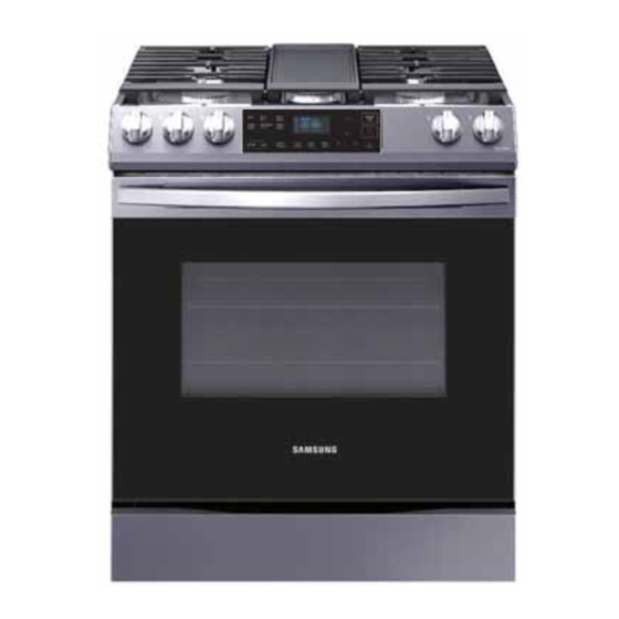
This document can not be used without Samsung’s authorization. Surface burners Oven vents Control panel Surface burner knobs (5 pcs) Removable oven door Storage drawer Broil oven burner Oven light Oven rack system Bake oven burner... -
Page 10: Control Panel - Oven
This document can not be used without Samsung’s authorization. 09 10 Oven modes Activates each oven modes (Bake or Broil). Keep Warm Keep Cooked food warm at lower temperayures between 150 F and 200 F (66 Bread Proof Activates the Bread Proof function. -
Page 11: Control Panel - Gas Cooktop
This document can not be used without Samsung’s authorization. LIGHTING A GAS SURFACE BURNER Make sure all surface burners are positioned and assembled properly. 1. Push in and turn the control knob to the LITE position. You will hear a “clicking”... - Page 12 This document can not be used without Samsung’s authorization. Model NX60T8111** Cavity Cavity Color Dark Blue Whole Oven(cu.ft) Upper Oven(cu.ft) Size Lower Oven(cu.ft) Drawer (cu.ft) Base Knob Feature Spray Knob Cooktop Frame CMF Black Porcelin Cooktop Illuminated Knobs Welcome Lighting (Ambient)
- Page 13 This document can not be used without Samsung’s authorization. Model NX60T8111** Oven - Cooking Mode 175°F (80°C) - 550°F (285°C) Bake Low - High Broil High Basic Function Convection Bake Convection Roast Keep Warm 175°F (80°C) Bread Proof 100°F (40°C)
- Page 14 This document can not be used without Samsung’s authorization. Model NX60T8111** Temp. Adjustment (+/-35F) Temp Unit (C/F) Conv. Auto Conversion (Default:-25F) 12 hour Energy Saving Sound On/Off Extra Features Wi-Fi On/Off Demo Mode Sabbath Time 12Hr/24Hr Manual Language Virtual Flame On/Off(Induction)
-
Page 15: Accessories
This document can not be used without Samsung’s authorization. Model NX60T8111** Accessories/Others Number of Rack Position Number of Racks Rack Gliding Rack Wire Rack(Flat) Broil rack Air Fry tray Divider(=Flex Duo) Meat Probe Griddle(AI/Cast Iron) Embedded Griddle Wok Grate Anti Tip Device... - Page 16 This document can not be used without Samsung’s authorization. Item Description Code No. Quantity Assy Grate Side Right DG94-03453A Assy Grate Center DG94-03441A Assy Grate Side Left DG94-03454A Broil Rack-Flat DG67-00225A Flat Rack DG75-01001D...
- Page 17 This document can not be used without Samsung’s authorization. 3. Disassembly and Reassembly 3. Disassembly and Reassembly Use for assembly and disassembly of all screws Use for assembly and disassembly of tubing to the cup Use for assembly and disassembly of injector nozzles.
-
Page 18: Step A) - Cover Back
This document can not be used without Samsung’s authorization. 3. Disassembly and Reassembly 3-1 (Step A) - Cover Back WARNING Disconnect power before servicing the range. Replace all panels before operating range. Failure to do so can result in death or electrical shock. -
Page 19: Step B) - Assy Control Box
This document can not be used without Samsung’s authorization. 3. Disassembly and Reassembly 3-2 (Step B) – Assy Control Box WARNING Disconnect power before servicing the range. Replace all panels before operating range. Failure to do so can result in death or electrical shock. -
Page 20: Step C) - Assy Frame Cooktop
This document can not be used without Samsung’s authorization. 3. Disassembly and Reassembly 3-3 (Step C) – Assy Frame Cooktop WARNING Disconnect power before servicing the range. Replace all panels before operating range. Failure to do so can result in death or electrical shock. -
Page 21: Step D) - Oven Door
This document can not be used without Samsung’s authorization. 3. Disassembly and Reassembly 3-4 (Step D) – Oven Door WARNING Disconnect power before servicing the range. Replace all panels before operating range. Failure to do so can result in death or electrical shock. - Page 22 This document can not be used without Samsung’s authorization. 3. Disassembly and Reassembly 3-5 (Step E) – Side Panel WARNING Disconnect power before servicing the range. Replace all panels before operating range. Failure to do so can result in death or electrical shock.
-
Page 23: Step E) - Side Panel
This document can not be used without Samsung’s authorization. 3. Disassembly and Reassembly Follow the Step A, B and C. Remove 6 screws from top side of Side Panel. Remove 6 screws from back side of Side Panel. Pull forward the Side Panel from the range. -
Page 24: Step F) - Assy Cooktop Burner
This document can not be used without Samsung’s authorization. 3. Disassembly and Reassembly 3-6 (Step F) – Assy Cooktop Burner WARNING Disconnect power before servicing the range. Replace all panels before operating range. Failure to do so can result in death or electrical shock. - Page 25 This document can not be used without Samsung’s authorization. 3. Disassembly and Reassembly Saddle Cable clamp 1. Follow the Step A, B and C. 2. Unpluged the cord or disconnect power Saddle 4. Release wire from Cable clamp and Saddle.
-
Page 26: Step G) - Assy Drawer
This document can not be used without Samsung’s authorization. 3. Disassembly and Reassembly 3-7 (Step G) – Assy Drawer WARNING Disconnect power before servicing the range. Replace all panels before operating range. Failure to do so can result in death or electrical shock. -
Page 27: Main Pcb Assembly
This document can not be used without Samsung’s authorization. 3. Disassembly and Reassembly 3-8 Main PCB Assembly WARNING Disconnect power before servicing the range. Replace all panels before operating range. Failure to do so can result in death or electrical shock. -
Page 28: Spark Module
This document can not be used without Samsung’s authorization. 3. Disassembly and Reassembly 3-9 Spark Module WARNING Disconnect power before servicing the range. Replace all panels before operating range. Failure to do so can result in death or electrical shock. -
Page 29: Pcb
This document can not be used without Samsung’s authorization. 3. Disassembly and Reassembly 3-10 PCB WARNING Disconnect power before servicing the range. Replace all panels before operating range. Failure to do so can result in death or electrical shock. WARNING EXPLOSION, FIRE, AND ASPHYXIATION HAZARD range. -
Page 30: Holder Pcb & Glass
This document can not be used without Samsung’s authorization. 3. Disassembly and Reassembly 3-11 HOLDER PCB & GLAS WARNING Disconnect power before servicing the range. Replace all panels before operating range. Failure to do so can result in death or electrical shock. -
Page 31: Electrode
This document can not be used without Samsung’s authorization. 3. Disassembly and Reassembly 3-12 Electrode WARNING Disconnect power before servicing the range. Replace all panels before operating range. Failure to do so can result in death or electrical shock. WARNING EXPLOSION, FIRE, AND ASPHYXIATION HAZARD range. -
Page 32: Burner Cup
This document can not be used without Samsung’s authorization. 3. Disassembly and Reassembly 3-13 Burner Cup WARNING Disconnect power before servicing the range. Replace all panels before operating range. Failure to do so can result in death or electrical shock. -
Page 33: Gas Orifice Nozzle (Single Burner)
This document can not be used without Samsung’s authorization. 3. Disassembly and Reassembly WARNING Disconnect power before servicing the range. Replace all panels before operating range. Failure to do so can result in death or electrical shock. WARNING EXPLOSION, FIRE, AND ASPHYXIATION HAZARD range. -
Page 34: Valve Cooktop
This document can not be used without Samsung’s authorization. 3. Disassembly and Reassembly 3-15 Valve Cooktop WARNING Disconnect power before servicing the range. Replace all panels before operating range. Failure to do so can result in death or electrical shock. - Page 35 This document can not be used without Samsung’s authorization. 3. Disassembly and Reassembly Follow the Step B and C,F. switch ignition and pull it straight out to release it from the control shaft. Using a tubing wrench and a channel lock wrench, disconnect the gas lines from the valve cooktop.
-
Page 36: Switch Ignition
This document can not be used without Samsung’s authorization. 3. Disassembly and Reassembly WARNING Disconnect power before servicing the range. Replace all panels before operating range. Failure to do so can result in death or electrical shock. WARNING EXPLOSION, FIRE, AND ASPHYXIATION HAZARD range. -
Page 37: Assy Motor
This document can not be used without Samsung’s authorization. 3. Disassembly and Reassembly 3-17 Assy Motor WARNING Disconnect power before servicing the range. Replace all panels before operating range. Failure to do so can result in death or electrical shock. - Page 38 This document can not be used without Samsung’s authorization. 3. Disassembly and Reassembly Follow the Step A and C. 2. Remove 3 screws from Cover back main and Cover adiabatic-top. Connector 3. Disconnect 1 terminal housing from the Assy Motor and Main Wire.
-
Page 39: Assy Door Latch
This document can not be used without Samsung’s authorization. 3. Disassembly and Reassembly 3-18 Assy Door Latch WARNING Disconnect power before servicing the range. Replace all panels before operating range. Failure to do so can result in death or electrical shock. -
Page 40: Switch-Door Plunger
This document can not be used without Samsung’s authorization. 3. Disassembly and Reassembly WARNING Disconnect power before servicing the range. Replace all panels before operating range. Failure to do so can result in death or electrical shock. WARNING EXPLOSION, FIRE, AND ASPHYXIATION HAZARD range. -
Page 41: Assy Lamp
This document can not be used without Samsung’s authorization. 3. Disassembly and Reassembly 3-20 Assy Lamp WARNING Disconnect power before servicing the range. Replace all panels before operating range. Failure to do so can result in death or electrical shock. -
Page 42: Temperature Sensor
This document can not be used without Samsung’s authorization. 3. Disassembly and Reassembly 3-21 SENSOR-THERMISTER WARNING Disconnect power before servicing the range. Replace all panels before operating range. Failure to do so can result in death or electrical shock. WARNING EXPLOSION, FIRE, AND ASPHYXIATION HAZARD range. -
Page 43: Gasket Door
This document can not be used without Samsung’s authorization. 3. Disassembly and Reassembly 3-22 Gasket Door WARNING Disconnect power before servicing the range. Replace all panels before operating range. Failure to do so can result in death or electrical shock. -
Page 44: 3-23Handle-Door, Glass Inner
This document can not be used without Samsung’s authorization. 3. Disassembly and Reassembly 3-23 Handle-Door, Glass Inner WARNING Disconnect power before servicing the range. Replace all panels before operating range. Failure to do so can result in death or electrical shock. - Page 45 This document can not be used without Samsung’s authorization. 3. Disassembly and Reassembly To remove Handle-Door Remove 2 screws to remove Handle- Door. To remove Glass-Inner (Up) Remove 6 screws to remove each Assy Hinge. Remove Glass Inner Sub. Disassemble Glass Inner Sub by unfolding...
- Page 46 This document can not be used without Samsung’s authorization. 3. Disassembly and Reassembly CAVITY SIDE GLASS: NO PRINT 5 Shorter Holes on this side (Away from coating side) Cavity side Check with multimeter: Coating Non coating side: no value GLASS INNER COATING DIRECTION:...
-
Page 47: Assy Power Cord
This document can not be used without Samsung’s authorization. 3. Disassembly and Reassembly 3-24 Assy Power Cord WARNING Disconnect power before servicing the range. Replace all panels before operating range. Failure to do so can result in death or electrical shock. -
Page 48: Burner Broil
This document can not be used without Samsung’s authorization. 3. Disassembly and Reassembly 3-25 Burner Broil WARNING Disconnect power before servicing the range. Replace all panels before operating range. Failure to do so can result in death or electrical shock. -
Page 49: Hot Surface Ignitor (Hsi) Of The Burner Broil, Nozzle Broil-Burner, Holder Broil-Burner
This document can not be used without Samsung’s authorization. 3. Disassembly and Reassembly Burner WARNING Disconnect power before servicing the range. Replace all panels before operating range. Failure to do so can result in death or electrical shock. WARNING EXPLOSION, FIRE, AND ASPHYXIATION HAZARD range. -
Page 50: Burner Bake
This document can not be used without Samsung’s authorization. 3. Disassembly and Reassembly 3-27 Burner Bake WARNING Disconnect power before servicing the range. Replace all panels before operating range. Failure to do so can result in death or electrical shock. -
Page 51: Hot Surface Ignitor (Hsi) Of The Burner Bake, Nozzle Bake-Burner, Holder Bake-Burner
This document can not be used without Samsung’s authorization. 3. Disassembly and Reassembly Burner WARNING Disconnect power before servicing the range. Replace all panels before operating range. Failure to do so can result in death or electrical shock. WARNING EXPLOSION, FIRE, AND ASPHYXIATION HAZARD range. -
Page 52: Assy Valve Safety
This document can not be used without Samsung’s authorization. 3. Disassembly and Reassembly 3-29 Assy Valve Safety WARNING Disconnect power before servicing the range. Replace all panels before operating range. Failure to do so can result in death or electrical shock. - Page 53 This document can not be used without Samsung’s authorization. 3. Disassembly and Reassembly Turn off the electrical supply going to the range. Shut off the gas shut-off valve in the gas supply line to the range. Carefully identify and mark the wires going to the ASSY VALVE SAFETY.
-
Page 54: Failure Display Codes
This document can not be used without Samsung’s authorization. 4. Troubleshooting 4. Troubleshooting 4-1 Failure Display Codes There are two kinds of error codes. One denotes an oven temperature sensor error and the other denotes a safety error. Possible error codes during use can be checked before service. - Page 55 This document can not be used without Samsung’s authorization. 4. Troubleshooting Hidden key list Numeric UI Range 8111 LED Range 8311 LED Range 8511 LED Function Time Key1 Key2 Key1 Key2 Key1 Key2 Child Lock 3sec Lock(3sec) Lock(3sec) Lock(3sec) Settings...
- Page 56 This document can not be used without Samsung’s authorization. 4. Troubleshooting Oven Sensor information Informaion code Meaning SOLUTION Disconnect power. Open the back cover. Disconnect sensor harness from control Measure sensor resistance Oven sensor opened (over C-20 whether there is a damaged terminal or wire harness.
- Page 57 This document can not be used without Samsung’s authorization. 4. Troubleshooting Oven Sensor information “C-20” [CN100] : Pin 11,13 < oven sensor > Disconnect power Measure sensor resistance. Replace the oven sensor. * reconnect Check the connecting condition of harness...
- Page 58 This document can not be used without Samsung’s authorization. 4. Troubleshooting Oven Sensor information Information code Meaning SOLUTION Disconnect power . Open the back cover. Disconnect sensor oven sensor. Check the broil, bake and convection heater . Check the resistance of the each heater.
- Page 59 This document can not be used without Samsung’s authorization. 4. Troubleshooting Oven Sensor information Broil Bake “C-21” DLB : TB200 – TB201 BROIL : TB202 – TB203 BAKE : TB204 – TB203 Disconnect power and Assy Display PCB DLB Relay Broil Relay Bake Relay Conv.
- Page 60 This document can not be used without Samsung’s authorization. 4. Troubleshooting Oven Sensor information Information code Meaning SOLUTION Disconnect power . Open the back cover .Check whether harness has been connected with door lock switch and motor. whether resistance value of door lock motor is normal.
- Page 61 This document can not be used without Samsung’s authorization. 4. Troubleshooting Oven Sensor information “C-d1” * Disconnect power. * Disconnect harness connected with Lock motor. * Lock motor switch check (com-NO) * Replace micro switch or Lock motor. * Measure resistance of Lock motor Coil.
- Page 62 This document can not be used without Samsung’s authorization. 4. Troubleshooting Oven Sensor information Information code Meaning SOLUTION Sub Touch communication C-F2 Replace sub PCB. information Replace Assy Touch. “C-F2” Replace Assy touch. Replace the sub PCB.
- Page 63 This document can not be used without Samsung’s authorization. 4. Troubleshooting Oven Sensor information Information code Meaning SOLUTION To reset error, disconnect power or press”OFF” key Ambient Temperature of C-A2 Operate the oven to Broil Mode to check cooling fan rotation display PCB very hot “C-A2”...
- Page 64 This document can not be used without Samsung’s authorization. 4. Troubleshooting Oven Sensor information Information code Meaning SOLUTION To reset error, disconnect power or press ‘Off’ key after opening the oven door at least 60sec Check whether oven vent or cover air is blocked by aluminum...
- Page 65 This document can not be used without Samsung’s authorization. 4. Troubleshooting Error Trouble Shooting SYMPTOM DIAGNOSIS REMEDY Check the circuit breaker or fuse for the range Measure the input voltage at the plug. circuit. (120VAC) Make sure all wires are connected to the PCB.
- Page 66 This document can not be used without Samsung’s authorization. 4. Troubleshooting Error Trouble Shooting SYMPTOM DIAGNOSIS REMEDY Make sure the harness connections at the PCB terminals (T02, T03) have not come loose or disconnected. Repair or replace the harness. ( Bake : TB205, BROIL : TB204,...
- Page 67 This document can not be used without Samsung’s authorization. 4. Troubleshooting Error Trouble Shooting REMEDY SYMPTOM DIAGNOSIS Make sure the door lock feature is Unlock the controls by pressing and holding the not turned on. lock key for 3 or more seconds.
- Page 68 This document can not be used without Samsung’s authorization. 4. Troubleshooting Error Trouble Shooting SYMPTOM DIAGNOSIS REMEDY Check the display control harness Reconnect securely or replace a damaged and connectors (CN430) on the PCB membrane control harness. The LED display is and membrane control panel.
- Page 69 This document can not be used without Samsung’s authorization. 4. Troubleshooting Error Trouble Shooting SYMPTOM DIAGNOSIS REMEDY Check for crimped gas line between the pressure gas regulator and the surface burner control Replace the damaged gas line. All surface burners manifold.
-
Page 70: Control Parts
This document can not be used without Samsung’s authorization. 4. Troubleshooting 4-2 Control parts No display No display. Make sure that power cord is Make sure that power cord is connected. Insert the power cord. connected Check the voltage of the Power cord Check the voltage of the Power Replace the Power cord. - Page 71 This document can not be used without Samsung’s authorization. 4. Troubleshooting Control parts Touch Keypad is not working properly Touch control keypads are not working properly. Make sure the Door lock feature is Touch the Start/Set keypad Touch the Start/Set keypad not turned on.
- Page 72 This document can not be used without Samsung’s authorization. 4. Troubleshooting Control parts Buzzer does not beep when keypad is touched. Buzzer does not beep when keypad is touched. Faulty buzzer on PCB. Replace the PCB.
-
Page 73: Cooktop Parts
This document can not be used without Samsung’s authorization. 4. Troubleshooting 4-3 Cooktop parts Cooktop burner not lighted [Gas malfunction] No cooktop burners will light. * Make sure the gas supply valve to * Fully open the gas supply valve. - Page 74 This document can not be used without Samsung’s authorization. 4. Troubleshooting Cooktop parts Cooktop burners not lighted [Electric malfunction] No cooktop Burners will light. *Plug in the power cord and/or * Make sure there is power to the reset the circuit breaker for the range.
- Page 75 This document can not be used without Samsung’s authorization. 4. Troubleshooting Cooktop parts One cooktop burner not lighted [Electric malfunction] One cooktop burner will not light. Check whether the burner head and Assemble the burner head and cap is properly assembled.
- Page 76 This document can not be used without Samsung’s authorization. 4. Troubleshooting Cooktop / Oven parts Gas Leaked Gas Leaked Check gas pipes on back side are properly Assemble the gas pipes on the right assembled. (10 points) position. Assemble the gas pipes on the right Check the Assy Valve Cooktop tube are position.
- Page 77 This document can not be used without Samsung’s authorization. 4. Troubleshooting Cooktop / Oven parts 1.82 1.04 1.38 0.83 1.40 0.83 1.92 1.12 1.00 0.62 Check whether the burner heads and Place the burner heads and caps properly. caps are properly assembled.
- Page 78 This document can not be used without Samsung’s authorization. 4. Troubleshooting Cooktop / Oven parts Flame size is too big or too small...
-
Page 79: Oven Parts
This document can not be used without Samsung’s authorization. 4. Troubleshooting 4-4 Oven parts Oven burner will not light [Broil / Bake burner] Oven burner will not light. Turn on the cooktop burners to check whether the gas is Open the gas valve. - Page 80 This document can not be used without Samsung’s authorization. 4. Troubleshooting Oven parts Oven temperature rises too slowly [Electric malfunction] Bake (120VAC) Broil (120VAC) Oven Temp rises to slowly. Turn on the cooktop burners to Open the gas valve. check whether the gas is properly supplied.
- Page 81 This document can not be used without Samsung’s authorization. 4. Troubleshooting Oven parts Oven temperature rises too fast. [Electric malfunction] Oven Temp rises to fast. * Repair or replace the harness. with in 10 minutes of room temperature operation. * Check the harness connections at PCB terminals (TB200~ TB206) and PCB * Faulty broil &...
- Page 82 This document can not be used without Samsung’s authorization. 4. Troubleshooting Oven parts Oven temperature rises too slow or too fast [Gas malfunction] Oven temperature rises too slow or too fast. * Make sure the gas supply valve to the * Fully open the gas supply valve.
- Page 83 This document can not be used without Samsung’s authorization. 4. Troubleshooting Oven parts Oven lamp not working Oven lamp is not working. * While holding the oven door open, * Make sure the control lockout feature press and hold the lockout keypad for is not turned on.
- Page 84 This document can not be used without Samsung’s authorization. 4. Troubleshooting Oven parts Wi-Fi Connection is not working Step.1 -Check whether Wi-Fi icon showed . Make sure that the mobile phone is connected to 2.4GHz Wi-Fi network. . Do not use the hidden AP in the wireless router settings during the device registration.
-
Page 85: Wiring Diagram
This document can not be used without Samsung’s authorization. 5. Wiring Diagram 5. Wiring Diagram 5-1 Wiring Diagram... -
Page 86: Main Pcb
This document can not be used without Samsung’s authorization. 5. Wiring Diagram 5-2 Main PCB... -
Page 87: Assy Display
This document can not be used without Samsung’s authorization. 5. Wiring Diagram 5-3 Assy Display... -
Page 88: Figure Of Pcb And Display
This document can not be used without Samsung’s authorization. 6. PCB Diagrams 6. PCB Diagrams 6-1 Figure of PCB and Display PCB MAIN ASSY DISPLAY... - Page 89 This document can not be used without Samsung’s authorization. 6. PCB Diagrams 1~2. BROIL HEATER 1~2. BAKE HEATER 3~4. BROIL/BAKE COMMON 3~4. LIVE COMMON 1~4. DLB IN 1~4. DLB OUT 1. EARTH 2. NC 3. NC 1. DOOR LOCK MOTOR 4.
- Page 90 This document can not be used without Samsung’s authorization. 6. PCB Diagrams HASS-MICOM-RX 1. +5V HASS-MICOM-TX 2. GND 3. DISPLAY-DIO HASS-BOOT 1. +5V 4. DISPLAY-CLK 2. GND 5. DISPLAY-STB1 3. TOUCH-RESET 6. DISPLAY-STB2 4. TOUCH-MOSI 7. DISPLAY-STB3 5. TOUCH-MISO 8. DISPLAY-STB4...
-
Page 91: Explanation Of Touch Keypad
This document can not be used without Samsung’s authorization. 6. PCB Diagrams 6-2 Explanation of Touch Keypad Touch control panel allows user to operate the oven, set clock & option, Wi-Fi on, turn on lamp by touching the control panel in the front. -
Page 92: Explanation Of Nx60T8111 Main Pcb Parts
This document can not be used without Samsung’s authorization. 6. PCB Diagrams 6-3 Explanation of NX60T8111 Main PCB parts Parts Part Name Funtion and Rule Number Circuit is designed to have broil relay or convection relay RY200 DLB Relay worked after DLB relay is being worked by Double line break. - Page 93 This document can not be used without Samsung’s authorization. 6. PCB Diagrams Parts Part Name Funtion and Rule Number RY207 Door Lock Relay This is relay which is connected with Door lock motor . RY208 Oven-Lamp Relay This is relay which is connected with Oven lamp.
-
Page 94: Explanation Of Nx60T8111 Display Pcb Parts
This document can not be used without Samsung’s authorization. 6. PCB Diagrams 6-4 Explanation of NX60T8111 Display PCB parts Parts Part Name Funtion and Rule Number Main-Sub Communication CN100 This is connector to communicate main with display. connector This is connector for HASS (Home appliance smart service). - Page 95 North & Latin America gspn3.samsungcsportal.com China china.samsungportal.com This service manual is the property of Samsung Electronics Co., Ltd. © Samsung Electronics Co., Ltd. May, 2020 Any unauthorized use of this manual can be punished under applicable Printed in Korea international and/or domestic law.