
Related Manuals for Pentax R-200 Series


Summary of Contents for Pentax R-200 Series
- Page 1 R-200 Series E f f i c i e n t a c c u r a c y a t y o u r f i n g e r s ! • 350m reflectorless EDM range • 2” and 5” models •...
- Page 2 The measurement range of reflectorless is determined by the white side of the Kodak Gray Card. (KODAK is a trademark of Eastman Kodak Company) *2 Reflector sheet: PENTAX genuine Reflector sheet *3 The measurement range may vary by conditions of the environment.
- Page 3 InstructIon manual Basic Procedures for r-200 serIes r-202ne r-205ne (Power) TI Asahi Co., Ltd. International sales Department 4-3-4 ueno Iwatsuki-Ku, saitama-shi saitama, 339-0073 Japan tel.: +81-48-793-0118 fax. +81-48-793-0128 e-mail: International@tiasahi.com www.pentaxsurveying.com/en/...
-
Page 4: Table Of Contents
CONTENTS GENERAL Contents Exemption clause Copyright Precautions regarding safety Warning Usage Precautions 1. BASIC OPERATION 1.1 Names of parts 1.2 Unpacking and packing 1.3 Standard equipment 1.4 Removing and attaching the Battery 2. DISPLAY AND KEYBOARD 2.1 Display and keyboard 2.2 Operation keys 2.3 Function keys 2.4 Alphanumeric input... - Page 5 6.2 Distance measurement 6.3 Quick mode 7. CORRECTION MODE 7.1 Changing the target constant 7.2 Changing the temperature 7.3 Changing the atmospheric pressure 7.4 Changing the ppm value 8. INITIAL SETTING 8.1 Overview 8.2 Entering the mode for initial setting 1 8.3 Entering the mode for initial setting 2 8.4 Entering the mode for initial setting 4 8.5 Entering the mode for initial setting 5...
- Page 6 13.6 Distance range 14. Notice to the user of this product...
-
Page 7: Exemption Clause
Before using this product, be sure that you have thoroughly read and understood this instruction manual to ensure proper operation. After reading this manual, be sure to keep in a convenient place for easy reference. Exemption clause 1) TI Asahi Co.,Ltd. (TIA) shall not be liable for damage caused by Acts of God, fire, alteration or servicing by unauthorized parties, accident, negligence, misuse, abnormal operating conditions. -
Page 8: Precautions Regarding Safety
PRECAUTIONS REGARDING SAFETYxx Safety precautions (Must be followed) The following items are intended to prevent possible injury to the user or other people and/or damage to the instrument before it occurs. These safety precautions are important to the safe operation of this product and should be observed at all times. Distinctive displays The following displays are used to distinguish precautions by the degree of injury or damage that may result if the precaution is ignored. - Page 9 areas. If this instrument is used close to industrial areas or transmitters, the equipment can be influenced by electromagnetic fields. • Do not use this product in a coal mine, in a location where there is coal dust, or near flammable material as there is a risk of explosion.
- Page 10 • Make sure the tripod itself and the instrument on the tripod are both installed securely as insecure installation may cause the tripod to fall over or the instrument to drop, resulting in possible injury. • Do not carry the tripod with the metal shoe pointing toward another person as it may injure him/her.
-
Page 11: Usage Precautions
Do not stare into the laser beam. R-200 is a Class IIIa (3R) Laser product. [EDM axis] The R-200 series EDM is a red visible laser beam and the beam diameter is very small. The beam is emitted from the objective centre. The EDM axis is designed to coincide with the telescope sight axis (but both axes may deviate slightly because of intense temperature changes and a long time lapse). - Page 12 [Battery & charger] • Do not use any battery or battery charger that is not approved by Pentax as it entails a risk of damaging the instrument. • If water should happen to splash on the instrument or the battery, wipe it off immediately and allow it to dry in a dry location.
- Page 13 [Checks and repairs] • Always check the instrument before beginning work and check that the instrument is maintaining the proper level of precision. Pentax bears absolutely no responsibility for damages due to survey results obtained from surveys conducted without an initial instrument check.
-
Page 14: Basic Operation
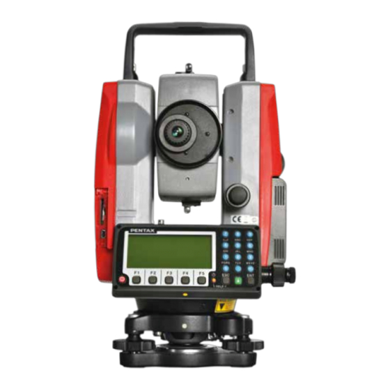
1. BASIC OPERATION 1.1 Names of parts Focus ring Collimator Laser indicator Instrument height mark Eyepiece Battery latch Plate vial Battery pack Telescope tangent screw Telescope clamp screw Display panel Key board Clamp screw Plate vial Tangent screw Detaching knob Leveling screw Base plate Top handle... -
Page 15: Unpacking And Packing
1.2 Unpacking and packing [Unpacking the Instrument from the case] ① Set the case down gently with the lid facing upwards. ② Open the latches while pressing down on the lock (safety mechanism) and open the lid of the case. ③... - Page 16 ① Place the channel on the bottom of the battery pack. ② Onto the protrusion of the instrument and push the battery pack down into place. ③ Turn the knob clockwise. Remaining Battery Charge When the instrument’s power is turned on, a battery mark “ ”will be displayed on the right of the display screen.
- Page 17 ① Draw the battery to the lock lever side and put it on the battery pocket. The battery is firmly installed on the battery pocket. ② Press down the battery and then slide it to the opposite direction of the lock lever. ③...
- Page 18 ② Leave just as it is until the charge is completed. ③ When the charge is completed, the charge lamp is turned off. ④ Detach the battery packing from the charger when the charge is completed. [Refreshing the battery] The use time shortens gradually by the phenomenon of “Effect of the memory” when the NiMH battery leaves capacity and repeats the charge.
-
Page 19: Display And Keyboard
2. DISPLAY AND KEYBOARD 2.1 Display and keyboard Alphanumeric and +/- key Enter key Laser key Power supply key Function key Illumination key ESC key 2.2 Operation keys Description ON/OFF of power supply. [POWER] Returns to previous screen or cancels an operation. [ESC] Turns the illumination of the LCD display and telescope reticle on [ILLU]... - Page 20 Switches the target. [TARGET] REFLECTORLESS / SHEET / PRISM Resets the horizontal angle to 0° 0’ 0” by pressing twice. [0 SET] Switches the display composition in the order [DISP] “H.angle/H.dst./V.dst.”, “H.angle/V.angle/S.dst.” and “H.angle/V.angle/H.dst./S.dst./V.dst.”. Switches the screen between MODE A and MODE B. [MODE] MODE B PowerTopoLite Special Functions.
-
Page 21: Alphanumeric Input
Press the numeric key 0 and 2 to move to Menu 2 or press [F4] [ ▽ ]. 2.4 Alphanumeric input The point name is input by the alphanumeric keys as following. Letter under key Letter & figure order to input [@][.][_][-][:][/][0] PQRS [P][Q][R][S][p][q][r][s][1]... -
Page 22: Preparation For Surveying
3. PREPARATION FOR SURVEYING 3.1 Centring and Levelling of the Instrument [Setting up the instrument and the tripod] ① Adjust the tripod legs so that a height suitable for observation is obtained when the instrument is set on the tripod. ②... -
Page 23: Optical Plummet (Option)
Sometimes the state of the surface of the ground mark or a surrounding environmental does not allow observing the laser spot easily. Please adjust the brightness of the laser if necessary. If [Laser] + [F4] [PLUM.ADJ] are pressed in due course., the brightness adjustment screen of the laser plummet device, is displayed. -
Page 24: Levelling With Circular Vial
[Shift type] ①Look through the optical plummet eyepiece, and rotate the eyepiece knob until the center mark can be seen clearly. ②Rotate the focusing knob of the optical plummet and adjust the focus on the ground mark. ③Loosen the centering clamp screw and push the upper plate by finger and stay the center mark on the ground mark. -
Page 25: Eyepiece Adjustment
⑥Confirm whether the plummet is on the ground mark. When you confirm it is not on the mark, loosen the center screw and move the instrument over the ground mark correctly and fix the instrument by a center screw. Repeat from ①to⑥. 3.6 Eyepiece adjustment [Eyepiece adjustment] The eyepiece adjustment is performed before target... -
Page 26: Attachment And Detachment Of Tribrach
• The Focus ring rotation “clockwise” makes it possible to focus on closer objects and “counter clockwise” will focus on further objects. 3.8 Attachment and detachment of tribrach The tribrach of R-202NEand R-205NE can be detached from the instrument, if required when replacing the instrument with a prism for example. -
Page 27: Turning The Power On
4. TURNING THE POWER ON 4.1 Turning the Power On and Off Pressing the [POWER] key shows the initialscreen.(The [POWER] key is also used to turn the power off.)After a few seconds, it turns to Electronic vial screen. Move the vials to center by adjusting the leveling screws.Pressing the [ENT] key views the angle and distance measurement screen. -
Page 28: Adjusting Illumination Brightness
• LCD contrast may be unappealing under certain environmental conditions such as high temperature. Adjust the LCD contrast as described above in such situations. 4.3 Adjusting illumination brightness Press [F5] while holding down the Illumination key to access the screen for adjusting illumination brightness. -
Page 29: Angle Measurement
5. ANGLE MEASUREMENT 5.1 Measuring an angle Aim at the first target, then press [F3] [0 SET] twice in succession to reset the horizontal angle to 0. Aim at the second target, then read the horizontal angle. Pressing [F4] [DISP] displays the vertical angle. •... -
Page 30: Inputting An Arbitrary Horizontal Angle
• lf you want to hold the horizontal angle when you are in MODE A, press [F5] [MODE] first to switch to MODE B, then press [F3] [HOLD]. • The [F3] [HOLD] cannot hold the vertical angle or distance. • To release the horizontal angle from being held, press [F3] [HOLD] once. •... -
Page 31: Displaying The Slope % Of The Vertical Angle
Press the [ENT] key to accept the horizontal angle set to 123° 45' 20" and change the screen to MODE A. • The former data is called by pressing the [CLEAR] key again. 5.5 Displaying the slope % of the vertical angle Press [F5] [MODE] to enter MODE B. - Page 32 Press [F5] [MODE] to enter MODE B. Press [F2] [ANG SET] to display the ANGLE SET screen. Press [F4] [ ] to move the cursor to “3. R/L REVERSE”. Press [F5] [SELECT] to add a minus sign (-) to the horizontal angle value as a counter clockwise angle.
-
Page 33: Distance Measurement
6. DISTANCE MEASUREMENT 6.1 Target setting The target mode and its Constant of current setting are shown at the left of the battery mark. For example in case of each Constant 0, Reflectorless (Non-Prism); N 0, Prism; P 0 Pressing [F2] [TARGET] changes the target mode. •... -
Page 34: Distance Measurement
6.2 Distance measurement The R-200 series has two distance measurement modes of primary MEAS and second MEAS. Pressing the [F1] [MEAS] one time goes to primary MEAS and twice goes to second MEAS. -
Page 35: Quick Mode
• If the instrument is in MODE B, press [F5] [MODE] to switch to MODE A and press [F1] [MEAS ] twice. • Pressing [F1] [MEAS] twice after collimating the telescope at the Target starts Continuous distance measurement at fast speed with the “MEAS” text blinking. It remains blinking during the measurement. -
Page 36: Correction Mode
7. CORRECTION MODE 7.1 Changing the target constant Changing the Target Constant can be performed only when the Reflector sheet and Prism Constant setting are “INPUT” in initial setting 1. Example: Prism Constant -25mm setting Press [F4] [CORR] in MODE B. (If the instrument is in MODE A, press [F5] [MODE] to enter MODE B.) Press the [F5] [SELECT] to enable... -
Page 37: Changing The Temperature
• Once set, the Reflector sheet Constant and Prism Constant remain on the measurement screen as “S 0” or “P 0”. • The factory initial of Reflector sheet Constant and Prism Constant are 0. • Once set, each Constant remains in memory even after the power is turned off. 7.2 Changing the temperature The temperature setting can be changed only when “ATM CORR”... -
Page 38: Changing The Atmospheric Pressure
• The factory initial of temperature is “+15°C”. • Once set, the temperature remains in memory even after the power is turned off. • Temperature correction is based on 15°C. If this instrument is used without correcting the temperature, a distance error per 100m is about -0.1mm per +1°C as a temperature difference from 15°C. -
Page 39: Changing The Ppm Value
When “*” is on the screen, the pressure cannot be changed. If “ATM CORR” in “initial setting 1” has been set to “2.ppm INPUT”, no pressure is displayed on the correction menu screen. • Once set, the pressure is displayed at the centre of the top of the measurement screen. •... - Page 40 • The valid range of ppm values is from -199 to +199. • Once set, the ppm value is displayed at the centre of the top of the measurement screen. • The factory initial of ppm value is “0”. • Once set, the ppm value remains in memory even after the power is turned off.
-
Page 41: Initial Setting
8. INITIAL SETTING 8.1 Overview For the R-200 series, you can select and save the desired setting for a variety of prescribed instrument conditions, called initial setting. The Initial Setting is saved in four modes, “initial setting 1”, “initial setting 2”,, “initial setting 4”, and “initial setting 5”... -
Page 42: Example Of Changing An Initial Setting Content (Selection Of Atmospheric Correction)
• Select the item of interest in the same way as in the mode for initial setting 5. 8.6 Example of changing an initial setting content (selection of atmospheric correction) This section describes the operating procedures for selecting “1.ATM CORR” in initial setting 1 as an example of changing an initial setting content. -
Page 43: Initial Setting
8.7 Initial setting 1 Selection of Atmospheric Correction: X1.ATM INPUTaXXX By entering ppm value, or by fixing the ppm value to 0 2.ppm INPUT (NIL) not to perform Atmospheric Correction. 3.NIL 1. Selection of Prism Constant: [PRISM CONST.] X1.-30mmXaXXXXXX Select whether the Prism Constant to be input is set to 2. -
Page 44: Initial Setting
3. Selection of the quick measuring:ON/OFF X1.OFF XaXXXXXX 2.ON 4. Selection of Long range message X1.OFF XaXXXXXX : [LONG RANGE MES.] 2.ON 5. Selection of Laser plummet : [LD PLUM.] X1.OFF XaXXXXXX Laser plumb ON/OFF is selected. 2.ON 6. Selection of Minimum angle display: [MIN UNIT ANG.] 1.COARSE Select whether to set the minimum angle display mode to X2.FINEXXXXXXXXX... -
Page 45: Initial Setting
3. Selection of Distance unit setting: [DIST. UNIT] X1.m XXXXX Select m or ft or ft+inch as the unit for Distance. 2.ft 3.ft+inch X1.DEG 4. Selection of Angle unit setting: [ANG. UNIT] Select DEG or DEC or GRD or MIL as the unit for Angle. 2.DEC 3.GRD 4.MIL... -
Page 46: Accessing The Functions
9. ACCESSING THE FUNCTIONS 9.1 Accessing by help key You can use the [HELP] key to display specific 、 、 2、401TARGET CONST:-30mm initial setting (such as the prism constant and 3、402ATM CORR :ATM INPUT atm corr). 4、502SHOT COUNT 5、503CRV/REF CORR:0.14 Press the [ILLU]+[ESC] key in MODE A or B. -
Page 47: Instrument Setting Items
[Instrument setting items] HELP menu list Default Other options TARGET CONST PRISM CONST -30mm 0mm, INPUT SHEET CONST INPUT ATM CORR ATM INPUT ppm INPUT, NIL SHOT COUNT SHOT COUNT 1TIME 3TIMES, 5TIMES, INPUT SHOT INPUT 01TIMES (input) CRV/REF CORR. 0.14 0.2, NIL MIN UNIT ANG. -
Page 48: Checks And Adjustments
10. CHECKS AND ADJUSTMENTS • Checks and adjustments should be performed before and during measurement. • The instrument should be checked after long storage and transportation. • The checks should be performed in the following order. [Cautions on CHECKS AND ADJUSTMENTS] •... -
Page 49: Vertical Reticle
Adjustments When the bubble of the Circular vial comes off from the center according to check procedure ②, it is necessary to adjust. Turn the bubble adjustment screw with a hex wrench (L type wrench) and put the bubble in the center of the circle. -
Page 50: Perpendicularity Of Line Of Sight To Horizontal Axis
Reticle adjusting screws 10.4 Perpendicularity of line of sight to horizontal axis Checks ①Position a target Point A at a distance 30m - 50m away from the instrument, and sight it with the telescope. ②Loosen the telescope lock screw and turn the telescope until a point is sighted at a distance roughly equal to that of Point A. -
Page 51: Vertical 0 Point Error
When a center part where a cross intersection and the laser mark look the brightest shifts by 0.8mm or more (at the instrument height 1.5m), it is necessary to adjust it. A repair engineer does this adjustment. Please contact the PENTAX dealer. -
Page 52: Optical Plummet
10.7 Optical Plummet Checks ①Set the instrument on the tripod, and place a piece of white paper with a cross drawn on it right under the instrument. ②Look through the optical plummet, and move the paper so that the intersecting point of the cross comes to the center of the field of view. -
Page 53: Beam Axis And Line Of Sight
The check of the offset constant can be done on a certified base line. It can also be obtained in a simple way as described below. Checks 1. Locate points A, B and C at about 50m intervals on even ground. 2. -
Page 54: The Edm Beam Axis
●If instrument function is not as described in ④, contact your local dealer. ●This check should be done under good weather conditions. 10.10 The EDM beam axis The distance measurement (EDM) beam axis is adjusted to be aligned to the sighting axis of the telescope, but it can be changed a little in case of rapid temperature change, shock or aging. - Page 55 Adjustments At the procedure 4. above, if the “Center” of laser spot is not within the internal circle (10mm) of the target plate, the adjustment is necessary. Please contact your PENTAX dealer.
-
Page 56: Specifications
11. SPECIFICATIONS R-202NE R-205NE Telescope Image Erect Optical aperture 45mm EDM aperture 45mm Reticle Intensity settings: 10 steps illumination Pointer Visible la ser Magnification 30 x Resolving power 3” Field of view 2.6% (1° 30’) Minimum focus 1.0m Focus Manual Distance measurement Laser Class Visible Laser: Class II (2) / Class IIIa (3R) -Long range mode in Reflectorless... - Page 57 Battery pack BP02C Power source Ni-MH (Rechargeable)(4300mAh) Operation time Continuous Approx. 5 hrs (ETH+EDM),12 hrs (ETH) with Approx. 2.2 hrs of charging time Weight Approx. 380g Weight 280g Internal Memory Coordinates 20000 points data Note: The measurement range and accuracy of Reflectorless are determined by the white side of the Kodak Gray Card.
-
Page 58: Data Collector
12. DATA COLLECTOR The instrument can communicate directly with a computer through the RS232C interface. By use of a data collector you can automate data entry from the collection of survey data to the transfer of the data to a computer. This is useful in saving time and protecting data integrity. ●About connection with data collector and the handling, please refer to an “Instruction manual”... -
Page 59: Appendix
The speed at which light travels through the air varies depending on the temperature and atmospheric pressure. The R-200 series is designed to measure distances at the speed of light in order to measure accurately, Atmospheric Correction needs to be used. The instrument is... -
Page 60: Hpa And Mmhg Conversion Table
designed to correct for weather conditions automatically if the temperature and pressure are input. Correction is then carried out based on the following formula. K: Atmospheric Correction Constant P: Atmospheric pressure (hPa) t: Temperature(°C) Distance after Atmospheric Correction D = Ds (1+K) Ds: Measured distance when no Atmospheric Correction is used. -
Page 61: Atmospheric Refraction And Earth Curvature Correction
Error table: When hPa (15°C, 1013hPa as standard) Unit:mm 1200 1100 1013 C° -0.5 -2.6 -5.5 -8.0 -10.5 -13.0 -15.5 -1.8 -4.7 -7.3 -9.9 -12.5 -15.1 -0.9 -4.0 -6.6 -9.3 -12.0 -14.6 -0.0 -3.1 -5.9 -8.6 -11.4 -14.2 -2.2 -5.1 -8.0 -10.8 -13.7... - Page 62 ●Calculation formula when atmospheric refraction and earth curvature correction parameter is set to “OFF”: S: Slope distance α: Vertical angle from horizontal K: Atmospheric refraction coefficient (0.14 or 0.2) Re: Diameter of earth (6,370 km) 13.6 Distance Range Generally speaking, the maximum range which can be measured varies considerably depending on the atmospheric conditions.
- Page 63 C) Maintenance and repair not covered in this manual must be done by an authorized Pentax dealer. D) The Laser beam emission by the Distance measurement can be terminated by pressing F1 MEAS key.
- Page 64 TI Asahi Co., Ltd. International Sales Department 4-3-4 Ueno Iwatsuki-Ku, Saitama-Shi Saitama, 339-0073 Japan Tel.: +81-48-793-0118 Fax. +81-48-793-0128 E-mail: International@tiasahi.com www.pentaxsurveying.com/en/ Japan Surveying Instruments Manufacturers’ Association Member symbol of the Japan Surveying Instruments Manufacturers’ Association representing the high quality surveying products. Copyright ©...
- Page 65 InstructIon manual PowertoPolite for r-200 serIes r-202ne r-205ne (Power) TI Asahi Co., Ltd. International sales Department 4-3-4 ueno Iwatsuki-Ku, saitama-shi saitama, 339-0073 Japan tel.: +81-48-793-0118 fax. +81-48-793-0128 e-mail: International@tiasahi.com www.pentaxsurveying.com/en/...
- Page 66 Copyright Copyright © 2012 TI Asahi.Co.Ltd All Rights Reserved TI Asahi.Co.Ltd. is a sole proprietor of the PowerTopoLite software.The PowerTopoLite software and publication or parts thereof, may not be reproduced in any form, by any method, for any purpose. TI Asahi.Co.Ltd. makes no warranty, expressed or implied, including but not limited to any implied warranties or merchantability or fitness for a particular purpose, regarding these materials and makes such materials available.
- Page 67 Display and Keyboard Basic display and keyboard of R-200 series are described below, and the function keys of PowerTopoLite are described at “2. ACCESSING THE POWERTOPOLITE”. Alphanumeric and +/- key Enter key Laser key Power supply key Function key Illumination key ESC key Operation Key Description...
- Page 68 Function key Display F. Key Description Mode A [MEAS] Pressing this key one time measures the distance in normal mode(another measurement type can be selected by Initial Setting 2.) [MEAS] Pressing this key twice measures the distance in coarse mode(another measurement type can be selected by Initial Setting 2.) [TARGET] Select the target type by following order.
- Page 69 Alphanumetric Input The point name etc. is input by the alphanumeric keys as following. Letter under Key Letter & Figure order to input [@][.][_][-][:][/][0] PQRS [P][Q][R][S][p][q][r][s][1] [T][U][V][t][u][v][2] WXYZ [W][X][Y][Z][w][x][y][z][3] [G][H][I][g][h][i][4] [J][K][L][j][k][l][5] [M][N][O][m][n][o][6] [ ][?][!][_][ ][^][|][&][7] [A][B][C][a][b][c][8] [D][E][F][d][e][f][9] [.][,][:][;][#][(][)] [+/-] [+][-][ * ][/][%][=][<][>]...
- Page 70 CONTENTS Copyright Display and Keyboard Memories in the Instrument Relations between memories and each function (TOP COVER) .............................. CONTENTS ......................................5 1. INTRODUCTION ..............................7 1.1 I ................................ 7 NTRODUCTION 1.2 B ....................... 7 EFORE USING THE OWER ITE MANUAL 2.
- Page 71 8. CALCULATIONS ..............................42 8.1 COGO................................... 42 8.1.1 INVERSE............................... 42 8.1.2 POINTS COORDINATES ..........................45 8.1.4 LINE-ARC INTERSECTION......................... 51 8.1.5 LINE-LINE INTERSECTION........................53 8.1.6 ARC-ARC INTERSECTION.......................... 55 8.1.8 POINT DISTANCE OFFSET ........................59 8.1.9 ARC DISTANCE OFFSET ..........................61 8.2 2D SURFACE............................... 63 8.3 3D SURFACE AND VOLUME..........................
-
Page 72: Introduction
Thank you for your first looks at PowerTopoLite by reading this manual. The PowerTopoLite is a user friendly data collection and calculation program for the PENTAX total station R-200 series. PowerTopoLite is developed based on PowerTopo, which is known as versatile on-board software for PENTAX ATS total station series. - Page 73 “PowerTopoLite” or “Structure type” that took over functionality of our past product in ”Action Method Selection”. The R-200 series instrument has a Job name of “PENTAX” as its default setting. And, therefore, each data is stored in the “PENTAX” unless another new Job name is created. When another Job name is created, each data is stored in the new Job name.
-
Page 74: Accessing Powertopolite
2. ACCESSING POWERTOPOLITE 2.1 How to access PowerTopoLite To access the R-200 Special Functions of the PowerTopoLite, perform the following procedures. a. Press the Power (ON/OFF) key to view the R-200 start-up screen. b. Press the [F5][MODE] to view Mode B screen. c. -
Page 75: Typical Function Keys Of Powertopolite
CALC Calculation Virtual Plane Measurement Remote Distance Measurement Other four Functions are viewed by pressing [F5][PAGE]. Function key Description TRAV Stake out ROAD ROAD DESIGN Input and Output PREF Preference b. INVERSE, POINT COORDINATES, LINE-LINE INTERSECTION functions CALCULATION screen is viewed by pressing [F2][CALC]. The CALCULATION consists of COGO, 2D SURFACE and 3D SURFACE &... - Page 76 Allow you to add more points for the free stationing. CALC Starts the calculation of the free stationing. NEXT Views the next known point Coordinates setup screen. DATA Views the TARGET POINT screen. TARGET Selects the Target type Selects the EDM settings Selects all points of current job ORDER The order of selected points...
-
Page 77: File Manager
3.1 Information of the remaining memory available Press [ENT] to view INFORMATION screen. The remaining memory available and a JOB name PENTAX are viewed on the screen. The Job name “PENTAX” is a default setting. 3.2 Creation of a new Job Select 2. -
Page 78: Selection Of A Job
Press [ENT] to view JOB SELECTION screen. 3.3.1 Selection of a Job Select 1. JOB LIST SEARCH and press [ENT] to view its screen. JOB LIST is a list of all stored Jobs. Select your desired Job name and press [ENT] to select. 3.3.2 Selection by a Job name input Select 2. -
Page 79: Deletion From A Job List
JOB CONFIRMATION screen. Press [ENT] to delete or [ESC] to abort. The R-200 series instrument has a Job name of the “PENTAX” as its default setting. Therefore, each data is stored in “PENTAX” unless another new Job name is... -
Page 80: All Clear
3.5 All Clear Select 5. All Clear by pressing the down arrow key. Press [ENT] to view its screen. Warning: When [CLEAR] is pushed, all Job Files are deleted. NOTE: - Creating several new JOB Files and writing-in or rewriting data on the same JOB Files repeatedly may cause the time of writing-in and rewriting of the data to be slower. -
Page 81: Measure
4. MEASURE Offset 3.Rotated Reference 1.Cylinder Remote 2.Fixed plane Backsight P. Coordinates Azimuth Station Point An operator can measure the Foresight point Coordinates from the “Station point Coordinates and Backsight Coordinates” or the “Station point Coordinates and Azimuth”, and can store the Point name and measured Coordinates in the memory. -
Page 82: Point Name, Pn, Input
Select 1. RECTANGULAR COORD. and press [ENT] to view the STATION POINT SETUP screen. mark is used to scroll up / down. 6. PC is viewed by scrolling down. 4.1.1 Point name, PN, input Press [ENT] to view the PN screen. The [ENT] is used for both accepting the selected choice and opening the input screen of the Coordinates values etc.. - Page 83 IH value: Press [ENT] to view the IH, Instrument height, screen. Input your desired IH value by pressing each keys. PC, Point Code: Press [ENT] to view and input the PC, Point code, screen. If PointCode exists, you can easily select them from the list.
-
Page 84: Station Orientation
[ENT] to view POINT SELECTION FROM the LIST screen. Press [ENT] to view STATION POINT SETUP screen. 4.2 Station Orientation Press the [F1][ACCEPT] to view the STATION POINT H. ANGLE SETUP screen. Please, note that the rotation of the “H.angle” depend on the rotation setting of “Coordinate axis definition”. -
Page 85: Measuring
Press the [MEAS] to measure the Distance and display the Coordinates. 1) Press [F5][PAGE] twice to view [F3][ANG & DIST]. 2) Press [F3][ANG & DIST] to view [F3][COORD.] and Angle and Distance values. 3) Press [F3][COORD.] to view [F3][ANG&DIST] and Coordinates. 4.3 Measuring Aim at the reference point and press [ENT] to view the MEASURE screen. - Page 86 Contents of “PointCodeList.csv”: 1,,PointCodeList, 31,,1,ABC,,,, 31,,2,DEF,,,, 31,,3,GHI,,,, 31,,4,JKL,,,, 31,,5,MNO,,,, 31,,6,PQR,,,, 31,,7,STU,,,, 31,,8,VW,,,, 31,,9,XYZ,,,, Format of the “PointCodeList” file Field 1 Field 2 Field 3 Field 4 Field 5 Field 6 Field 7 Description Record Type Name Description Ex. Line 1 PointCodeList, Job record Job No.:...
-
Page 87: Remote, Offset, Station, And H. Angle Function
4.5 Remote, Offset, Station, and H. angle function 4.5.1 Remote Press [F5][PAGE] to view another MEASURE menu. Press [F1][REMOTE] once and then quickly press this key again to measure your desired point Coordinates by moving the telescope. The displayed Coordinates automatically change according to your aiming point. The Remote is a function of, so to speak, “Real-time offset”. -
Page 88: Offset
Three type menus can be used by pressing [F5][PAGE]. Another is following menu. The target type can be selected by pressing [F2][TARGET]. POT3 X.XXX m EDM settings can be selected by pressing [F1][EDM]. For example, change 1.PRIM. MEAS KEY (MEAS) to TRACK SHOT or TRACK CONT if you want to use tracking measurement with primary MEAS key (MEAS). -
Page 89: Station
Offset P VO: Vertical Offset ( Along the third axis ) Offset P DO: Distance Offset ( Along the line of measurement, thus along the slope ) Offset P TO: Tangential offset ( TO: On the horizontal plane, perpendicular to the horizontal line between Station and Point. -
Page 90: Station Setup [ By Polar Coordinates]
4.6 Station setup [ By Polar Coordinates] The same Point Name of the plural polar points can be saved. Press [F2][MEAS] of the PowerTopoLite screen to view the MEASURE METHOD SELECTION screen. Select 2. POLAR COORD. and press [ENT] to view the STATION POINT SETUP screen. -
Page 91: Station Orientation
Input the TEMP value. Press [ENT]. Input the PRESS value. Press [ENT]. Input ppm value. Press [ENT]. TEMP, PRESS and ppm input depend on the “Initial setting 1” (ATM INPUT, ppm INPUT, NIL). 4.7 Station Orientation Press the [F5 ][ ACCEPT] to view the STATION POINT H. ANGLE SETUP screen. Input your desired H.angle. -
Page 92: Measuring
Press [ENT] after aiming back sight point. Aim at the reference point and press [ENT] to view the MEASURE screen. 4.8 Measuring Then, aim at the Target point and press the [F1][MEAS] to measure the distance. Press [F3][ME/SAVE] to measure and save the measured data. Press [F2][SAVE] to save the measured data. - Page 93 Offset P: Offset Point Offset P DO: Distance Offset ( Along the line of measurement, thus along the slope ) Offset P Press the [F4][OFFSET] to view the OFFSET screen. Offset enables you to work with Offset. The following offset are available. Press [ENT] to view the offset input window.
-
Page 94: View And Edit
5. VIEW AND EDIT Stored data are displayed graphically, and the edit of the stored data is possible by this Function. The Z Coordinate (the height) of the point is ignored in the graphical display of the point data. Four menu items are available: GRAPHICAL VIEW CREATE THE RECT. -
Page 95: Edit The Data
Select 2. CREATE THE RECT. POINT and press [ENT] to view the RECT. DATA EDIT screen. Input the PN, X, Y, Z and PC. Press [ENT] to save them. Press [F2][LIST] to view the saved points. The first line of the screen shows now displayed point and the total number of points. Press [F1][DELETE] to delete your desired point. - Page 96 Your desired points are deleted and found as described above. After selecting desired point with arrow key, press [ENT] to view the RECT. DATA EDIT screen to edit. 1.PN :XXXX 2.IH :XXXX.XXX m 3.TEMP :+ 000000XX.000 m 4.PRESS :+ 000000XX.000 m 5.ppm :+ 000000XX.000 m You can edit data and save it.
-
Page 97: Free Stationing
6. FREE STATIONING Point 2 Coordinates Point 3 Coordinates Point 1 Coordinates Coordinates Point 4 Coordinates The Station point Coordinates is calculated from the plural known points. To gain the Coordinates, at least two H. angles and one distance or three H. angles are required. If not so, the error message of “Not enough data to Calculate! 2 angles and 1 distance, 3 angles are required”... - Page 98 Press [ENT] to view the ADD/CALC. SELECTION MENU screen. (Measuring is not needed. Just press [ENT].) Press the [F1][ADD] to view the KNOWN POINT COORD. SETUP screen. Aim at Point 2, 3 and 4. In the same manner, input the values of Point 2,3 and 4. After entering values of PN4, press [ENT] twice to view the MEASURE and ADD/CALC SELECTION MENU.
-
Page 99: Stationing By Two Known Points
Press [F1][NEXT] to view KNOWN POINT COORD. SETUP screen. DEVIATIONS OF THE POINT: Four points or more points are needed to view this. Press [ENT] to view the DEVIATIONS OF THE POINT screen. The deviations of X, Y and Z coordinate of each point are displayed. - Page 100 Then, press [ENT] and [ACCEPT] to view the MEASURE screen. Press the [F1][MEAS] to measure the distance. Press [ENT] to view the ADD/CALC. SELECTION MENU screen. Press [CALC] to view the RESULT COORD. OF STATIONING The Station Coordinates is displayed. . Result coordinates of free stationing can be saved for Station setup after pressing [ACCEPT].
- Page 101 5) When a new point (station point) and three or more known points are arranged on the same circumference. (Refer to Fig. 2) ※ When searching for a new point by a FREESTATION and surveying by installing a machine in the point, accuracy may not be stabilized compared with the case where a machine is installed on a known point.
-
Page 102: Stake Out
7. STAKE OUT From the known Station point and Direction angle, the Coordinates for the Stakeout are obtained. 7.1 STAKE OUT Stake out Point Station Point Press [F1][STAK] to view the STAKEOUT METHOD SELECTION screen. Select 1.STAKE OUT and press [ENT] to view the STATION POINT SETUP screen. - Page 103 Pressing [F2][INPUT] Pressing [F1][BSP] Press [ENT] to view the STAKEOUT COORD. SETUP screen. Open the PN, X, Y, Z, PH and PC input window and input each. Save the data by pressing [F1][SAVE]. Press [ENT] or [ACCEPT] to view the STAKEOUT screen. Aim at the Stake out point and press the [F1][MEAS] to begin the Stake Out.
-
Page 104: Point To Line
If you select “LARGE CHARACTOR”, the information is shown with four screens and these screens can be switched by [SCROLL]. Press the [F4][NEXT] to carry out staking out for the next point. Press the [F1][RECT.M] to view the MEASURE screen. MEASURE Press the [F5][PAGE] to view the other MEASURE screen. - Page 105 Open the PN, X, Y, Z, IH and PC input window and input each. Press [ENT] to view the STATION POINT H. ANGLE SETUP screen. Input the H. angle. Aim at the reference point and press [ENT] to view POINT A COORD.SETUP screen.
- Page 106 Distance between Point A and B. This is always positive. A – B Distance between Int. P and P, This is positive or negative as shown below. Int.P: Intersection point SOP, Stake Out Point Int.P − − Int. P Distance between Int. P and A, This is positive or negative. Int.P −...
-
Page 107: Calculations
8. CALCULATIONS The following calculations are available: COGO 2D SURFACE 3D SURFACE & VOLUME 8.1 COGO The following COGO functions are available: Inverse Points Coordinates Circle Radius Line-Arc Intersection Line-Line Intersection Arc-Arc Intersection Distance Offset Point Distance Offset Arc Distance Offset 8.1.1 INVERSE EP: End Point SP: Start Point... - Page 108 Select 1.COGO and press [ENT] to view the COGO screen. Select the 1. INVERSE and press [ENT] to view INVERSE screen. Start point input (Input the PN, Coordinates and PC of the Start point.) Select 1. SP and press [ENT] to view SP screen. [LIST] key All stored points can be displayed as follows by pressing [F2][LIST].
- Page 109 Input your desired value by pressing each keys and press [ENT] to go Y coordinate. Press [ENT] to open the Y coordinate input screen and input. Press [ENT] to open the Z coordinate input screen and input. Press [ENT] to open the PC input screen and input. B.
-
Page 110: Points Coordinates
Another End point Coordinates input Input the PN, X, Y, Z Coordinates and PC name of another End point, and the another inverse result can be performed. 8.1.2 POINTS COORDINATES Bearing Distance First Point A point Coordinates is calculated from a known point Coordinates and the Distance and Horizontal angle of the second point. - Page 111 8.1.2.1 Point Coordinates, Distance and H. angle Select the 2. POINT COORDINATES and press [ENT] to view POINT COORINATES screen. Select 1. CO and press [ENT] to view CO screen. Press [ENT] to open the PN input screen. Input your desired point name by pressing keys and press [ENT] to view X screen.
- Page 112 In the same manner, input your desired value by pressing each keys and press [ENT] to open the Z coordinate input screen. Input your desired value by pressing each keys and press [ENT] to open the PC, Point Code, input screen.
- Page 113 Select 2. DI and press [ENT] to view DI screen. Input your desired value and press [ENT] to open the H. ANGLE input window. Input your desired value to view the RESULT OF COORD. CALCULATE screen. The second point Coordinates are displayed by plus or minus from the known Coordinates. Press [ENT] to view the following screen.
- Page 114 Input H. angle and press [ENT] to view the RESULT OF COORD. CALCULATE screen. The second point Coordinates are displayed by plus or minus from the known Coordinates. Press [ENT] to view the following screen. The PN, X, Y, Z and PC are viewed and can be edited. If all items are OK, press [F5][ACCEPT] to save them.
- Page 115 Select 1.COGO and press [ENT] to view the COGO screen. Select the 3. CIRCLE RADIUS and press [ENT] to view CIRCLE RADIUS screen. Select 1. P1 and press [ENT] to view P1 screen. Input PN ( Point Name ), X, Y, Z, and PC ( Point Code ) of P1 point or import from the memory of rectangular coordinate as P1 by [F2][LIST].
-
Page 116: Line-Arc Intersection
Press [F5][ENT] to save the coordinates of center point. The PN, X, Y, Z and PC are viewed and can be edited. If all items are OK, press [F5][ACCEPT] to save them. 8.1.4 LINE-ARC INTERSECTION Point 1 Point 2 Center P Radius Two intersection points of one line and circle are calculated by this function. - Page 117 Select 1. SP and press [ENT] to view SP screen. Input PN ( Point Name ), X, Y, Z, and PC ( Point Code ) of SP point or import from the memory of rectangular coordinate as SP by [F2][LIST]. If you finish the input of SP value, press [F5][ACCEPT].
-
Page 118: Line-Line Intersection
8.1.5 LINE-LINE INTERSECTION Intersection P The intersection point of two lines drawn by given two points is calculated by this Function. Input: First line : Start point and End point Second line: Start point and End point Output: Intersection point between the two lines From the PowerTopoLite screen, press the [F2][CALC] to view the CALCULATION screen. - Page 119 Press [ENT] to open the PN input screen. Input your desired point name by pressing each keys, and press [ENT] to view X screen. S1 Press [ENT] to open the X coordinate input screen. Input your desired value by pressing each keys and press [ENT] to go Y coordinate. S1...
-
Page 120: Arc-Arc Intersection
Input your desired PC by pressing each keys, and press [ENT] to view EI screen. In the same manner, the values of E1, S2 and E2 are all inputted. The intersection Coordinates are displayed. Press [ENT] to view the following screen. The PN, X, Y, Z and PC are viewed and can be edited. - Page 121 Select 1.COGO and press [ENT] to view the COGO screen. Select the 6. ARC-ARC INTERSECTION and press [ENT] to view ARC-ARC INTERSECTION screen. Select 1. C1 and press [ENT] to view C1 screen. C1 ( Center 1 ) point is center point of Arc 1. Input PN ( Point Name ), X, Y, Z, and PC ( Point Code ) of C1 point or import from the memory of rectangular coordinate as C1 by [F2][LIST].
- Page 122 Press [F5][ENT] to save an intersection point. The PN, X, Y, Z and PC are viewed and can be edited. If all items are OK, press [F5][ACCEPT] to save them. 8.1.7 DISTANCE OFFSET Offset P OFFSET (― ) New Point (+) DISTANCE Offset P...
- Page 123 Select 1. SP and press [ENT] to view SP screen. Input PN ( Point Name ), X, Y, Z, and PC ( Point Code ) of SP point or import from the memory of rectangular coordinate as SP by [F2][LIST]. If you finish the input of SP value, press [F5][ACCEPT].
-
Page 124: Point Distance Offset
8.1.8 POINT DISTANCE OFFSET New Offset Point (― ) (+) New Offset Point New offset point is calculated by inputting distance from start point and offset from line. Input: line : start point and end point distance from start point (DI ) offset from the line ( OD ) ( moving in the direction from start point to end point, right is positive, left is negative ) Output:... - Page 125 Select 1. SP and press [ENT] to view SP screen. Input PN ( Point Name ), X, Y, Z, and PC ( Point Code ) of SP point or import from the memory of rectangular coordinate as SP by [F2][LIST]. If you finish the input of SP value, press [F5][ACCEPT].
-
Page 126: Arc Distance Offset
8.1.9 ARC DISTANCE OFFSET New Offset Point (― ) (+) New Offset Point Offset point from the arc is calculated. Input: arc : start point, end point and radius ( R ) distance along arc from start point ( DI ) offset from the arc ( OD ) ( moving in the direction from start point to end point, right is positive, left is negative ) Note: From start point to end point must be CLOCKWISE. - Page 127 Input PN ( Point Name ), X, Y, Z, and PC ( Point Code ) of SP point or import from the memory of rectangular coordinate as SP by [F2][LIST]. If you finish the input of SP value, press [F5][ACCEPT]. Then you go to EP input screen. Input EP data like an input of SP.
-
Page 128: Surface
The PN, X, Y, Z and PC are viewed and can be edited. If all items are OK, press [F5][ACCEPT] to save them. 8.2 2D SURFACE 3D CONTOUR STORED POINTS 2D SURFACE 2D CONTOUR This function calculates the 2D and 3D contour of a polygon and the 2D surface of the area defined by the polygon. - Page 129 If you press [F5][PAGE], you can see another screen. You select points, which defines the polygon in order at this screen. How to select points of polygon [ENT] key Move to selection point by [F3] and [F4] arrow keys and press [ENT] to select it one by one and each indication is reversed as follows.
- Page 130 All Points of First selection Second Result of The order of JOB and the by [FROM] selection Selection selected order by [TO] points Point 01 Point 01 Point 01 Point 01 Point 02 Point 02 Point 02 Point 03 Point 02 Point 02 Point 03 Point 03...
-
Page 131: Surface And Volume
8.3 3D SURFACE AND VOLUME 2D CONTOUR Plane Figure Profile Figure 2D & 3D SURFACE Profile Figure This function calculates the center, the 2D and 3D surface and positive, negative and total volume. First, you select the points that are used for the volume calculation. The order in which you select the points is not important. - Page 132 Reference Height Positive Volume Total Volume In 3D Volume, the case that inputted reference height is between a solid Reference Height Positive Volume Negative Volume ( Cut ) ( Fill ) Total Volume In 3D Volume, the case that inputted reference height is higher than a solid Reference Height Negative Volume ( Fill )
- Page 133 From the PowerTopoLite screen, press [F2][CALC] to view the CALCULATION screen. Select 3. 3D SURFACE & VOLUME and press [ENT] to view POINT SELECTION FROM THE LIST screen. If you press [F5][PAGE], you can see another screen. You select points, which composes the polygon in order at this screen. If you finish point selection of a polygon, press [F1][ACCEPT] to go to RH screen.
-
Page 134: Rem
8.4 REM General pictures of measurement With REM measurement, a prism (Reference point) is set approximately directly below the place to be measured, and by measuring the prism, the height to the target object can be measured. This makes it easy to determine the heights of electric power lines, bridge suspension cables, and other large items used in construction. -
Page 135: Vpm
9 VPM Virtual Plane Measurement Virtual plane created by 3 points Coordinates of your aimed point on the vertical plane Vertical plane created by 2 points Azimuth Station Coordinates The Virtual plane includes the Vertical plane. With VPM measurement, the Coordinates on the vertical plane and virtual plane can be obtained by entering the “Station Coordinates and Azimuth”... - Page 136 Press [ENT] to open the input window of PN, X, Y, Z and IH value. Input each Character or value and press the ENT key to view the STATION POINT H. ANGLE SETUP screen. Input the H. angle by pressing [F2][INPUT], [F3][0SET] and [F4] [HOLD] or Backsight Coordinates by pressing [F5][BSP].
- Page 137 Press [ENT] to view the COORD. ON THE VIRTUAL PLANE screen. Aim at your desired point and press [ENT]. The Coordinates, which you aim at, are displayed. Press the [F1][POINT3] to view the MEASURE screen. Aim at point 3 and press [F1][MEAS] . Measured Coordinates are displayed. Press [ENT] to view the COORD.
-
Page 138: Rdm
10 RDM Remote Distance Measurement Target 1 Target 2 Ref. P Station Point With RDM measurement, the Horizontal, Vertical and Slope distance and % of Slope between the Reference point and the Target point are measured. The distance between Target 1 and Target 2 are also measured. -
Page 139: Target- Target Distance
Aim at the Target 1 and press [F1][MEAS] to measure a distance. The distance between Reference point and Target point 1 is displayed. V.dst. and % grade are displayed by minus mark when the Target point height is lower position. Press the [F3][DATA] to view the TARGET POINT screen. -
Page 140: Traverse
11. Traverse This function is for fixed, closed and open traverse calculations. You can measure not only the corner points but also the sideshot points at the same time. When the traverse is closed, the closing errors of coordinates are calculated and the corner points can be adjusted. -
Page 141: Start Point Measuring
The current station is the fore sight point of the previous station which you select as a next station. The back sight point of current station is the previous station. The following limitations are made. More than one traverse route can’t be measured at the same time. Don’t store other data while you are measuring the traverse route. - Page 142 IH, TEMP, PRESS, ppm and PC input Input IH value. Press [ENT]. Press [ENT] and input the PC. Input the TEMP value. Press [ENT]. Input the PRESS value. Press [ENT]. Input the ppm value. TEMP, PRESS and ppm input depend on the Initial setting 1 ( AUTO, ATM INPUT, ppm INPUT, NIL). And they are alternative.
-
Page 143: Corner Point Measuring
If you want to calculate the direction angle, press [F5][INVERS] to jump INVERSE function. Input SP as a start point and EP as a back sight point. Result angle is set here automatically by pressing the [ENT] at the RESULT OF INVERSE screen. Press [ENT] after aiming at the reference point. - Page 144 And press [ENT] to view the STATION POINT SETUP screen. Press the [ENT] to view the AIM AT THE REFERENCE POINT screen. Aim at the previous station, then press [ENT]. The direction angle is set automatically. It proceeds to MEASURE screen automatically. Measuring Aim at the Target point and press [F1][MEAS] to measure the distance.
-
Page 145: Calculation
Closed traverse Please measure the start point and press [ENT] at the last corner point. Note Don’t use the same point name ( PN ) for start point when you measure the start point from the last corner point. For example, change “ T1 ” to “ T1-1 “ etc. Open traverse You do not need to measure the corner point by pressing [ENT] for calculation at the last corner point. - Page 146 Press [ENT] to open the Y coordinate input screen and input. START POINT COORD.SETUP Press [ENT] to open the Z coordinate input screen and input. START POINT COORD.SETUP Only in the case of fixed traverse, End point coordinates setup screen is displayed. (Input the PN , Coordinates and PC of the End point.) After Z coordinate input, END POINT COORD.
-
Page 147: Road Design
12. ROAD DESIGN You can use this function to calculate basic design clothoid, raised type clothoid, and central peg and width peg of simple curve, and record the coordinates by inputting and specifying each coordinate of BP,IP and EP and the elements of the curve. WARNING •... - Page 148 [Terms and curves to be used in Road Calculation] BP Beginning point Intersection of route point of main tangent EP End point of IA Intersection route point of main contact BC Beginning of CL Curve length curve EC End of curve SP Secant point KA Beginning of clothoid curve...
- Page 149 curve-clothoid. Simple curve Basic design Raised type clothoid Clothoid KE12 In the same manner, input the values of IP. Then, press [ENT] or [F5][ACCEPT] to view the ADD IP POINT screen. IP can be stored up to 10 points. Press [F5] [OK] to input IP, if not necessary, press [F1][NO] .
- Page 150 • If value of number peg pitch and pitch curve section is set for 0, only principal peg is calculated. If interval of number peg is longer than curve length, a message [too large data, cal.stop] is displayed. Input less value of number peg pitch. •...
- Page 151 12.4 Calculation Press [F1] [NO] on 12.2 IP POINT CONFIRM screen or [F5] [ENT] on 12.3 IP POINT CONFIRM to start calculation. Press [F5][RECORD] to save the calculation results. NOTE: In case the calculation results don’t appear and an error message [CAN’T CALCULATE THE ROAD] is displayed, check input coordinates and parameter again.
- Page 152 Sample Data Point Name 110.000 120.000 180.000 140.000 50.000 50.000 80.000 280.000 50.000 50.000 80.000 220.000 280.000 300.000 Additional 15.000 distance Number peg pitch 20.000 10.000 Pitch curve section Width(Left) 5.000 Width(Right) 5.000 The following plot was made by sending the calculation results to PC after calculating the sample data by the R-200,...
-
Page 153: Input / Output
13. INPUT / OUTPUT The communication setting and the Input/Output of data are performed by this Function. There are 4 menu items in the Input/ Output menu. Perform the Communication setup before input from the PC or output from the PC. We recommend you not to press any keys until data transfer is completed while transfer operation. -
Page 154: Output To The Pc
Set the PC to be ready to send and press [ENT] to receive the data from the PC 13.2 Output to the PC The data stored in the internal memory is sent to the PC etc. [ RECT. DATA] Select the 2. SEND RECT. DATA by pressing the down arrow key, and press [ENT] to view the FORMAT SELECTION screen. -
Page 155: Communication Setup
( Same procedure is performed at AUX ) Press [ENT], and set the PC to be ready to receive. 13.3 Communication setup The communication parameter is set when stored data is received or sent between the instrument and the PC etc. 13.3.1 Receiving data setting Select the 4. -
Page 156: Sending Data Setting
DISP.# AXIS: BASIS DIRECT., RIGHT ANGLE, or HEIGHT is selected when data is transferred between the TS and PC. (cf. “134.21 Coordinate axis definition”) They are used for matching coordinate system between definition in the instrument and definition in the external device when they are different. However, it is necessary to match the definition of the “Coord. -
Page 157: About Datalink Dl- 01 Software
7.ROTATION : 13.4 About DataLink DL- 01 Software DataLink DL01 Software allows you to send collected data by R-200 series to other devices,to receive coordinates data, and to convert the resulting files into a number of common formats. a) Recommendation for "PN"... - Page 158 R-200 series. b-3 Limitation for each format. Please, use "CSV" or "DC1( DC-1Z) " format to transfer data to/from R-200 series. Limitation for the "CSV" format. With the "CSV" format, "PN" and "PC" (Point Code) data consist of less or equal to 15 (one-byte) characters can be transferred.
- Page 159 Note on converting CSV file. When you attempt to convert CSV file from R-200 series by DL-01, please note that it may not succeed if CSV data type is not correct. After [CONVERT] button is clicked on DL-01 then “CSV files from PCS/R-100 (*.*)”is selected for...
- Page 160 In the case of CSV data doesn't have “CODE” field, please select “PN XY” or “PN XYZ” from following four types for the “type” of data on the “CSV Import Option” panel. PN XY (Code) PN XYZ(Code) PN XY PN XYZ f) For more information to work with DL-01, please refer to the "help"...
-
Page 161: Preference
14. PREFERENCE Followings are possible function and the factory default settings.: FUNCTION Default settings A Language other than the English can be selected. “English” Coordinate system can be selected. (cf. Coordinate axis definition ) Character input method can be selected. “FULL TEMPLATE”... - Page 162 Item Description Selection Default ex.1 ex.2 ex.3 German Name of the 1st Axis on Any name DISP.1 the screen. NAME (Ex. It is shown 3rd line of the “MEASURE” screen.) Name of the 2nd Axis on Any name DISP.2 the screen. NAME (Ex.
-
Page 163: Input Method Selection
Definition of this function will be affected to the value of the coordinates. Please, note that the up on the screen of the graphical view always shows “BASIS DIRECTION”. In addition, position of points doesn’t change on the “GRAPHICAL VIEW” but, value of coordinates changes according to the setting of “Coordinate axis definition”. -
Page 164: Action Method Selection
4. MATRIX How to input “A” by Matrix. First, Press [F1][R1] to view next screen. Press [F1][1Aa] to view next screen. Press [F2][A] to select “A”. 14.3 Action method selection Select 43. ACTION INPUT METHOD and press [ENT] to view the Character ACTION INPUT METHOD selection window. - Page 165 3. Rotated Remote Reference P. Coordinates 1. Cylinder 2. Fixed plane Station Point 1. CYLINDER FACE The Remote measurement is performed on the inner surface of Angle the vertical cylinder as shown left. Cylinder 2. FIXED PLANE Fixed The Remote measurement is performed on the fixed plane, Plane which is perpendicular to the sight of the reference point as shown left.
-
Page 166: Compare Method Selection
14.5 Compare method selection Select 56. COMPARE METHOD SELECTION and press [ENT] to view the COMPARE METHOD selection window. Press [ENT] to select and press [F5][ACCEPT] to enter. 1. COORD. SYSTEM :XYZ 1.ALL IN ONE INFO. 2. INPUT METHOD 2.LARGE CHARACTER 3. -
Page 167: Elevation Factor
1. PRIM. MEAS KEY 1. MEAS. SHOT 2. MEAS. CONT 3. TRACK SHOT 4. TRACK CONT 2. SEC. MEAS KEY 1. TRACK CONT 2. TRACK SHOT 3. MEAS. CONT 4. MEAS. SHOT 3. MEAS. MIN DISP. 1. COARSE 2. FINE 4. - Page 168 1. Average Elevation ELEV.FACTOR Average (H) = Averaged on-site elevation Input range: -9999.9998 --+9999.9998m 2. Scale Factor Scaling= On-site scaling coefficient ELEV.FACTOR Input range: +0.00000001 -- +1.99999998...
- Page 169 TI Asahi Co., Ltd. International Sales Department 4-3-4 Ueno Iwatsuki-Ku, Saitama-Shi Saitama, 339-0073 Japan Tel.: +81-48-793-0118 Fax. +81-48-793-0128 E-mail: International@tiasahi.com www.pentaxsurveying.com/en/ Japan Surveying Instruments Manufacturers’ Association Member symbol of the Japan Surveying Instruments Manufacturers’ Association representing the high quality surveying products. Copyright ©...