Table of Contents
Advertisement
Quick Links
Advertisement
Table of Contents

Summary of Contents for Raytheon 133-560 Series
- Page 1 Raytheon Marine GmbH High Seas Products Postfach 1166 D - - 24100 Kiel Germany Tel +49- -4 31- -30 19- -0 Fax +49- -4 31- -30 19- -291 Email Service@raykiel.com www.raytheon- -marine.com Repeater Compass Type 133 - - 560 Operator manual 3649.DOC010102...
- Page 2 Weitergabe sowie Vervielfältigung dieser Unterlage, Verwertung und Copying of this document, and giving it to others and the use or Mitteilung ihres Inhaltes nicht gestattet, soweit nicht ausdrücklich communication of the contents thereof, are forbidden without express zugestanden. Zuwiderhandlungen verpflichten zu Schadenersatz. authority.
-
Page 3: Table Of Contents
REPEATER Operator manual 133--560 CONTENTS Description ............General . - Page 4 Operator manual Maintenance and shipboard repair ....... . Maintenance ..............Shipboard repair .
-
Page 5: Description
-- Steering Repeater Compass for gyro compass equipment -- Repeater Compass for gyro compass equipment -- Repeater Compass for magnetic compass equipment -- Repeater Compass for gyro and magnetic compass equipment -- Repeater Compass for GPS compass *) “Raytheon Marine” specific Edition: July 06, 2005 3649.DOC010102... - Page 6 Operator manual If the Repeater Compass is used with a gyro and magnetic compass there is no special adjustment needed. In any other cases the Repeater Compass has to be configurated (see section 3.3). The table below describes all types of Repeater Compasses and enclosures: Part No.
-
Page 7: Construction
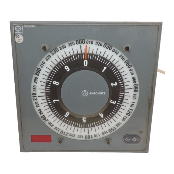
Operator manual REPEATER 133--560 Construction 1.2.1 Front panel An anti--reflective polyester screen covers the cards on the front panel of the Repeater Compass. The lubber line is inside the plate. LEDs illuminate the lubber line and the cards in an area of ± 55°. In the lower area of the front plate on the right side (refer to Fig. 2) a LED ligths up in three colors. -
Page 8: Stepping Motor Assembly
Operator manual 1.2.2 Stepping motor assembly (Refer to Fig. 3) The two cards are driven by a stepping motor each. The shaft of the stepping motor for the 10° card is arranged centrically in the shaft of the stepping motor for the 360° card. The cards are directly mounted on the shafts of the stepping motors. -
Page 9: Principle Of Operation
The serial course information is converted into steps on the steering repeater PCB for the stepping motor in the ration of 1 : 36 and is shown by the 360° and the 10° card. *) “Raytheon Marine” specific Edition: July 06, 2005... -
Page 10: Function Keys
Operator manual 1.3.1 Function keys Various functions can be selected via two keys on the right side of the front panel: -- 1. Function: DIMMING (see section 2.7.1) This function is available in the normal operation mode. It is not specially indicated. - Page 11 Operator manual REPEATER 133--560 -- 5. Function: CORRECTION of the Analog Indications (Cards) (see section 2.7.3) NOTE! The analog indications are adjusted by the manufacturer. A correction of the analog indications is not needed in nor- mal operation. The correction is required in the case of de- synchronisation of the analog and digital display only.
-
Page 12: Technical Data
Operator manual Technical data 1.4.1 Dimensions and weight For dimensions, weights and types of enclosures refer to the dimensional drawings in the annex: Part No. Drawing No. Designation 133--560 NG001 133--560.HP005 Repeater Compass for flush mounting (standard) 133--560 NG003 133--560.HP010 Repeater Compass for bulkhead mounting 133--560 NG004 133--560.HP011 Repeater Compass for wall mounting 133--560 NG005 133--560.HP012 Repeater Compass for bulkhead mounting 133--560 NG006 133--560.HP013 Repeater Compass for flush mounting + casing... -
Page 13: Operating Of The Repeater Compass Type 133 - - 560
Operator manual REPEATER 133--560 Operating of the Repeater Compass Type 133 - - 560 Indications 2.1.1 Analog heading indication The serial course information is converted into steps on the steering repeater PCB for the stepping motor in the ratio of 1 : 36. It is indicated by the 360° and the 10° card. 2.1.2 Digital heading display In addition to the analog heading indication by the cards, the Repeater Compass is also... -
Page 14: Notes On The Operating Instructions
Operator manual Notes on the operating instructions Follow step by step the operating procedure shown in the corresponding sections. If necessary, helpful information in short form has been added to the figurative representa- tion (symbols). Explanation of the manual symbols: Key operation Action, general LED off... -
Page 15: Switching On The Repeater Compass
Operator manual REPEATER 133--560 Switching on the Repeater Compass When the supply voltage is switched on, the Repeater Compass is put into operation. After switching on the Repeater Compass an automatical synchronisation follows. The current heading is shown by the analog and digital indications. The digital display alternates between the current heading indication and the current type of the heading sensor every 30 seconds. -
Page 16: Indication Of The Repeater Compass After Putting Into Operation
Numerical heading indication Indications during GPS compass operation If the Repeater Compass is used with a Raytheon GPS compass the heading indication is available after the alignment stage (approx. 10 to 15 minutes). If the connection between the GPS compass and the corresponding satellite is disturbed, no heading indication is available. -
Page 17: Signals During Operation
Operator manual REPEATER 133--560 Signals during operation During normal operation the heading is indicated by the display and the cards. In addition to the heading value on the digital display every 30 seconds, the current type of the heading sensor is indicated on the display. During this time the display flashes for approx. 5 se- conds. -
Page 18: Additional Operations During Normal Mode
Operator manual Additional operations during normal mode 2.7.1 Dimming Indications Comments, notes Continuous brightness adjustment of the scale illumination the display illumination ” ” darker ” ” brighter The brightness level of the lubber line remains unchanged. Edition: July 06, 2005 3649.DOC010102... -
Page 19: Test
Operator manual REPEATER 133--560 2.7.2 Test With the operation described below the test mode is started. Indications Comments, notes Do not operate both keys for too long: after approx. 8 seconds the service mode (Addr.) is started after approx. 10 seconds the con-- figuration mode (--CF--) is started. -
Page 20: Correction Of The Analog Indications (Cards)
Operator manual 2.7.3 Correction of the analog indications (cards) The correction of the analog indications is required, if: -- the value of the cards does not correspond to the value on the digital display. -- the adjustments of the manufacturer are lost. -- this is only caused by a step fault of the stepping motor and not by an interruption of the heading transmission or an interruption of the power supply. -
Page 21: Fault Operation
4.2.2. Effect: The heading indication on the digital display does not correspond to the heading of the ship. Measures: Check connections, or call Raytheon Marine service. Indications Comments, notes LED lights up red continuously and cannot be dimmed. -
Page 22: Service Mode
Operator manual Service mode In the service mode the current adjustments, the configuration and the software version of the Repeater Compass can be read--out. In this mode the adjustments cannot be changed (refer to section 3.3). After operating no key for approx. 5 seconds the Repeater Compass changes to normal operation mode automatically. - Page 23 Operator manual REPEATER 133--560 Indications Comments, notes (yellow) Indication of the software version Version of the program: State of development: 0.0. operate right key (yellow) CAN Bus address The CAN Bus address is determined by the manufacturer. This function is not applicable. operate right key Heading sensor...
- Page 24 End / beginning of the service mode (yellow) After operating no key for approx. 5 s the display changes to normal operation automatically. operate right key *) “Raytheon Marine” specific Edition: July 06, 2005 3649.DOC010102...
-
Page 25: Switching Off The Repeater Compass
Operator manual REPEATER 133--560 2.10 Switching off the Repeater Compass The Repeater Compass is switched off by switching off the supply voltage. Edition: July 06, 2005 3649.DOC010102... - Page 26 Operator manual Edition: July 06, 2005 3649.DOC010102...
-
Page 27: Installation Of The Repeater Compass
Operator manual REPEATER 133--560 Installation of the Repeater Compass General WARNING! Before establishing the cable connection the supply voltage must be switched off. Ensure that the supply voltage cannot be switched on during installation. CAUTION! Do not open the Repeater Compass when mounting it or during the normal operation. -
Page 28: Electrical Installation Of The Repeater Compass
Operator manual 3.1.2 Electrical installation of the Repeater Compass The supply cable of the Repeater Compass that has to be connected to the ships mains and the heading interface is already connected to the terminal strip inside the repeater. It is fixed in the cable entry of the repeaters casing. -
Page 29: Configuration
Operator manual REPEATER 133--560 Configuration CAUTION! Configure the Repeater Compass very carefully. A false or invalid configuration leads to malfunction and error indications. 3.3.1 General After installation and putting into operation the Repeater Compass must be configured according to the equipment once. Edition: July 06, 2005 3649.DOC010102... - Page 30 Operator manual Indications Comments, notes (green) (yellow) Operate both keys simultaneously for approx. 10 seconds until the display indicates “--CF--” simultaneously (yellow) (yellow) After reaching the configuration mode (CF) the Repeater Compass can be adjusted. After approx. 5 seconds of no operation the configuration mode ends and the current adjust- ments are stored automatically.
-
Page 31: Adjustments In The Configuration Mode (Cf)
“G_AL” (Course bus only) Repeater Compass as steering repeater for gyro com- pass equipment without external operator with alarm indicator. Heading is transmitted by a gyro compass or Raytheon GPS compass. “G_M_” Repeater Compass for gyro, magnetic or GPS compass. - Page 32 Operator manual Current Indications Comments, notes “G_--_” Repeater Compass for gyro or GPS compass. “M_--_” Repeater Compass for magnetic compass. Normal heading indication (no offset). Heading indicating shifted by 180° (offset for special applications). “EHd7” NMEA telegram “HEHDT” Heading course transmitted from gyro compass. “--Hd7”...
- Page 33 Operator manual REPEATER 133--560 Current Indications Comments, notes “CHd7” Magnetic compass telegram “HCHDT” Heading course transmitted from a magnetic compass (not corrected). “CHdG” Magnetic compass telegram “HCHDG” Heading course transmitted from a magnetic compass (corrected). “--HdG” Magnetic compass telegramm “----HDG” Heading course transmitted from a magnetic compass without “talker”.
-
Page 34: Adjustment Of The Course Bus Parameter
Operator manual 3.3.3 Adjustment of the course bus parameter The parameter 1 to 6 in the table in section 3.3.2 configure the course bus operation. With the parameter in 7 to 14 the current types of NMEA telegrams are selected. The adjustments of the parameter 7 to 14 do not influence the Repeater Compass in course bus operation. - Page 35 (”G_M_”) system compass is a gyro com- pass (”G_--_”) system compass is a magnetic compass (”M_--_”) system compass is a Raytheon GPS compass NOTE: Only one telegram is valid. “PHd7”: Heading transmitted from a GPS...
- Page 36 “talker”: system compass is a gyro or ma- gnetic compass (”G_M_”) system compass is a magnetic compass (”M_--_”) system compass is a Raytheon GPS compass “--CHdM”: Heading transmitted from any magnetic compass: system compass is a magnetic compass (”M_--_”)
- Page 37 Operator manual REPEATER 133--560 Maintenance and shipboard repair Maintenance The Repeater Compass requires no special care and maintenance. The analog indication (cards) has to be checked frequently. The indication has to corre-- spond to the digital indication. If the indications differ, switch off the supply voltage and restart the Repeater Compass.
- Page 38 Operator manual 4.2.2 Measures in case of alarms on the Repeater Compass The possible alarms of the Repeater Compass are indicated as error codes on the digital display of the Repeater Compass. Error code Error type Possible cause Measures No or false Fault of the electronic.
- Page 39 Operator manual REPEATER 133--560 Error code Error type Possible cause Measures Analog Desynchronisation of Correction of the analog Stepping fault of one step- indication does analog and digital indication. indications ping motor. (refer to section 2.7.3) not correspond to the digital indication Shaft of the analog Exchange the Repeater...
- Page 40 Operator manual Edition: July 06, 2005 3649.DOC010102...