Table of Contents
Advertisement
Quick Links
Advertisement
Table of Contents

Related Manuals for Delta DVPDT02-H2


Summary of Contents for Delta DVPDT02-H2
- Page 1 DVPDT02-H2 DeviceNet Slave Communication Module Operation Manual DVP-0205120-02...
-
Page 3: Table Of Contents
(e.g. key or specific tools are required for operating the enclosure) in case danger and damage on the device may occur. DVPDT02-H2 is to be used for controlling the operating machine and equipment. In order not to damage it, only qualified professional staff familiar with the structure and operation of DVPDT02-H2 can install, operate, wire and maintain it. - Page 4 LED INDICATORS & TROUBLE-SHOOTING ................. 20 POWER LED ........................20 NS LED..........................20 MS LED ..........................20 NS LED + MS LED ....................... 21 APPENDIX A: DEVICENET OBJECTS DVPDT02-H2 SUPPORTS ............21 APPENDIX B: DEVICENET OJECTS DEFINED BY DVPDT02-H2............24 DVP-PLC Operation Manual...
-
Page 5: Introduction
DeviceNet Slave Communication Module DVPDT02-H2 Introduction 1. To ensure correct installation and proper operation of DVPDT02-H2, please read this chapter carefully before using your DVPDT02-H2. 2. This chapter only provides introductory information on DVPDT02-H2. Details of DeviceNet protocol are not included. -
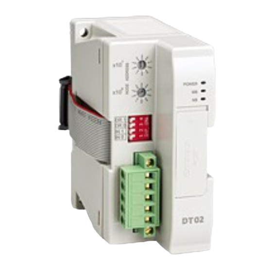
Page 6: Product Profile & Outline
DeviceNet Slave Communication Module DVPDT02-H2 Product Profile & Outline Dimension POWER DR 1 DR 0 IN 1 IN 0 Unit: mm [inch] Product Profiles POWER DR 1 DR 0 IN 1 IN 0 1. I/O module connection port 6. NS (Network Status) indicator 2. -
Page 7: Devicenet Connection Port
Valid DeviceNet node address 64~ 99 Invalid DeviceNet node address Example: If you need to set the node address of DVPDT02-H2 to 26, simply switch the corresponding switch of x10 to 2 and the corresponding switch of x10 to 6. -
Page 8: I/O Module Connection Port
Use slotted screwdriver to adjust the switch carefully in case you scratch the switch. I/O Module Connection Port The I/O module connection port on DVPDT02-H2 is used for the connection to the next DVPDT02-H2 or I/O modules of DVP-EH2 series PLC MPU. -
Page 9: Connecting To Devicenet Connection Port
The colors of the PINs on the DeviceNet connection port match the colors of the connection cables. Make sure you connect the cable to the right PIN. We recommend you also apply Delta’s power module in the connection. Configurating DVPDT02-H2 Format of Request Message and Response Message 1. -
Page 10: Control Registers (Cr) In Dvpdt02-H2
Displaying the current firmware version in hex, e.g.g version V1.12 is indicated as H’0112. Length of I/O Length of output I/O data Length of input I/O data data Output data Area for storing data from DVPDT02-H2 to DeviceNet #3 ~ #102 Get/Set mappinng master. DVP-PLC Operation Manual... -
Page 11: Error Codes
2. Check if the master operates normally. 1. Make sure DVPDT02-H2 has a unique address. Dup_MAC_ID test has failed. 2. Re-power DVPDT02-H2. Working power in low Check if the power of DVPDT02-H2 and MPU is normal. voltage Entering test mode Re-power DVPDT02-H2. Bus-off Re-power DVPDT02-H2 1. - Page 12 500kbps DVPDT02-H2 500kbps 3. Please check and make sure DVP-EH2 PLC MPU and DVPDT02-H2 module both operate normally. Check also the wiring of the entire network and make sure the power supply on DeviceNet network is normal. Configuring the network by DeviceNet network configuration tool Configuration DVPDT02-H2 1.
- Page 13 DeviceNet Slave Communication Module DVPDT02-H2 3. Set up the communication parameters, e.g. “COM Port”, “Address”, “Baud rate”, and so on, for the PC and DVP-28SV in this dialog box. Parameter Function Default COM port on the PC to be used to...
- Page 14 See the figure below, in which the node address of DVPDNET-SL is 01. 8. Double click on DVPDT02-H2 (node 02), and the “Node Configuration...” dialog box will appear. DVP-PLC Operation Manual...
- Page 15 Configuration of DVPDNET-SL 1. Double click on DNET Scanner (node 01), and the "Scan Module Configuration…” dialog box will appear. You can find the currently available node, DVPDT02-H2, in the list. On the right hand side, there is an empty “Scan List”.
- Page 16 DeviceNet Slave Communication Module DVPDT02-H2 2. Move the slave devices on DeviceNet in the “Available Nodes” list on the left hand side to the “Scan List” > on the right hand side. Select a node and click on . Follow the steps to move all the nodes to the scan list.
- Page 17 “Warning” dialog box will appear. 5. Click on “OK” to continue the download. 6. Make sure DVP-SV is in RUN mode. You will then see the MS LED and NS LED on DVPDT02-H2 are steadily on in green color.
- Page 18 DeviceNet Slave Communication Module DVPDT02-H2 Register in CR in DVPDT02-H2 DVPDNET-SL D6294 CR#110 D6295 CR#111 D6296 CR1#12 D6297 CR1#13 D6298 CR#114 D6299 CR#115 D6300 CR#116 D6301 CR#117 D6302 CR#118 DVPDT02-H2 → DVPDNET-SL Register in CR in DVPDT02-H2 DVPDNET-SL D6037 CR#3...
-
Page 19: Application Example Ii
D6048 CR#14 D6049 CR#15 D6050 CR#16 D6051 CR#17 D6052 CR#18 Use DFROM/DTO instruction instead of FROM/TO instruction. Application Example II The default I/O data length of DVPDT02-H2 is 32 bytes. The configured I/O data length of DVPDT02-H2 DVP-PLC Operation Manual... - Page 20 DeviceNet Slave Communication Module DVPDT02-H2 through DeviceNet network configuration tool is 200 bytes. Constructing DeviceNet network: DVPDNET-SL DVP28SV DVPDNET DVP28SV DeviceNet network configuration tool STOP Master POWER STOP ERRO R BAT.L OW DVP-20EH DeviceNet 1. Scan the DeviceNet network by DeviceNetBuilder. After the scan is completed, the nodes on the DeviceNet network will appear on the screen.
- Page 21 3. Select “Parameter Edit…”, and the "Parameter Edit..." window will appear. 4. Set the “Input IO Data Length” and “Output IO Data Length" to 200 bytes. 5. Click on “Download” to download the I/O data configuration to DVPDT02-H2 and re-power DVPDT02-H2. DVP-PLC Operation Manual...
-
Page 22: Led Indicators & Trouble-Shooting
DeviceNet Slave Communication Module DVPDT02-H2 LED Indicators & Trouble-shooting There are 3 LED indicators on DVPDT02-H2. POWER indicator displays the status of working power. NS indicator and MS indicator display the connection status of the communication. POWER LED LED status... -
Page 23: Ns Led Ms Led
NS LED + MS LED LED status Indication How to correct NS LED MS LED Check the power of DVPDT02-H2 and see if the No power connection is normal. DVPDT02-H2 has not Make sure at least one or more nodes on the Green light... - Page 24 DeviceNet Slave Communication Module DVPDT02-H2 Attribute ID Access rule Name Data type MaxRev USINT MinRev USINT Status WORD UDINT ProdName StrLen USINT ASCIIStr STRING Common services Implemented for Service code Service name Class Instance 0x05 Reset 0x0E Get_Attribute_Single Class 0x02 – Message router object...
- Page 25 DeviceNet Slave Communication Module DVPDT02-H2 Attribute ID Access rule Name Data type BaudRateSwitchChanged BOOL MACIDSwitchValue USINT BaudRateSwitchValue USINT Common services Implemented for Service code Service name Class Instance 0x0E Get_Attribute_Single 0x10 Set_Attribute_Single 0x4B Allocate_Master/Slave_Connection_Set 0x4C Release_Master/Slave_Connection_Set Class 0x05 – Connection object...
-
Page 26: Appendix B: Devicenet Ojects Defined By Dvpdt02-H2
Service name Class Instance 0x05 Reset 0x0E Get_Attribute_Single 0x10 Set_Attribute_Single Appendix B: DeviceNet Ojects Defined by DVPDT02-H2 Class 0x95 – DVPDT02-H2 I/O data configuration object Class attribute Attribute ID Access rule Name Data type Revision UINT Instance 1: Model code Attribute... - Page 27 DeviceNet Slave Communication Module DVPDT02-H2 Attribute Access Name Range Default Explanation rule Unit: byte Polling path of the parameter value. Connection path Max. connection path: 255 bytes Descriptor 0 ~ 127 The descriptor of parameter Data type 1 ~ 8...
- Page 28 DeviceNet Slave Communication Module DVPDT02-H2 Attribute Access Name Range Default Explanation rule The length of connection path (Attribute 3). “0” refers to the Length of connection path is not designated. connection path Unit: byte Polling path of the parameter value.