Table of Contents
Advertisement
Quick Links
Advertisement
Table of Contents

Related Manuals for Delta DVPEN01-SL


Summary of Contents for Delta DVPEN01-SL
- Page 1 DVPEN01-SL Ethernet Communication Module Operation Manual DVP-0204320-04...
-
Page 3: Table Of Contents
LED Indicators .......................... 4 RJ-45 PIN Definition ......................... 5 INSTALLATION & WIRING ........................ 5 Installation ..........................5 Connecting DVPEN01-SL to the Network: ................6 CONTROL REGISTER (CR) ......................6 Control Registers in DVPEN01-SL ................... 6 Explanations on CR ........................8 Numbering of Left-Side Modules .................... - Page 4 APPLICATION EXAMPLES ......................34 Setting an IP Address and Communication through WPLSoft ..........34 Connecting the PC with DVPEN01-SL through LAN ............... 36 Setting a Password and Clearing a Password ................ 38 When the Password is Lost (Returning to Default Setting by RS-232) ........41 IP Filter Protection ........................
-
Page 5: Introduction
DVPEN01-SL is an Ethernet communication module for remote setting and communication through WPLSoft. DVPEN01-SL is able to send E-mails, automatically correct the RTC in DVP28SV11R/T and exchange data. It supports MODBUS TCP communication protocol and can conduct remote monitoring by using SCADA (Supervisor Control and Data Acquisition) software or HMI (Human Machine Interfaces). -
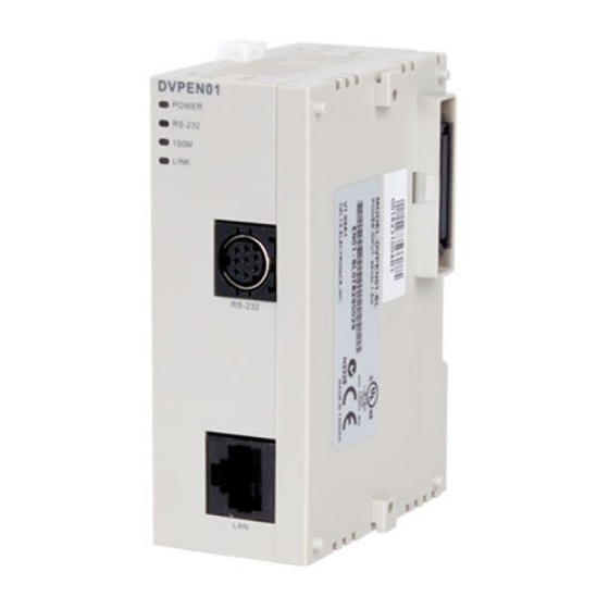
Page 6: Product Profile & Outline
Ethernet Communication Module DVPEN01-SL Electrical specifications Item Specification Power supply voltage 24VDC (-15%~20%) (Power is supplied by the internal bus of MPU.) Power consumption 1.5W Insulation voltage 500V Weight (g) 92 (g) Product Profile & Outline 2.1 Dimension 3 [0.118]... -
Page 7: Pin Definition
DVP28SV POWER RS-232 100M LINK RS-232 Connecting DVPEN01-SL to other I/O modules: To connect DVPEN01-SL with the other I/O module, lift the extension clip of the I/O module by a screwdriver and open the side cover. DVP-PLC Operation Manual... -
Page 8: Connecting Dvpen01-Sl To The Network
Ethernet Communication Module DVPEN01-SL 3.2 Connecting DVPEN01-SL to the Network: Connect DVPEN01-SL to the Ethernet Hub by twisted pair cable CAT-5e. DVPEN01-SL has Auto MDI/MDIX function; therefore, DVPEN01-SL does not need to use a crossing cable between the PC and DVPEN01-SL. - Page 9 Ethernet Communication Module DVPEN01-SL Attribute Content Explanation Data exchange cycle The control register is used to set data exchange cycle time. The time unit used is a millsecond. 0: No error occurs. Error status of slaves in 1: An error occurs in data exchange.
-
Page 10: Explanations On Cr
You can read the model code in the program to see if the I/O module exists. CR #1: Firmware version Explanations: The firmware version of DVPEN01-SL is displayed in hex, e.g. H’0100 indicates version V1.00. CR #2: Communication mode Explanations: Bit No. - Page 11 Ethernet Communication Module DVPEN01-SL CR #9 ~ 1 2: E-mail 1~4 additional message Explanations: The user fills in the code, and the code will be stored in the title of the E-mail and sent out with the E-mail. Data Exchange ...
- Page 12 Explanations: When you set the Salve ID (i.e. K1~K255) for data exchange, DVPEN01-SL will automatically search for the corresponding IP address from the slave IP address list. For example, if the ID is set as “0”, the value in CR#25 and #26 will be regarded as the destination IP address.
- Page 13 D8~D11 of the Master will be written into D2~D5 of the Slave. Both sending and receiving can be executed at the same time. When the values in CR#82 and #85 are both “0”, DVPEN01-SL will use the default registers DVP-PLC Operation Manual...
- Page 14 Ethernet Communication Module DVPEN01-SL (CR#29~CR#68) and number of registers (K20). Setting an IP address CR #8 7: Mode of setting an IP address Explanations: 0: Static IP address 1: DHCP CR #8 8 ~ 89 : IP address Explanations: The control registers are used to set an IP address.
- Page 15 CR#112 is the TCP Keepalive timeout for MODBUS TCP connection. (Unit: Second) Default: 30s If the connection idle time becomes longer than the keep-alive time-out, DVPEN01-SL will cut off the idle connection. CR # 11 4: MODBUS TCP timeout Explanations:...
-
Page 16: Numbering Of Left-Side Modules
4.3 Numbering of Left-Side Modules After DVPEN01-SL is installed properly, you need to compile the PLC program to control the special I/O module. PLC offers FROM instruction (for reading) and TO instruction (for writing) to control the control registers (CR) in the special I/O module. -
Page 17: Setting The Software
Ethernet in the Communication Setting window. Next, you can search by IP address or use Auto-Search. You also can open the setup page for DVPEN01-SL by RS-232. DVPEN01-SL is set by UDP port 20006;... - Page 18 1. Click Search in DCISoft to search for all Delta Ethernet products on the network. The window on the left hand side shows the models found, and the window on the right hand side displays the device list of all models.
- Page 19 Ethernet Communication Module DVPEN01-SL 3. You will see the basic setup page as follow. Designating a model to search 1. Right click Ethernet on the left hand side window and click Configure to designate a model to search for.
- Page 20 Ethernet Communication Module DVPEN01-SL 2. After configure a model, select the DVPEN01-SL checkbox and click OK to auto-search for DVPEN01-SL modules on the network. 3. List of the current DVPEN01-SL modules DVP-PLC Operation Manual...
- Page 21 Ethernet Communication Module DVPEN01-SL Searching by an IP address 1. Select Ethernet in the Communication Type section, and enter the IP address. Click OK. 2. Click IP Search to start searching for the designated IP address. DVP-PLC Operation Manual...
- Page 22 Ethernet Communication Module DVPEN01-SL 3. The DVPEN01-SL module found will be displayed in the right hand side window. Double click it to enter the setup page. Opening the DVPEN01-SL setup page by RS-232 1. Select RS232 as the transmission type in the Communication Setting window. You will have to designate a communication port.
-
Page 23: Basic Settings
Basic settings 1. Module Name There can be many DVPEN01-SL modules in the network. Thus, you can set a module name for each module to identify the module when you need to use them. 2. Module Language You can select a language for each module name, and the windows will be displayed in the selected language. -
Page 24: Network Settings
You should choice the Time zone that you are. 8. Protocol Select DVPEN01-SL supports MODBUS TCP and the Mitsubishi MELSEC protocol in a UDP mode. The defatul setting is MODBUS TCP. 5.3 Network Settings The first step for all the network equipment to connect to the network is to have its own IP address (Internet Protocol). - Page 25 Ethernet Communication Module DVPEN01-SL 2. You will see the Local Area Connection Status window. Click on Properties. 3. Click on Internet Protocol (TCP/IP). 4. Enter 192.168.0.1 into the IP address box. Click on OK to complete the IP address setting of the PC.
- Page 26 For example, if the LAN has to be connected to WAN, it will need a gateway to bridge the communication. The IP address of the gateway has to be in the same subnet as DVPEN01-SL. The default gateway IP address of DVPEN01-SL is 192.168.1.1.
-
Page 27: Setting E-Mails
DVPEN01-SL offers 4 sets of E-mail information, and you can self-define the register or bit information to be read. When the trigger occurs, DVPEN01-SL will add the set register or bit present value read to the E-mail. Every piece of E-mail information is able to contain the present values in the up to 100 consecutive registers. -
Page 28: Snmp
SMTP server first, and the server will further send the mail to the designated address. 5.5 SNMP SNMP is a simple network management function. Users can read and control the registers in a PLC by means of a SNMP network management tool. (DVPEN01-SL version 2.06 and above support this function.) Setting ... -
Page 29: Data Exchange
3. Station Address and IP Address You have to enter the IP address of DVPEN01-SL at the other end. For example, if you would like DVPEN01-SL to exchange data with 192.168.0.1, set No. 1 as 192.168.0.1. When the data are being exchanged, if the value in CR#28 is H’0001, the data will be exchanged with 192.168.0.1. -
Page 30: Melsec Protocol
Ethernet Communication Module DVPEN01-SL MELSEC Protocol DVPEN01-SL can communicate with Mitsubishi devices by means of the MELSEC protocol. It can support the communication with a master and the communication with slaves simultaneously. Only UDP communication is allowed. (DVPEN01-SL version 2.10 and above support this function.) Setting the MELSEC protocol mode ... - Page 31 For example, the users can type the slave ID 1 and the IP address 192.168.0.1. If data exchange is executed, DVPEN01-SL will exchange data with the device whose slave ID is 1 and whose IP address is 192.168.0.1 by means of the MELSEC communication.
-
Page 32: Rtu
Use the RTU function to conduct mapping between Delta’s network modules DVPEN01-SL and RTU-EN01.Set the mapping information first, and you will be able to use WPLSoft in DVPEN01-SL to save and retrieve the mapped bit (M) and register (D) in order to operate the remote RTU-EN01. -
Page 33: Ip Filter
Ethernet Communication Module DVPEN01-SL 5.9 IP Filter An IP filter is used for restricting the connection of the network in case some uncertain IP addresses will cause errors. Only the IP addresses set within a certain range can establish a connection. Other IP addresses will be rejected. -
Page 34: Setting A Password
Incorrect settings may result in connection failure. Therefore, DO NOT set the MAC address of the equipment without the network into the table. 5.11 Setting a Password To prevent the set values in DVPEN01-SL from being modified, you can set a password to lock the settings in DVPEN01-SL. Setting the DVPEN01-SL password ... -
Page 35: Returning To Default Settings
Note: If you set DVPEN01-SL by RS-232, you can return the setting to default setting whether the password is locked or not. It takes approximately 10 seconds to return to default setting, so DO NOT switch off the power within the 10 seconds. -
Page 36: Application Examples
(3) IP address of DVPEN01-SL: 192.168.0.4 (4) Connect the PC and DVPEN01-SL by RJ-45 cable. Note: Both PC and DVPEN01-SL have to adopt a static IP address. 1. The connection 2. Start WPLSoft, and click Ethernet in the Communication Setting Section. - Page 37 Ethernet Communication Module DVPEN01-SL 4. All the devices connected to the network are shown in the Ethernet section. After DELTA DVPEN01-SL is clicked, WPSoft can communicate with the MPU by means of DVPEN01-SL. 5. After DELTA DVPEN01-SL in the Ethernet section is double-clicked, DCISoft will be started. Please refer to section 5.3 for more infomrationa bout setting an IP address.
-
Page 38: Connecting The Pc With Dvpen01-Sl Through Lan
Application Setting the network parameters of DVPEN01-SL by WPLSoft through LAN. Network (1) Connect the PC and DVPEN01-SL by using DHCP server through LAN. environment (2) IP address of DVPEN01-SL: 172.16.157.148 Note: DVPEN01-SL can use a RJ-45 cable with/without a jump wire. - Page 39 3. Click Auto-Search Ethernet Module to search for all the Ethernet modules on the network. 4. All the devices connected to the network are shown in the Ethernet section. After DELTA DVPEN01-SL is clicked, WPSoft can communicate with the MPU by means of DVPEN01-SL.
-
Page 40: Setting A Password And Clearing A Password
Ethernet Communication Module DVPEN01-SL 5. After DELTA DVPEN01-SL in the Ethernet section is double-clicked, DCISoft will be started. Please refer to section 5.3 for more infomrationa bout setting an IP address. 6. After the setting of an IP address is complete, and step 2~step 4 are repeated, the IP address can be used for communication. - Page 41 Ethernet Communication Module DVPEN01-SL 3. Select the Modify checkbox, and enter “aabb” in the Password box and the Confirm Password box. Click on OK to save the password. DVP-PLC Operation Manual...
- Page 42 Ethernet Communication Module DVPEN01-SL 4. Open the setup page again, and DVPEN01-SL is now locked by the password. You cannot open any of the settings now. Click on Confirm to leave the entering password window. 5. Enter the password to temporarily unlock the protection and modify the parameters. If you close the setup page, the locking will automatically be recovered.
-
Page 43: When The Password Is Lost (Returning To Default Setting By Rs-232)
Returning to default setting by RS-232 Network (1) DVPEN01-SL is set with a password. environment (2) The password is forgotten. 1. Use DVPACAB2A30 cable to connect the PC and DVPEN01-SL and open the setup page. Open the Security page. DVP-PLC Operation Manual... -
Page 44: Ip Filter Protection
6.5 IP Filter Protection Application Setting the IP filter protection Network (1) IP address of DVPEN01-SL: 192.168.0.4 environment (2) Only connections to 192.168.0.7 and 172.16.0.1~172.16.0.255 are allowed. 1. See 6.1 for the connection and how to set the communication. 2. Open the setup page and switch to the IP Filter page. - Page 45 Ethernet Communication Module DVPEN01-SL 3. Select the Enable IP Filter checkbox. Enter “192.168.0.4” in the No. 1 IP Address box and “255.255.255.255” in the No. 1 Subnet Netmask box. 4. Enter “192.168.0.1” in the No. 2 IP Address box and “255.255.255.0” in the No.2 Subnet Netmask box. Click on OK to complete the setting.
-
Page 46: Setting A Static Arp Table
Ethernet Communication Module DVPEN01-SL 6.6 Setting a Static ARP Table Application Setting a static ARP table Network (1) MAC address of equipment 192.168.1.6 is 00:18:23:10:00:35 environment (2) MAC address of equipment 192.168.1.1 is 00:18:23:10:00:04 1. See 6.1 for the connection and how to set the communication. - Page 47 Only the equipment within the IP address range can be connected. Note: The MAC address of DVPEN01-SL can be obtained from WPLSoft or the MAC address sticker on the equipment. The MAC address of PC can be found in the Network Connection Details widow (see below).
-
Page 48: Application Of E-Mails
Ethernet Communication Module DVPEN01-SL 6.7 Application of E-mails Application Sending an E-mail to notify the administrator when the current status of X0 and Y0 is changed. Network (1) IP address of the SMTP server: 172.16.144.121 application (2) E-mail address of administrator: test@sample.com (3) An E-mail message will be generated when the status of X0 and Y0 is changed. -
Page 49: Application Of Data Exchange (1)
K100 Explanations: • If the rising-edge of X0 is triggered, X0 will go from Off to On. Write “1” into CR#3 of DVPEN01-SL, and the first E-mail will be sent out. • If the falling-edge of X0 is triggered, X0 will go from On to Off. Write “1” into CR#4 of DVPEN01-SL, and the second E-mail will be sent out. - Page 50 Ethernet Communication Module DVPEN01-SL 2. Open the setup page of PLC_B and switch to the Data Exchange page. 3. Select the Enable Data Exchange checkbox. Select Program Control in the Enable Confition drop-down list box. Enter the IP address of PLC_A “192.168.0.4” in the IP Address cell corresponding to station address 1.
-
Page 51: Application Of Data Exchange (2)
• The data exchange will be executed every one second. • Write the communication address of the destination PLC in CR#28, and DVPEN01-SL will automatically detect by the previous setting that No. 1 IP address is “192.168.0.4". • Write the data in RTC into CR#29~CR#35. - Page 52 Ethernet Communication Module DVPEN01-SL (1) Adopt a static IP address. (2) IP address of PLC_A: 192.168.1.99 Network environment (3) IP address of PLC_B: 192.168.1.97 (4) Update from PLC_A to PLC_B and PLC_B to PLC_A. 1. See 6.1 for how to set the communication.
-
Page 53: Application Of Data Exchange (3)
Ethernet Communication Module DVPEN01-SL 6.10 Application of Data Exchange (3) Firmware version 2.0 and above support this function. Enable a timer (X20) and write the timer values into D0~D99. Control the program (X21) and write the Application present values in D0~D99 of PLC_A into D0~D99 of PLC_B, and write the values in D0~D99 of PLC-B into D200~D299 of PLC_A. -
Page 54: Application Of Data Exchange (4)
Ethernet Communication Module DVPEN01-SL 4. After all the settings in PLC_A are completed, you have to write a ladder diagram for the MPU and download it to PLC_B. The program designed is like the one shown below. 6.11 Application of Data Exchange (4) - Page 55 Ethernet Communication Module DVPEN01-SL M1000 D100 M1013 K100 K100 HC0A8 K100 K100 D100 K100 K100 FROM K100 = D14 K2 = D14 K3 Explanations: • The data exchange will be executed every one second. • Write “0” into CR#28, and PLC_B will use CR#25~CR#26 as the IP address of the destination PLC.
-
Page 56: Application Of Data Exchange (5)
Ethernet Communication Module DVPEN01-SL 6.12 Application of Data Exchange (5) Writing the time in RTC in PLC_B directly into D0~D6 of PLC_A without writing in ladder diagram into Application PLC_A. Network (1) Adopt a static IP address. environment (2) IP addres of PLC_A: 192.168.0.4 (3) IP address of PLC_B: 192.168.0.5... -
Page 57: Application Of Modbus Tcp Master
Ethernet Communication Module DVPEN01-SL • Write the IP address of PLC_A into CR#25 and CR#26. The first two IP codes (192.168=H’C0A8) should be written into CR#26, and the last two IP codes (0.4=H’0004) into CR#25. • Write the MODBUS address of D0 (H’1000) in PLC_A into CR#81 and CR#84. -
Page 58: Rtu Mapping
(5) Set the mapping start address and number of data for RX, RY, RCR (read) and RCR (write) at DVPEN01-SL. (6) Enable the mapping function in DVP-SV PLC at DVPEN01-SL. Use M2000 and D2000 in DVP-SV to read and M3000 and D3000 to write the value in the remote RTU-EN01. - Page 59 3. Use DCISoft for DVPEN01-SL to set start addresses and numbers. (RX: M2000~M2009; RY: M3000~M3009; RCR (Reading): D2000~D2009; RCR (Writing): D3000~D3009) 4. Edit a ladder diagram, and download it to DVPEN01-SL. The program edited is like the one shown below. DVP-PLC Operation Manual...
-
Page 60: Application Of The Melsec Protocol
Communication port: 9002 3. Write a program for the MPU, and download it to DVPEN01-SL. The program designed is like the one shown below. 4. Use DCISof to set data exchange for DVPEN01-SL. ※ After the settings are downloaded, DVPEN01-SL will read the data in D0~D99 in the Mitsubish PLC into D0~D99 in DVP28SV, and write the data in D100~D199 in DVP28SV into D100~D199 in the Mitsubish PLC.