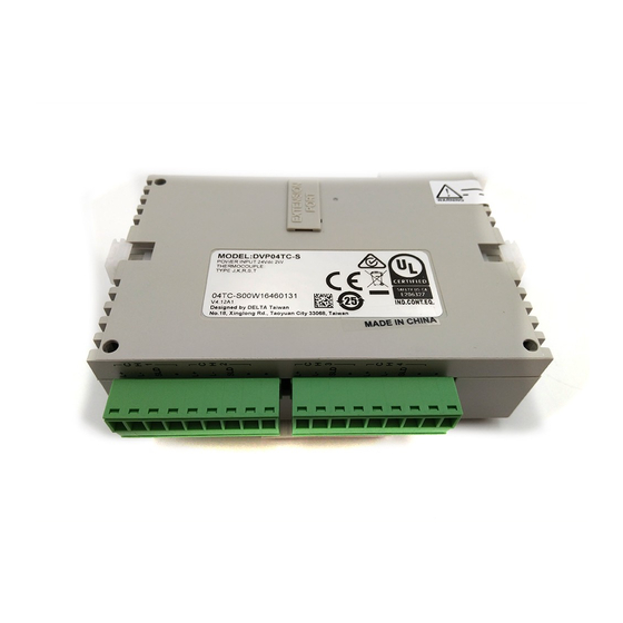
Delta DVP04TC-S Instruction Sheet
Temperature measurement module
Hide thumbs
Also See for DVP04TC-S:
- Instruction sheet (2 pages) ,
- Instruction sheet (2 pages) ,
- Instruction sheet (16 pages)
Advertisement
Available languages
Available languages
Quick Links
Advertisement

Related Manuals for Delta DVP04TC-S


Summary of Contents for Delta DVP04TC-S
- Page 1 2018-07-20 5011669910-T410...
- Page 2 FROM/TO instructions in DVP Slim series MPU program, the data in the module can be read and written. There are many 16-bit control registers (CR) in DVP04TC-S. The power unit is separate from it and is small in size and easy to install.
-
Page 3: Electrical Specifications
Note2: Terminal SLD is a grounding location for noise suppression. Note3: Please connect power supply module terminal and DVP04TC-S temperature measurement module terminal to system earth ground. Warning1: Do NOT wire empty terminals. Warning2: Only use copper conducting wires with a temperature rating of 60/75°C and the length must be less than 50 m. -
Page 4: Control Register
Control Register Address Save Register content Description Set up by the system: H’4096 Model name DVP04TC-S model code=H’8B b15~b12 b11~b9 b8~b6 b5~b3 b2~b0 Reserved Example: Setting of CH1 (b2, b1, b0) set to (0, 0, 0), use J-type. H’4097 Thermocouple type (b2, b1, b0) set to (0, 0, 1), use K-type. - Page 5 Set H'5678 to enable PID mode, other set H’40B3 PID mode setting values are invalid. Default: H’0000. Data register stores the error status. Refer to H’40B4 Error status the error code chart for details. Communication address RS-485 communication address. Setting H’40B5 setting range is 1 ~ 254 and default setting is K1.
- Page 6 Note: Each error code will have corresponding bit (b0 ~ b7). Two or more errors may happen at the same time. 0 means normal and 1 means having error. 6. When CR#29 is set to H’5678, CR#0 ~ CR#34 can be used for PID settings in DVP04TC-S V3.08 and versions above.
- Page 7 ……………………………………………………………… 繁體中文 ………………………………………………………………………… 感謝您採用台達 DVP 系列產品。DVP04TC-S 溫度量測模組可接受外部 4 點熱電耦溫度感測器, 將之轉換成 14 位元之數位信號。透過 DVP 薄型系列(Slim type)主機程式以指令 FROM/TO 來 讀寫模組內之資料,模組內具有多個控制暫存器(CR) ,每個暫存器有 16 bits。電源單元與模組 分離,體積小,安裝容易。 請在使用之前,詳細閱讀本使用說明書。實施配線,請務必關閉電源。上電時請勿接觸機體端 子或進行維修。輸入電源切斷後,一分鐘之內,請勿觸摸內部電路。 本機為開放型 (OPEN TYPE) 機殼,因此使用者使用本機時,必須將之安裝於具防塵、防潮 及免於電擊/衝擊意外之外殼配線箱內。另必須具備保護措施(如:特殊之工具或鑰匙才可打 開)防止非維護人員操作或意外衝擊本體,造成危險及損壞。 交流輸入電源不可連接於輸入∕出信號端,否則可能造成嚴重的損壞,因此請在上電之前再次 確認電源配線。 本體上之接地端子 務必正確的接地,可提高產品抗雜訊能力。 由測溫體到溫調本體的配線路請用最短距離配線,為了避免雜訊及誘導的影響儘可能將電源線...
- Page 8 2. 儲存:-25°C ~ 70°C(溫度) ,5 ~ 95%(濕度) 國際標準規範IEC61131-2, IEC 68-2-6 (TEST Fc)/IEC61131-2 & IEC 68-2-27 耐振動/衝擊 (TEST Ea) 與DVP-PLC主機 模組編號以靠近主機之順序自動編號由0到7,最大可連接8台且不佔用數位I/O點 數。 串接說明 功能規格 DVP04TC-S 攝氏 (°C) 華氏 (°F) 4通道∕台 類比訊號輸入通道 J-type, K-type, R-type, S-type, T-type 熱電耦 適合感應器形式 J-type:-100°C ~ 700°C J-type:-148°F ~ 1,292°F K-type:-100°C ~ 1,000°C...
- Page 9 參數 保持型 暫存器名稱 說明 位址 H’409E CH3量測攝氏溫度平均值 H’409F CH4量測攝氏溫度平均值 H’40A0 CH1量測華氏溫度平均值 H’40A1 CH2量測華氏溫度平均值 通道CH1 ~ CH4量測華氏溫度平均值顯示。單 位0.1°F。 H’40A2 CH3量測華氏溫度平均值 H’40A3 CH4量測華氏溫度平均值 H’40A4 CH1量測攝氏溫度現在值 H’40A5 CH2量測攝氏溫度現在值 通道CH1 ~ CH4量測攝氏溫度現在值顯示。單 位0.1°C。 H’40A6 CH3量測攝氏溫度現在值 H’40A7 CH4量測攝氏溫度現在值 H’40A9 CH1量測華氏溫度現在值 H’40AA CH2量測華氏溫度現在值 通道CH1 ~ CH4量測華氏溫度現在值顯示。單 位0.1°F。...
- Page 10 2. 控制暫存器(CR)之 MODBUS 十進制通訊位址,可由控制暫存器表格中 16 進制通訊位址,轉換成十 進制後再加上 1,即為 MODBUS 十進制通訊位址。Ex: CR#0 之 DVP 通訊位址為 H’4096,而 MODBUS 十進制位址為 16535。 3. CR#32 通訊格式設定說明:韌體版本 V4.12(含)以下,不開放資料格式(b11~b8)選擇,ASCII 固定 為 7, E, 1 格式 (代碼 H’00xx) ,RTU 固定為 8, E, 1 格式 (代碼 H’C0xx/H’80xx) 。韌體版本為 V4.13 (含) 以上,請參考下表設定,並且請注意原先設定代碼...
- Page 11 ………………………………………………………………… 简体中文 …………………………………………………………………… 感谢您采用台达 DVP 系列产品。DVP04TC-S 温度测量模块可接受外部 4 点热电耦温度 传感器,将其转换成 14 位的数字信号。透过 DVP 薄型系列(Slim type)主机程序以指 令 FROM/TO 来读写模块内的数据,模块内具有多个控制寄存器(CR) ,每个寄存器有 16 bits。电源单元与模块分离,体积小,安装容易。 请在使用之前,详细阅读本使用说明书。实施配线,务必关闭电源。上电时请勿接触 机体端子或进行维修。输入电源切断后,一分钟之内,请勿触摸内部电路。 本机为开放型 (OPEN TYPE) 机壳, 因此使用者使用本机时, 必须将其安装于具防尘、 防潮及免于电击∕冲击意外的外壳配线箱内。另必须具备保护措施(如:特殊的工具 或钥匙才可打开)防止非维护人员操作或意外冲击本体,造成危险及损坏。 交流输入电源不可连接于输入∕出信号端,否则可能造成严重的损坏,因此请在上电 之前再次确认电源配线。 本体上的接地端子...
- Page 12 2. 储存:-25°C ~ 70°C(温度) ,5 ~ 95%(湿度) 国际标准规范IEC61131-2, IEC 68-2-6 (TEST Fc)/IEC61131-2 & IEC 耐振动∕冲击 68-2-27 (TEST Ea) 与DVP-PLC主机 模块编号以靠近主机的顺序自动编号由0到7,最大可连接8台且不占用数 串接说明 字I/O点数。 功能规格 DVP04TC-S 摄氏 (°C) 华氏 (°F) 4通道/台 模拟讯号输入通道 J-type, K-type, R-type, S-type, T-type 热电耦 适合感应器形式 J-type:-100°C ~ 700°C J-type:-148°F ~ 1,292°F K-type:-100°C ~ 1,000°C...
- Page 13 参数 保持型 寄存器名称 说明 地址 H’4099 O R/W CH2平均次数 V3.04以前版本: 可设定范围K1 ~ K4,095。 V3.05以后版本:可设定范围K1 ~ K20。 H’409A O R/W CH3平均次数 出厂设定值为K10。 H’409B O R/W CH4平均次数 CR#2 ~ CR#5:注意,当PLC主机利用TO/DTO指令写入的平均次数设定时,请使用接点上升 下降缘检出指令 (LDP/LDF…),以免无法求得正确之输入信号平均值。 H’409C X CH1测量摄氏温度平均值 H’409D X CH2测量摄氏温度平均值 通道CH1 ~ CH4测量摄氏温度平均值显 示。单位0.1°C。 H’409E X CH3测量摄氏温度平均值...
- Page 14 参数 保持型 寄存器名称 说明 地址 2. b13对应CH2,当b13=1时,刻度超过 ERR灯闪烁动作。 3. b14对应CH3,当b14=1时,刻度超过 ERR灯闪烁动作。 4. b15对应CH4,当b15=1时,刻度超过 ERR灯闪烁动作。 16进制,显示目前韧体版本,如1.0A则 #34 H’40B8 O 韧体版本 H’010A。 #35 ~ #48 系统内部使用 符号定义: O表示为保持型;X表示为非保持型。 (利用RS-485通讯控制时支持,连接主机时不支持) R表示为可使用FROM指令读取数据,或利用RS-485通讯读取数据。 W表示为可使用TO指令写入数据,或利用RS-485通讯写入数据。 1. 模块重置(韧体版本 V4.14 以上) :若需要将此模块所有设定重置,首先需确保模块的电源输 入口已连接电源,接着将重置指令 H’4352 写入 CR#0,并断电重启,即完成所有设定的重置。 2. 控制寄存器(CR)之 MODBUS 十进制通讯地址,可由控制寄存器表格中 16 进制通讯地址, 转换成十进制后再加上...
- Page 15 CH2 PID 输出% R/W CH4 K CH3 PID 输出% Run/Stop & Auto tuning CH4 PID 输出% Bit0:CH1 PID Run/Stop CR#2~CR#5:范围:0~1000,单位 0.1% Bit1:CH2 PID Run/Stop CH1 摄氏平均温度 Bit2:CH3 PID Run/Stop CH2 摄氏平均温度 Bit3:CH4 PID Run/Stop CH3 摄氏平均温度 0=PID Stop,1=PID Run CH4 摄氏平均温度 Bit4:CH1 Auto tuning CR#6~CR#9:单位...
- Page 16 DVP04TC-S küçük boyutlu bir ünitedir ve ısı iletkenliği aynı ortamda bulunan ısı kaynağından etkilenebilir. Bu durum ölçülen sıcaklık değerinin doğruluğunu da etkiler. Onun için DVP04TC-S ünitesini bağlı olduğu analog ve/veya dijital modüllerle birlikte yüksek ısı kaynağının bulunduğu yerlerden uzak yerlere kurulması...
- Page 17 PLC terminal vidalarını 1.95 kg-cm (1.7 in-lbs) tork oranında sıkınız. Not 2: Gürültüyü önlemek için SLD terminalini topraklayınız. Not 3: Güç kaynağı modülü terminalinden ve DVP04TC-S modülü toprak terminalinden topraklanmalıdır. Uyarı 1: Boş terminallere tel takmayın. Uyarı 2: Yalnızca 60/75°C sıcaklık derecelendirmesine sahip ve uzunluğu 50 metreden az olan bakır iletken teller kullanın.
- Page 18 Reserve Örnek: CH1 ayarı (b2, b1, b0) değeri (0, 0, 0), ise J- tipi. (b2, b1, b0) değeri (0, 0, 1), ise K- tipi. (b2, b1, b0) değeri (0, 1, 0), ise R- tipi. (b2, b1, b0) değeri (0, 1, 1), ise S- tipi. (b2, b1, b0) değeri (1, 0, 0), ise T- tipi.
- Page 19 ERR LED Örnek: CH1 ayarı 1. b0 ~ b1: Reserve. 2. b2: 1 yapılır ve ürün fabrika ayarlarına resetlenir. ERR LED açıklaması: b12~b15=1111 (default ayarlar) 1. b12 CH1 kanalı: b12=1 ise okunan değer sınırı aştı, ERR LED flash yapar. 2. b13 CH2 kanalı: b13=1 ise okunan değer sınırı...
- Page 20 Not: Her hata kodu bir bite karşılık gelecektir (b0 ~ b7). İki veya daha fazla hata aynı anda meydana gelebilir. “0” normal durumu “1” ise hata olduğunu gösterir.. CR#29 değeri H’5678 ayarlandığı zaman, DVP04TC-S V3.08 ve üzeri versiyonlarda CR#0 ~ CR#34 kontrol registerleri PID ayarları için kullanılabilir.