
Related Manuals for Delta DVPSCM Series


Summary of Contents for Delta DVPSCM Series
- Page 1 DVPSCM Series DVPSCM12-SL Serial Communication Module DVPSCM52-SL BACnet MS/TP Slave Communication Module Operation Manual DVP-0186520-02...
-
Page 3: Table Of Contents
Communication Module DVPSCM12/52-SL Warning This operation manual provides the introduction of specifications, installation, basic operation and setting, and contents related to communication protocols. The module is an open-type device. It has to be installed in the distribution box which is dust-proof, moisture-proof, and free from shock and vibration. - Page 4 6.5.2 BACnet Object ......................30 Application............................31 MODBUS..........................31 7.1.1 Connection between the MODBUS Slave and the Delta Product......32 7.1.2 Connection between the MODBUS Master and the Delta Product......33 Connecting to WPLSoft ......................41 RS-485 ............................. 42 7.3.1 Connecting to the Electricity Meter ................
-
Page 5: Introduction
It is equipped with all the functions of DVPSCM12-SL, and supports the BACnet MS/TP slave communication protocol. It can read/write the BV values or AV values from/into a BACnet MS/TP master. SCMSoft, the setting software of DVPSCM52-SL, is built in Delta communication software DCISoft. Please download DCISoft_v1.08 from Delta website. - Page 6 Communication Module DVPSCM12/52-SL Environmental specifications Item Specifications ESD (IEC 61131-2, IEC 61000-4-2): 8 kV Air Discharge EFT (IEC 61131-2, IEC 61000-4-4): ±1 KV (Communication I/O) Noise immunity CS (IEC 61131-2, IEC 6100-4-6): 0.15 ~ 80 MHz, 3 Vrms RS (IEC 61131-2, IEC 61000-4-3): 80 ~ 100 MHz, 10 V/m, 1.4 ~ 2.0 GHz Operating/Storage Operation: 0 ~ 55°C (temperature);...
-
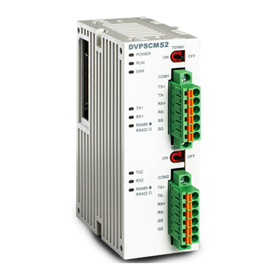
Page 7: Product Appearance And Product Profile
Communication Module DVPSCM12/52-SL 2. Product Appearance and Product Profile 2.1 Dimensions 76.3 [3.004] 60 [2.362] 33.1 [1.303] Unit: mm [inches] 2.2 Product Profile 1. Model name 8. Switch for terminal resistor 1 2. POWER, RUN, ERR LED indicators 9. Extension port for the MPU/left-side module 3. -
Page 8: Led Indicators
Communication Module DVPSCM12/52-SL 2.3 LED Indicators LED indicator Status Indication Disposal Normal power supply No action is required. Green POWER light No power supply Check whether the power supply is on. The status of the SCM module is No action is required. RUN. -
Page 9: Installation And Wiring
Communication Module DVPSCM12/52-SL 3. Installation and Wiring This chapter introduces how an SCM module connects to an MPU 3.1 Installation The MPU of the PLC connects to the SCM module. Adjust the clips connecting to the left-side module on the MPU. Direct the I/O module to the interface on the MPU, and combine the I/O module with the MPU as shown in the figure below. - Page 10 Communication Module DVPSCM12/52-SL MEMO DVP-PLC Operation Manual...
-
Page 11: Control Registers (Cr)
Communication Module DVPSCM12/52-SL 4. Control Registers (CR) 4.1 Table of Control Registers Attribute Name of the register Description The code is set up by the system. Model code Model code of DVPSCM12-SL=H’4041 Model code of DVPSCM52-SL=H’4042 The firmware version is displayed in a hexadecimal value. Firmware version For example, H’0100 indicates that the firmware version is V1.00. -
Page 12: Contents Of Control Registers
Communication Module DVPSCM12/52-SL Attribute Name of the register Description Bit = 0: Disabling the function of reading bits through COM2. Selecting the “reading bits 39~40 through COM2” checkbox Bit = 1: Enabling the function of reading bits through COM2. Bit = 0: Disabling the function of reading words through Selecting the “reading words COM2. - Page 13 Communication Module DVPSCM12/52-SL CR#3:Group number triggered by COM1 UD Link [Description] Enter the Group number edited in UD Link. The data is transmitted through COM1. When the register is set to 1, it indicates that the content of Group ID#1 is triggered and executed. The register is reset to 0 after the execution is complete, and CR#26 is set to 1.
- Page 14 Communication Module DVPSCM12/52-SL CR#8: Reference address of the data sent through COM2 in UD Link [Description] CR#4. Please refer to the description of CR#9: Reference address of the data received through COM2 in UD Link [Description] CR#5. Please refer to the description of CR#10: Module status [Description] The PLC controls RUN/STOP status of the SCM module.
- Page 15 Communication Module DVPSCM12/52-SL CR#32: Triggering the data exchange through COM2 to read bits or words [Description] High byte: COM2 Bit; Low byte: COM2 Word 0: Not triggered; 1: Triggered once; 2: Always triggered Please refer to the table in the description of CR#31 for hexadecimal values. CR#33: Triggering the data exchange through COM1 to write bits or words [Description] High byte: COM1 Bit;...
- Page 16 Communication Module DVPSCM12/52-SL CR#39~40: Selcting the “reading bits through COM2” checkbox [Description] Select the “reading bits through COM2” checkbox. The SCM module can read at most 32 groups of data (No.1~No.32). CR#39: No.16~No.1; CR#40: No.32~No.17 0: Enable the function; 1: Disable the function CR#41~42: Selecting the “reading words through COM2”...
-
Page 17: Right-Side Module Numbers
Communication Module DVPSCM12/52-SL 0: Enabling the function; 1: Disabling the function CR#49~50: Selecting the “writing words through COM2” checkbox [Description] Select the “writing words through COM1” checkbox. The SCM module can write at most 32 groups of data (No.1~No.32). CR#49: No.16~No.1; CR#50: No.32~No.17 0: Enabling the function;... - Page 18 Communication Module DVPSCM12/52-SL number in order that the module can be recognized when the user writes the PLC program. For the left-side module, the first I/O module connecting to the left side of the MPU of the PLC is numbered K100, the second module is numbered K101, the third module is numbered K102, and the others are numbered by analogy.
-
Page 19: Rapid Start
Communication Module DVPSCM12/52-SL 5. Rapid Start This chapter introduces how to execute MODBUS RS-485/RS-422 communication through the communications ports on the SCM module. 【Communication setting】 Open DCISoft, click “Tools” and choose “Communication Setting”. The user can choose the communication port, and set the information related to RS-232. If an Ethernet module (DVPEN01-SL) is used with the SCM module, the user can select “Ethernet”... - Page 20 Communication Module DVPSCM12/52-SL 【Opening a SCM project and “MODBUS Advance”】 Click “SCMSoft” in DCISoft to open the setting page. Then, click “New Project” in SCMSoft to establish a SCM project. Finally, click “MODBUS Advance Wizard” to open the setting page for the reading/writing. 【Setting “MODBUS Advance”】...
- Page 21 Communication Module DVPSCM12/52-SL (3) MODBUS Advance-Reading/Writing Set “Read Bit”/“Read Word” and “Write Bit”/ “Write Word”. Press the right key of the mouse, and click “Add Item” to increase bits and words. The bits are listed in the upper column, and the words are listed in the lower column. DVP-PLC Operation Manual...
- Page 22 Salve: Slave ID: The number of the salve device from which the data is read Device Type: The user can choose the Delta PLC type. If the PLC used is not a Delta PLC, please leave the column blank. Length (bit): It indicates the length of the data being read. The maximum length is 100 bits.
- Page 23 Communication Module DVPSCM12/52-SL If the absolute position of the present value of the Delta DTA temperature controller is the hexadecimal value, 4700 (H’4700), and the station address is 10, the present value can be read and stored in D100 in the MPU of the PLC through COM1 on the SCM module.
- Page 24 Communication Module DVPSCM12/52-SL The default address is D500. The user can change the start address in MODBUS Advance. 【Enabling】 Control the data exchange through the instruction TO in WPLSoft to read bits/read words/write bits/write words (CR#31~CR#34). CR# Attribute Name of the register Description Triggering the data High byte: bit;...
- Page 25 Communication Module DVPSCM12/52-SL If the user wants to keep executing the word-reading, the user can enter K2 into CR#31. If the user wants to execute the word-reading once, the user can enter K1 intro CR#31. After M0 is triggered, COM1 on the SCM module will keep reading the present value which will be stored in D100, and the status value of bit0 in D0 is 1.
- Page 26 Communication Module DVPSCM12/52-SL MEMO DVP-PLC Operation Manual...
-
Page 27: Introduction Of Scmsoft
The user can define the contentS of the RS-485/RS-422 packet (Ch 6.3). MODBUS Advance: It can connect to the standard MODBUS RS-485/422 device. If other Delta automation products and other standard MODBUS communication devices are used, the user can use this function (Ch 6.4). -
Page 28: Ud Link (User-Defined Link)
Communication Module DVPSCM12/52-SL Transmitter Delay: The default time interval between the instructions is 0 ms, that is, the next instruction is transmitted immediately after the reply is received. Transfer Mode: ASCII or RTU Communication Retry Times: It means the number of times the communication has been retried after the communication fails. -
Page 29: Tx Packets And Rx Packets
Communication Module DVPSCM12/52-SL 6.3.1 TX Packets and RX Packets The user can create various TX packets and RX packets in a group. The contents of TX packets and RX packets may include several messages, one address, one length, and one checksum. Packet Name: The user can edit the name of the packet. - Page 30 Communication Module DVPSCM12/52-SL Checksum: The user can edit the checksum. One packet includes only one checksum segment. Constant: The data is a fixed value. Format: The format of the data can be Hex, ASCII, or Code. When the format of the data is Code, it indicates that the data uses the control code.
-
Page 31: Command
Communication Module DVPSCM12/52-SL O2. The registers in the PLC include the data registers and “Base+Offset”. Register Definition Register Definition It is used with the control Internal D register in the PLC Base+Offset register. It is used to receive/send the It is used to send the data data through COM1. -
Page 32: Sequence
Communication Module DVPSCM12/52-SL Next: Execute the next command. If the number of the command being executed is one, the number of the next command which will be executed is two. Goto: The user can directly designate the command whose number is much larger. End: The execution of commands comes to an end. -
Page 33: Modbus Advance
Communication Module DVPSCM12/52-SL 6.4 MODBUS Advance Please refer to chapter 5 for more related introduction. 6.5 BACnet MS/TP Slave Function (Supported by DVPSCM52-SL) If the user wants to connect an SCM module to a BACnet MPU, the user has to set the BACnet parameters and the BACnet object for the SCM module. -
Page 34: Bacnet Object
BACnet object edit: Editing the AV and BV values which correspond to the data registers and coils in the Delta PLC master connecting to the SCM module The lenghth of tha AV value corresponds to two data registers in the Delta PLC, and the lenghth of the BV value corresponds to one coil in the Delta PLC. -
Page 35: Application
7. Application 7.1 MODBUS This chapter introduces how the SCM module connects to other Delta industrial products such as the human-machine interfaces, the text panels, the PLCs, the motor drives, and the servo motors through the standard MODBUS. The connection diagram is as below:... -
Page 36: Connection Between The Modbus Slave And The Delta Product
Communication Module DVPSCM12/52-SL 7.1.1 Connection between the MODBUS Slave and the Delta Product (1) For SCM as the MODBUS slave, the user only has to set the parameters such as the station address and the baudrate to allow the connection with the master. -
Page 37: Connection Between The Modbus Master And The Delta Product
Set the communication parameters of COM1: station address 247 (default), Modbus RTU, 9600, 8, Even, 1. 7.1.2 Connection between the MODBUS Master and the Delta Product (1) Set the communication parameters of COM2: station address 246 (default), Modbus ASCII, 38400, 7, Even, 1. - Page 38 Communication Module DVPSCM12/52-SL (3) Set the data exchange in the slave: Add Item Click the added item twice to set the reading/writing information in the slave. VFD (D100 2103H), (D150, D151 H2000, H2001) DVP-PLC Operation Manual...
- Page 39 Communication Module DVPSCM12/52-SL ASDA (D200 0101H, D201 020AH) DVP-PLC Operation Manual...
- Page 40 Communication Module DVPSCM12/52-SL (D250 0101H, D251 020AH) PLC (D300~D309 in the master D100~D109 in the slave), (D350~D354 in the master D150~D154 in the slave) DVP-PLC Operation Manual...
- Page 41 Communication Module DVPSCM12/52-SL TC (D400 1000H), (D451 1001H) DVP-PLC Operation Manual...
- Page 42 Communication Module DVPSCM12/52-SL After the setting is complete, the user can designate the communication port using MODBUS Advance ─ COM port 2 on the first left-side module. (4) Download the parameters. The user can set the communication. After the setting is complete, click “OK” to exit from the communication setting, and the parameters are set.
- Page 43 Communication Module DVPSCM12/52-SL Click “Download”, choose the left-side module which will be downloaded, and click “OK”. If only one device is connected, click “OK” directly. DVP-PLC Operation Manual...
- Page 44 Communication Module DVPSCM12/52-SL (5) Enable the data echange function. Control the data exchange through the instruction TO in WPLSoft to read bits/read words/write bits/write words (CR#31~CR#34). Triggering the data High byte: bit; Low byte: word exchange through COM1 0: Not triggered, 1: Triggered once, 2: Always triggered to read bits or words.
-
Page 45: Connecting To Wplsoft
Communication Module DVPSCM12/52-SL 7.2 Connecting to WPLSoft The SCM module can be used as the additional communication port of the PLC master. When RS-485 communication of the PLC master is executed, the user can use WPLSoft to monitor the master through the SCM module. -
Page 46: Connecting To The Electricity Meter
Communication Module DVPSCM12/52-SL (3) Click “OK” to upload/download WPLSoft program from/to the MPU of the PLC. 7.3 RS-485 This section introduces how SCM connects to other Delta industrial products through RS-485 (the non-standard MODBUS). 7.3.1 Connecting to the Electricity Meter There are two common modes of connecting to the electricity meter. - Page 47 Communication Module DVPSCM12/52-SL (Abbreviated) (Control) Word Word Content Description Content Description number number Start bit Start bit 0 … FAh, FFh Device address (IA) Length Function code (FF) Length (repeat) Checksum (CS) Start bit (repeat) (IA+FF) Device address 0 … FAh, FFh End marker (IA) Function code (FF)
- Page 48 Communication Module DVPSCM12/52-SL (3) Edit the UD Link. 【Type 1】 Only send the abbreviated record (abbreviated record): 『Start word』+『device address (IA)』+『Function code (FF)』+『Checksum (CS)』+『End marker』 10h + D0 + 09h + (IA+FF) + 16h Start word: 10h Read the device address from D0 (IA). Function code (FF): 09h Checksum (1byte;...
- Page 49 Communication Module DVPSCM12/52-SL The editing is complete: There is no response address for type 1, so the user does not need to edit the function code of the response (Rx). Edit the command: Sending Tx Packet1; no response address DVP-PLC Operation Manual...
- Page 50 Communication Module DVPSCM12/52-SL 【Type 2】 Send the abbreviated record, and respond with the abbreviated record. The setting of the sending is as that in type 1. The user can copy the setting directly. Notice that the function code is 29h. Copy the setting in Reset group.
- Page 51 Communication Module DVPSCM12/52-SL Respond with the abbreviated record. 『Start word』+『Device address (IA)』+『Function code (FF)』+『Checksum (CS)』+『End marker』 10h + D0 + 09h + (IA+FF) + 16h Start word: 10h Check whether the response address and the device address previously read from D0 (IA) are the same.
- Page 52 Communication Module DVPSCM12/52-SL End word: 16h The editing is complete: Edit the command: Sending Tx Packet1, and receiving Rx Packet1 DVP-PLC Operation Manual...
- Page 53 Communication Module DVPSCM12/52-SL 【Type 3】 Send the abbreviated record, and respond with the full record. For the sending of the abbreviated record, the user can copy or refer to those in type 1 and type 2. Notice that the function code (FF) is 89h. Respond with the full record.
- Page 54 Communication Module DVPSCM12/52-SL Start word: 68h Length + Length (repeat): Ignore these two words. They can be ignored or stored. Start word: 68h Device address (IA): Check whether the response address and the device address previously read from D0 (IA) are the same.
- Page 55 Communication Module DVPSCM12/52-SL Function code: Ignore the word. The data after the function code is stored in the registers starting from D100. (Note) Note: Some unimportant words can be ignored. The user can just store the data which is needed in the registers (Dx), and the data whose length of the response code is unknown can be stored in the registers by means of this method.
- Page 56 Communication Module DVPSCM12/52-SL 【Type 4】 Send the abbreviated record, and respond with the full record. For the sending of the abbreviated record, the user can copy or refer to those in type 1 and type 2. Notice that the function code (FF) is A9h. Respond with the full record.
- Page 57 Communication Module DVPSCM12/52-SL Star word-Length-Length-Star word Check whether the response address and the device address previously read from D0 (IA) are the same. FF:Ignore the function code. Store PI+DB in D100. DVP-PLC Operation Manual...
- Page 58 Communication Module DVPSCM12/52-SL Checksum: End word: Edit the command: Sending Tx Packet1, and receiving Rx Packet1 【Type 5】 Send the abbreviated record, and respond with the full record. When the control record is sent, the function code (FF) is 89h. 『Start word』+『Length』+『Length (repeat)』+『Start word』+『Device address (IA)』+『Function code (FF)』+『Parameter index (PI)』+『Checksum (CS)』+『End marker』...
- Page 59 Communication Module DVPSCM12/52-SL Start word-Length-Length-Start word The device address is read from D0. Function code: 89h The parameter index is read from D1. DVP-PLC Operation Manual...
- Page 60 Communication Module DVPSCM12/52-SL Checksum: End word: Respond with the full record. 『Start word』+『Length』+『Length (repeat)』+『Start word』+『Device address (IA)』+『Function code (FF)』+『Parameter index (PI)』+『Data block (DB)』+『Checksum (CS)』+『End marker』 68h + (Null) + (Null) + 68h + D0 + (Null) + D1 + D100 + (the content gotten from adding from IA to the end) + 16h Start word: Length-Length (two words): Ignore the...
- Page 61 Communication Module DVPSCM12/52-SL Start word: 68h Check whether the response address and the device address previously read from D0 (IA) are the same. Function code: Check whether the parameter index of the receiving and that of the sending are the same. DVP-PLC Operation Manual...
- Page 62 Communication Module DVPSCM12/52-SL Data block: The response data is stored in the registers starting from D100. (4) Download After setting all types, the user can download the UD Link to the SCM module. Open SCMSoft 『New Project』 COM PORT Setting: 『Add SCM COM』 Set the communication parameters DVP-PLC Operation Manual...
- Page 63 Communication Module DVPSCM12/52-SL Set the communication parameters of COM1: Station address 247 (default), UD Link, 9600, 8, Even, 1. (5) WPLSoft triggers UD Link The group number set in each type is triggered by “To instruction” in WPLSoft which triggers the execution of UD Link.
- Page 64 Communication Module DVPSCM12/52-SL The sending of type 1~5 is controlled by M1~M5. Each triggering includes writing the station address of the electricity meter and the function code into D0 and D1 respectively. When the data is written into the registers, the higher bit precedes the lower bit. For example, the user has to enter H’0555 when the station address is 5, and the same applies to the reading of the response address from D100.
-
Page 65: Bacnet Ms/Tp Slave Function (Supported By Dvpscm52-Sl)
Communication Module DVPSCM12/52-SL BACnet MS/TP Slave Function (Supported by DVPSCM52-SL) Set the BACnet parameters and the BACnet object for the SCM module, and then download them to the SCM module to connect to the BACnet MS/TP module. 【BACnet parameters】 BACnet MAC address: 1 ~ 247 (Default: 247). It can not be the same as the address of other device on the BACnet network. - Page 66 BACnet object edit: Editing the AV and BV values which correspond to the data registers and coils in the Delta PLC master connecting to the SCM module The lenghth of tha AV value corresponds to two data registers in the Delta PLC, and the lenghth of the BV value corresponds to one coil in the Delta PLC.
- Page 67 Communication Module DVPSCM12/52-SL 【 】 Downloading the parameters Click “Download”, choose the left-side module which will be downloaded, and click “OK”. If only one device is connected, click “OK” directly. DVP-PLC Operation Manual...
- Page 68 Communication Module DVPSCM12/52-SL After the parameters are downloaded, the AV and BV values in the software correspond to the registers and bit in the PLC connected to the SCM module. DVP-PLC Operation Manual...
-
Page 69: Error Flags
Communication Module DVPSCM12/52-SL 8. Error Flags Description CR#11 Error code CR#12 Hardware error flag CR#13 COM1 UD Link error flag CR#14 COM2 UD Link error flag CR#15 COM1 Modbus error flag CR#16 COM2 Modbus error flag CR#17 COM1 communication error flag CR#18 COM2 communication error flag CR#19... - Page 70 Communication Module DVPSCM12/52-SL CR#17, CR#18, CR#19 Communication It is too late to There is an error in Parity check error Description timeout error receive the data. the sending format. Internal Internal Reserved communication communication Checksum error Description error timeout The buffer for the The buffer for the Reserved Description...