Table of Contents
Advertisement
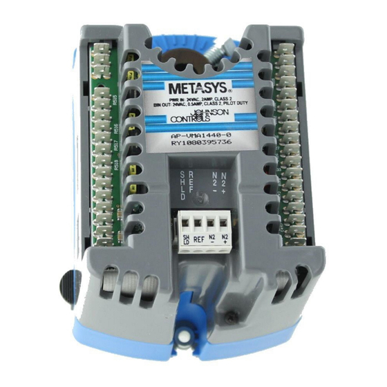
Mounting and Wiring Variable Air Volume Modular
Assembly (VMA) 1400 Series Controllers
Mounting and Wiring VMA1400 Series Controllers ...........................3
Introduction......................................................................................................... 3
Key Concepts...................................................................................................... 4
VMA Position and Orientation..........................................................................................4
Damper Actuator Direction to Close ................................................................................4
N2 Address Switches ......................................................................................................4
Wiring and Cabling Precautions ......................................................................................5
General Wiring Information..............................................................................................6
Power Source Wiring.......................................................................................................6
Phone Jack Polarization ................................................................................................10
Sensor Interfaces ..........................................................................................................11
Procedure Overview......................................................................................... 14
Detailed Procedures......................................................................................... 16
Preparing the VMA for Mounting....................................................................................16
Mounting the VMA1410/1420 ........................................................................................18
Mounting the VMA1430 .................................................................................................18
Wiring the VMA .............................................................................................................21
Connecting the N2 Bus..................................................................................................24
Reference Information ..................................................................................... 26
VMA Wiring List.............................................................................................................26
VMA Single Duct Application Wiring Diagram................................................................28
VMA Single Duct Supply/Exhaust Wiring Diagram ........................................................29
VMA Dual Duct Application Wiring Diagram ..................................................................30
© 2001 Johnson Controls, Inc.
Code No. LIT-6363125
T
B
ECHNICAL
ULLETIN
Technical Bulletin
Issue Date
11/01/01
www.johnsoncontrols.com
Advertisement
Table of Contents

Related Manuals for Johnson Controls VMA1400 Series


Summary of Contents for Johnson Controls VMA1400 Series
-
Page 1: Table Of Contents
11/01/01 ECHNICAL ULLETIN Mounting and Wiring Variable Air Volume Modular Assembly (VMA) 1400 Series Controllers Mounting and Wiring VMA1400 Series Controllers ......3 Introduction......................3 Key Concepts...................... 4 VMA Position and Orientation..................4 Damper Actuator Direction to Close ................4 N2 Address Switches ......................4 Wiring and Cabling Precautions ..................5... - Page 2 Mounting and Wiring VMA1400 Series Controllers Technical Bulletin VMA Internal Schematic Diagram..................32 Fabricating Your Own Interconnection Cable..............34 Troubleshooting ....................35 Troubleshooting VMA Room Temperature Drift .............35...
-
Page 3: Mounting And Wiring Vma1400 Series Controllers
Mounting and Wiring VMA1400 Series Controllers Technical Bulletin Mounting and Wiring VMA1400 Series Controllers Introduction The integrated VMA1410/1420, which includes a controller, actuator, and pressure sensor, mounts on the Variable Air Volume (VAV) terminal box. The VMA1430 mounts anywhere on the VAV box and is wired to a separate damper actuator. -
Page 4: Key Concepts
Mounting and Wiring VMA1400 Series Controllers Technical Bulletin Key Concepts VMA Position and Orientation Consider the following when positioning and orienting the VMA: • Mount the VMA on a vertical and flat surface where it functions best, such as the side of the VAV box. -
Page 5: Wiring And Cabling Precautions
Mounting and Wiring VMA1400 Series Controllers Technical Bulletin Wiring and Cabling Precautions WARNING: Possible Equipment Damage or Electrical Shock. To avoid damaging equipment or possible electrical shock, ensure that all power supplies to the system are disconnected prior to wiring. -
Page 6: General Wiring Information
Mounting and Wiring VMA1400 Series Controllers Technical Bulletin • Do not run N2 Bus, Zone Bus, Analog Input (AI), Binary Input (BI), Analog Output (AO), or Binary Output (BO) wiring in the same conduit as line voltage wiring (above 30 VAC), or with wiring that switches power to highly inductive loads such as contactors, coils, motors, or generators. - Page 7 Mounting and Wiring VMA1400 Series Controllers Technical Bulletin Table 1: Actuator VA Power Rating Actuator Type Power Rating VA-8020 Incremental 4 VA VA-8050 Incremental 6 VA VA-7150 Incremental 2.7 VA VA-7153 Incremental w/feedback 2.7 VA J Series Electric Zone Valve...
- Page 8 Mounting and Wiring VMA1400 Series Controllers Technical Bulletin < 88 ft of 14 AWG > 24 VAC 100 VA Example 1: All ten VMAs are at one end. 100 VA 24 VAC < 176 ft of 14 AWG > < 176 ft of 14 AWG >...
- Page 9 Mounting and Wiring VMA1400 Series Controllers Technical Bulletin The following tables indicate the relationship between cable length and power at the end of wires. Table 2: Maximum 24 VAC Secondary Cable Length for Given Power/Gauge (U.S. Measurements) Cable Size 8 Gauge...
-
Page 10: Phone Jack Polarization
Mounting and Wiring VMA1400 Series Controllers Technical Bulletin Phone Jack Polarization Figure 2 illustrates the polarization of the 6-pin and 8-pin phone jacks on the VMA or room sensor (TE-6700 or TMZ1600). Pin 1 is to the extreme left as you face the jack opening, tab notch down. -
Page 11: Sensor Interfaces
Mounting and Wiring VMA1400 Series Controllers Technical Bulletin Sensor Interfaces Figures 3, 4 and 5 show interfaces between room sensors and the VMA. For more information on the TE-6700 room sensor (including DIP switch settings), see the TE-6700 Series 2nd Generation Temperature Elements Installation Bulletin (LIT-216332). - Page 12 Mounting and Wiring VMA1400 Series Controllers Technical Bulletin (18) BI-1 (19) COM (20) BI-2 (21) COM (22) BI-3 (23) COM COM AI2 (24) +15 VDC (25) +15 VDC (26) AI-1 (27) COM (28) AI-2 (29) COM (30) AI-3 BI-1 ZB+ COM 15 VDC...
- Page 13 Mounting and Wiring VMA1400 Series Controllers Technical Bulletin TE-7000 (Europe Only) Terminal Blocks (TBs) (18) BI-1 (19) COM (20) BI-2 (21) COM (22) BI-3 (23) COM (24) +15 VDC (25) +15 VDC (26) AI-1 (27) COM (28) AI-2 (29) COM...
-
Page 14: Procedure Overview
Mounting and Wiring VMA1400 Series Controllers Technical Bulletin Procedure Overview Table 6: Mounting and Wiring VMA1400 Series Controllers To Do This Follow These Steps: Prepare the VMA for Mounting Check that you have the essential equipment and tools. For the VMA1410 and 1420, make certain that the damper shaft protrudes at least 44 mm (1-3/4 in.) from the VMA mounting surface. - Page 15 Mounting and Wiring VMA1400 Series Controllers Technical Bulletin To Do This (Cont.) Follow These Steps: Wire the VMA Disconnect all power to the VMA. Determine if spade lugs, removable 2- or 3-position screw terminals, or phone cable are to be used.
-
Page 16: Detailed Procedures
Mounting and Wiring VMA1400 Series Controllers Technical Bulletin Detailed Procedures Preparing the VMA for Mounting To prepare the VMA for mounting: Check that you have the following equipment: • • TE-6700, TE-7000 (Europe only), or TMZ1600 room sensor • room sensor cable or wire for connecting the room sensor to the VMA •... - Page 17 Mounting and Wiring VMA1400 Series Controllers Technical Bulletin Set the VMA specific N2 address using the N2 switches or via VBT or HVAC PRO programs. Use Addresses 1-253 only. Addresses 0 and 255 are reserved for software addressing, and Address 254 may not be used.
-
Page 18: Mounting The Vma1410/1420
Mounting and Wiring VMA1400 Series Controllers Technical Bulletin Mounting the VMA1410/1420 To mount the VMA1410/1420: Place the VMA in the desired mounting position on the damper shaft so the wiring terminals are easily accessible. To allow space for VMA movement during damper rotation, locate the shoulder washer at the center of the slot. -
Page 19: Setting The Damper Position (Vma1410, 1420, Or Vma1430 With External Actuator)
Mounting and Wiring VMA1400 Series Controllers Technical Bulletin Setting the Damper Position (VMA1410, 1420, or VMA1430 with External Actuator) To set the damper position: Locate the damper position, using the typical marking on the end of the damper shaft (Figure 8). Note the direction, Clockwise (CW) or Counterclockwise (CCW), required to close the damper. - Page 20 Mounting and Wiring VMA1400 Series Controllers Technical Bulletin Set Screw Collar rotated to its fully closed position. (CW to close in this example.) SHLD Damper shaft in Gear Release fully closed position. Lever ENDSTOP2 Figure 9: Positioning the End Stop (VMA1410 or VMA1420) Tighten the set screw to the shaft using a 8 mm (5/16 in.) wrench...
-
Page 21: Wiring The Vma
Mounting and Wiring VMA1400 Series Controllers Technical Bulletin Low Spot for Collecting Condensation STDMOUNT Figure 10: Standard Mounting Wiring the VMA Note: Refer to the project engineering drawings for wiring details. All field wiring, with the exception of the N2 Bus, must be kept in the same room with the controllers, to comply with UL smoke control requirements. - Page 22 Mounting and Wiring VMA1400 Series Controllers Technical Bulletin Note: AI-5 (velocity pressure) and the damper actuator are not listed in Tables 8-11 because they are internal points that do not require wiring. Table 8: Terminations for Cooling Only Single Duct...
- Page 23 Mounting and Wiring VMA1400 Series Controllers Technical Bulletin Table 10: Terminations for Single Duct Supply/Exhaust Cooling with Reheat Applications (VMA1420 and VMA1430) Name Description AI-1* Zone temperature AI-2* Zone setpoint AI-3 Exhaust air velocity pressure AI-4 Supply air temperature or sideloop...
-
Page 24: Connecting The N2 Bus
Mounting and Wiring VMA1400 Series Controllers Technical Bulletin Connecting the N2 Bus Note: A hardware connection between the VMA and the Network Control Module (NCM) or N30 is required if the VMA is to communicate with the Metasys Operator Workstation (OWS). - Page 25 Mounting and Wiring VMA1400 Series Controllers Technical Bulletin LEDVMA Figure 13: VMA LED Indicator Location Table 12: LED Indications If LED is... Interpretation On solid LED is running a 20 second power up self test. Allow it to continue. Blinking once per...
-
Page 26: Reference Information
Mounting and Wiring VMA1400 Series Controllers Technical Bulletin Reference Information VMA Wiring List Note: All field terminals are power limited when powered by a Class 2 transformer. Table 13: VMA Wiring List Point Description Range Input or Maximum Maximum Wire Size in... - Page 27 Mounting and Wiring VMA1400 Series Controllers Technical Bulletin Point Description Range Input or Maximum Maximum Wire Size in Cable (Cont.) Load Voltage Current or mm Length in Application Impedance (AWG) Meters (ft) AO-2* Proportional 0-10 VDC 1K-10M ohm 10 VDC 10 mA 1.5 mm...
-
Page 28: Vma Single Duct Application Wiring Diagram
Mounting and Wiring VMA1400 Series Controllers Technical Bulletin VMA Single Duct Application Wiring Diagram Figure 14: VMA Wiring Interface... -
Page 29: Vma Single Duct Supply/Exhaust Wiring Diagram
Mounting and Wiring VMA1400 Series Controllers Technical Bulletin VMA Single Duct Supply/Exhaust Wiring Diagram M9104-AGS-2N Return to (Actuator and Pressure Sensor) Exhaust Fan Connections to/from Main Controller (VMA) to Actuator/Sensor (M9104) (See detail in Figure 17.) Pressure Tubes Cold Air... -
Page 30: Vma Dual Duct Application Wiring Diagram
Mounting and Wiring VMA1400 Series Controllers Technical Bulletin VMA Dual Duct Application Wiring Diagram Figures 16 and 17 are wiring diagrams for dual duct applications. Connections to/from Main Controller (VMA) to M9104-AGS-2N Actuator/Sensor (M9104) (Actuator and Pressure Sensor) (See detail in Figure 17.) - Page 31 Mounting and Wiring VMA1400 Series Controllers Technical Bulletin Pressure Sensor BO 1 BCOM BO 2 AI 3 AI Com +15V (30) (31) (24) dualductap2 Figure 17: VMA Dual Duct or Single Duct Supply/Exhaust Wiring Diagram Detail: Connections to/from Main Controller to Actuator/Sensor...
-
Page 32: Vma Internal Schematic Diagram
Mounting and Wiring VMA1400 Series Controllers Technical Bulletin VMA Internal Schematic Diagram The small diagram in Figure 18 is a key diagram showing the different regions of the larger schematic diagram in Figure 19. 1. Isolated Power Supply 2. Earth Ground Connection 3. - Page 33 Mounting and Wiring VMA1400 Series Controllers Technical Bulletin = Optical or Earth ground is required Magnetic by NEC if primary is greater than 150 VAC. Isolation 24 VAC Primary 24 VAC Stepper Manual High Reset Temperature +15 V BCOM +5 V µ...
-
Page 34: Fabricating Your Own Interconnection Cable
Mounting and Wiring VMA1400 Series Controllers Technical Bulletin Fabricating Your Own Interconnection Cable Construct any fabricated interconnection cable so the same color wire on both ends of the cable aligns with Pin 1 in the plug. This provides a consistent field assembly of the cable. Figure 20 illustrates the interconnection cables for the TE-6700 and TMZ1600 sensors. -
Page 35: Troubleshooting
Mounting and Wiring VMA1400 Series Controllers Technical Bulletin Troubleshooting Troubleshooting VMA Room Temperature Drift Several job sites have reported that VMA zone temperature readings randomly drifted to extremely high values. Such readings cause the VAV box to drive to its full cooling level, resulting in occupant discomfort and unnecessary energy expenditure. - Page 36 Underwriters Laboratories, Inc. (UL) standards. This specifies dimensions to ensure that the phone plugs and jacks mate. Table 15 lists the AMP plugs that Johnson Controls has identified for use with the 8-position modular phone jack. Other manufacturers produce phone plugs that also connect properly to the phone jack.
- Page 37 Mounting and Wiring VMA1400 Series Controllers Technical Bulletin Table 15: AMP Modular Plug Assemblies (8-Position) AMP Part Cable Wire Specifications in mm (in.) Number 5-557315-3* Accepts: 0.6 mm (telephone cable) (24 or 26 AWG) solid wire Round Solid Insulation diameter: 0.74 to 0.99 (0.029 to 0.039) Maximum jacket diameter: 5.08 (0.200)
- Page 38 Mounting and Wiring VMA1400 Series Controllers Technical Bulletin Problem 4 Paint or other material on the phone plug prevents good connection between the temperature sensor (TE-6700 or TMZ1600) and the VMA. Contaminants block conductivity at either or both ends. Solution 4 Carefully inspect each plug and jack, cleaning away all contaminants before making a connection.