Table of Contents
Advertisement
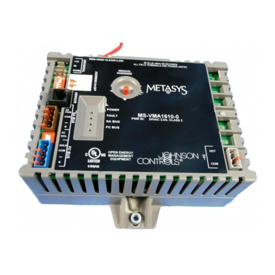
VMA1610 and VMA1620 Variable Air Volume Controllers
Installation Instructions
MS-VMA1610-xU, MS-VMA1620-xU
Applications
The VMA1610/1620 controllers are part of the Metasys®
family. VMA field controllers feature an integral 4 Nm
damper actuator and Differential Pressure Transducer.
VMA controllers run pre-engineered and
user-programmed applications required to monitor and
operate a wide variety of VAV boxes.
The VMA controllers operate on an RS-485 BACnet®
Master-Slave/Token-Passing (MS/TP) Bus as BACnet
Application Specific Controllers (B-ASCs) and integrate
into the web-based Metasys system.
Note: Only -xU models of these controllers are available.
These models are for smoke control applications
only. If your application is not for a UL 864 UUKL
10th Edition smoke control application, please
review the product selection before installation.
Important: In Metasys® system smoke control
applications, use only the VMA1610 and
VMA1620 models that are UL 864
UUKL/UUKLC 10th Edition Smoke Control
Listed. For Metasys system smoke control
applications, you must refer to the Metasys
System UL 864 UUKL Tenth Edition Smoke
Control System Technical Bulletin
(LIT-12012487) for detailed requirements
and procedures for installing,
commissioning, and operating UL 864
UUKL/UUKLC Listed Metasys system
devices. The UL 864 UUKL/UUKLC listing
for Smoke Control Equipment is voided if
(1) you do not use the required software
tools at the required versions; or (2) you do
not meet the requirements or do not follow
the procedures as documented in the
Metasys System UL 864 UUKL Tenth
Edition Smoke Control System Technical
Bulletin (LIT-12012487).
VMA1610 and VMA1620 Variable Air Volume Controllers Installation Instructions
Part No. 24-10143-20, Rev. U
Refer to the
QuickLIT website
North American Emissions
Compliance
United States
This equipment has been tested and found to comply
with the limits for a Class A digital device pursuant to
Part 15 of the FCC Rules. These limits are designed to
provide reasonable protection against harmful
interference when this equipment is operated in a
commercial environment. This equipment generates,
uses, and can radiate radio frequency energy and, if not
installed and used in accordance with the instruction
manual, may cause harmful interference to radio
communications. Operation of this equipment in a
residential area may cause harmful interference, in which
case the users will be required to correct the interference
at their own expense.
Canada
This Class (A) digital apparatus meets all the
requirements of the Canadian Interference-Causing
Equipment Regulations.
Cet appareil numérique de la Classe (A) respecte toutes
les exigences du Règlement sur le matériel brouilleur
du Canada.
Installation
Observe these guidelines when installing a VMA16
controller:
•
Transport the controller in the original container to
minimize vibration and shock damage to the VMA
controller.
•
Do not drop the controller or subject it to physical
shock.
Parts Included
•
one VMA16 controller with removable bus and power
terminal blocks
•
one installation instructions sheet
Issued November 2017
for the most up-to-date version of this document.
1
Advertisement
Table of Contents

Related Manuals for Johnson Controls Metasys VMA1610


Summary of Contents for Johnson Controls Metasys VMA1610
- Page 1 VMA1610 and VMA1620 Variable Air Volume Controllers Installation Instructions MS-VMA1610-xU, MS-VMA1620-xU Part No. 24-10143-20, Rev. U Issued November 2017 Refer to the QuickLIT website for the most up-to-date version of this document. Applications North American Emissions The VMA1610/1620 controllers are part of the Metasys® family.
-
Page 2: Materials And Special Tools Needed
To mount the VMA16 controller: Materials and Special Tools Needed Place the controller in the proper mounting position on the damper shaft so that the wiring connections • one screw or other type of fastener appropriate for are easily accessible. Make sure the controller base the mounting surface is parallel to the VAV box (perpendicular to the •... - Page 3 in.) 12-point socket. Tighten to 11 to 15 N·m (100 to 130 lb·in). Loop the pneumatic tubing to include a trap for condensation. Attach the tubing from the VMA Risk of Property Damage. Rotate the damper to controller to the VAV box pickup. The HIGH (red) the full-open position before starting the air handler.
- Page 4 Figure 2: VMA16 Controller Physical Features and Wiring Terminations VMA1610 and VMA1620 Variable Air Volume Controllers Installation Instructions...
- Page 5 Wiring FC Bus Terminal Block The FC Bus terminal block is a blue, removable, 4-terminal plug that fits into a board-mounted jack. Risk of Electric Shock. Disconnect the power supply before making electrical connections to avoid electric Wire the removable FC Bus terminal block plugs on the shock.
-
Page 6: Sensor Port
Figure 4: SA Bus Terminal Block Wiring The supply power wire colors may be different on transformers from other manufacturers. Refer to the transformer manufacturer’s instructions and the project installation drawings for wiring details. Important: Connect 24 VAC supply power to the VMA and all other network devices so that transformer phasing is uniform across the network devices. -
Page 7: Vma Terminal Functions, Ratings, Requirements, And Wiring Guidelines
Table Internal 12 V, 15k ohm pull up Qualified Sensors: 0–2k potentiometer, RTD (1k Nickel [Johnson Controls sensor], 1k Platinum, and A99B Silicon Temperature Sensor) Negative Temperature Coefficient (NTC) Sensor 10K Type L (10K JCI Type II is equivalent to Type L) or 2.252K Type II... - Page 8 Table 1: I/O Terminal Blocks, Functions, Ratings, Requirements, and Cables Terminal Block Terminal Function, Ratings, and Requirements To Determine Wire Size and Label Labels Maximum Cable Length BINARY OUTn Binary Output - 24 VAC Triac (Internal Power) See Guideline C in Table (Outputs) Sources internal 24 VAC power (24~ HOT)
-
Page 9: Termination Details
Use stranded copper wire. Use twisted wire cable. Termination Details A set of Johnson Controls® termination diagrams provides details for wiring inputs and outputs to the controllers. See the figures in this section for the applicable termination diagrams. Table 3: Termination Details... - Page 10 Table 3: Termination Details Type of Field Device Type of Termination Diagrams Input/Output Voltage Input (Self-Powered) Dry Contact 0–10 VDC Output to CO or AO Actuator (External Source) 0–10 VDC Output to CO or AO Actuator (Internal Source) Analog Output (Voltage) CO or AO 24 VAC Triac Output CO or AO...
- Page 11 Table 3: Termination Details Type of Field Device Type of Termination Diagrams Input/Output Incremental Control to CO or AO Actuator (Switch Low, Externally Sourced) 24 VAC Binary Output (Switch Low, Internal Source) Incremental Control to Actuator (Switch Low, Internal Source) Network Stat with Phone SA Bus Jack (Fixed Address =...
-
Page 12: Maximum Cable Length Versus Load Current
Table 3: Termination Details Type of Field Device Type of Termination Diagrams Input/Output Network Stat with SA Bus Terminals Addressable Network Stat with SA Bus Terminals (Fixed Address = 199) Maximum Cable Length versus Load Current Figure 7 to estimate the maximum cable length relative to the wire size and the load current (in mA) when wiring inputs and outputs. -
Page 13: Fc And Sa Bus And Supply Power Wiring Guidelines
Figure 7: Maximum Wire Length by Current and Wire Size In addition to the guidelines in Table 4, observe these FC and SA Bus and Supply guidelines when wiring the SA/FC Buses and supply Power Wiring Guidelines power: Table 4 provides information about terminal block •... -
Page 14: Setup And Adjustments
Table 4: Communication Bus and Supply Power Terminal Blocks, Functions, Ratings, Requirements, and Cables Terminal Terminal Labels Function, Electrical Ratings/Requirements Recommended Cable Type Block/Port Label SENSOR RJ-12 6-Position Modular Connector provides: 24 AWG 3-pair CAT 3 Cable SENSOR SA Bus Communications <30.5 m (100 ft) (SA Bus Port) SA Bus Signal Reference and 15 VDC Common... -
Page 15: Setting The Eol Switch
Table 5 describes the valid FC Bus and SA Bus devices is not a terminating device on the bus, set the EOL addresses for Johnson Controls® MS/TP communications switch to off. bus applications. Table 5: SA/FC Bus Device Address Descriptions... -
Page 16: Repair Information
Descriptions of LED If the VMA controller fails to operate within its Label Color State States specifications, contact the Johnson Controls® Repair Center in Louisville, Kentucky, at 1-502-671-7312. The FC BUS Green Blink - 2 Blink - 2 Hz = Data... -
Page 17: Technical Specifications
Technical Specifications Table 8: VMA16 Controllers Product Code Numbers MS-VMA1610-0U: 1 UI VMA (Cooling Only) MS-VMA1610-1U: 1 UI VMA (Cooling Only) MS-VMA1620-0U: 1 UI, 3 BO, 2 CO VMA (Cooling with Reheat and Fan Control) Note: MS-VMA1620-1U: 1 UI, 3 BO, 2 CO VMA (Cooling with Reheat and Fan Control) Only -xU models of these controllers are available. - Page 18 The performance specifications are nominal and conform to acceptable industry standard. For application at conditions beyond these specifications, consult the local Johnson Controls office. Johnson Controls shall not be liable for damages resulting from misapplication or misuse of its products.
- Page 19 Building Technologies & Solutions 507 E. Michigan Street, Milwaukee, WI 53202 Metasys® and Johnson Controls® are registered trademarks of Johnson Controls. All other marks herein are the marks of their respective owners.© 2017 Johnson Controls Published in U.S.A. www.johnsoncontrols.com VMA1610 and VMA1620 Variable Air Volume Controllers Installation Instructions...