Johnson Controls VMA1615 Installation Manual
Vav controllers
Hide thumbs
Also See for VMA1615:
- Installation instructions manual (24 pages) ,
- Installation instructions manual (22 pages)
Table of Contents
Advertisement
Applications
The VMA1615/1626/1628/1630 programmable digital
controllers are designed for Variable Air Volume
(VAV) applications that communicate through the
BACnet
MS/TP or N2 protocol. These Variable
®
Air Volume Modular Assembly (VMA) controllers
feature combinations of an integral digital pressure
sensor (DPT), a damper actuator, and a 32-bit
microprocessor. The VMA1626 has an actuator
but does not contain a DPT. The VMA1628 model
has a DPT but does not contain an actuator. The
controllers' small package size facilitates quick
field installation and efficient use of space without
compromising high-tech control performance. These
VMA controllers connect easily to the wired and
wireless network sensors for zone and discharge air
temperature sensing.
Switchable Communications
protocols
The Metasys
system Field Equipment Controller
®
(FEC) family controllers and network sensors
communicate using the standard BACnet
based on the ANSI/ASHRAE 135-2008. The BACnet
protocol is a standard for ANSI, ASHRAE, and the
International Standards Organization (ISO) for
building controls.
VMA16, VMA18 controllers are BTL-listed as BACnet
Application Specific Controllers (B-ASCs).
The Controller Configuration Tool (CCT) can be used
to switch the Field Bus communications protocol in
supported FEC, FAC, and VMA controllers to be either
the standard BACnet MS/TP or the N2 protocol. All
new controllers use either BACnet MS/TP as the
default communications protocol, or BACnet/IP.
Switchable communications protocols in the MS/
TP models provide a cost-effective upgrade and
modernization path for customers with existing N2
controllers.
The N2-capable FEC Family Controllers can be used
as functional replacements for legacy N2 controllers.
The N2-capable FEC Family Controllers:
• have the input and output (I/O) quantities and
characteristics of the FEC Family Controllers
VMA1615/1626/1628/1630 VAV Controllers
• must be programmed with CCT, which has similar,
but not identical programming capabilities as
HVACPro, GX9100, GPL, and other legacy tools
• support SA Bus devices
• support WRZ wireless sensors from the controller
using the WRZ-7860 receiver (most models)
• are available in Buy American versions (most
models)
The N2-capable FEC family controllers:
• do not support Zone Bus (for example, TMZ
sensors and M100 actuators) or XT-Bus (System
91) devices (for example, XT, XTM, and XP
modules)
• do not support a wireless connection to the N2
bus
• do not support NxE passthrough
North American Emissions
Compliance
protocol,
®
United States
This equipment has been tested and found to comply with the
limits for a Class A digital device pursuant to Part 15 of the FCC
Rules. These limits are designed to provide reasonable protection
against harmful interference when this equipment is operated
in a commercial environment. This equipment generates, uses,
and can radiate radio frequency energy and, if not installed
and used in accordance with the instruction manual, may cause
harmful interference to radio communications. Operation
of this equipment in a residential area may cause harmful
interference, in which case the users will be required to correct
the interference at their own expense.
Canada
This Class (A) digital apparatus meets all the requirements of the
Canadian Interference-Causing Equipment Regulations.
Cet appareil numérique de la Classe (A) respecte toutes les
exigences du Règlement sur le matériel brouilleur du Canada.
Installation Guide
Part No. 24-10143-217 Rev. K
2019-10-18
*2410143217K*
(barcode for factory use only)
MS-VMA1615,MS-VMA1626,MS-VMA
1628,MS-VMA1630
Advertisement
Table of Contents

Related Manuals for Johnson Controls VMA1615


Summary of Contents for Johnson Controls VMA1615
- Page 1 2019-10-18 Applications • must be programmed with CCT, which has similar, but not identical programming capabilities as The VMA1615/1626/1628/1630 programmable digital HVACPro, GX9100, GPL, and other legacy tools controllers are designed for Variable Air Volume • support SA Bus devices...
-
Page 2: Installation
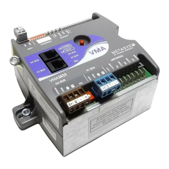
VMA • Pliers to open and close the damper Parts included • Required length of 3.97 mm (5/32 in.) ID • One VMA1615/1626/1628/1630 controller with pneumatic tubing and barbed fittings removable SA bus and power terminal blocks Physical features •... - Page 3 Figure 1: VMA1615/1626/1628/1630 Controller wiring terminations and physical features (VMA1630-1 Model shown) Table 1: VMA1615/1626/1628/1630 Feature Callout Table 1: VMA1615/1626/1628/1630 Feature Callout Numbers and Descriptions Numbers and Descriptions Physical Features: Description and References Physical Features: Description and References Universal Input: Voltage Analog Input (0–10 VDC)
- Page 4 • Avoid mounting the controller on surfaces with excessive vibration. 4. Locate the damper position using the typical • When using the VMA1615/1626/1628/1630 to marking on the end of the damper shaft as replace a VMA1610 or VMA1620 controller, plug shown in the following figure.
- Page 5 8 mm (5/16 in.) wrench or 10 mm (3/8 in.) 12-point socket. Tighten to 10.5 to 11.5 N·m (95 to 105 lb·in). VMA1615/1626/1628/1630 VAV Controllers Installation Guide...
-
Page 6: Vma Terminals And Bus Ports
Figure 4. See Table for more information. VMA terminals and bus ports See for input and output terminal and bus port locations on the controllers. Observe the following guidelines when wiring a VMA controller. VMA1615/1626/1628/1630 VAV Controllers Installation Guide... -
Page 7: Modular Ports
Important: Exercise caution while rewiring VMA1615/1626/1628/1630 Controllers the power plug when replacing a VMA1610 or VMA1620 controller with a VMA1615 or VMA1630 controller. The supply power terminal on a new VMA is a two-position terminal block (Figure 6). A VMA1610 or VMA1620 controller uses a three-position terminal block, and the center position is not used. -
Page 8: Terminal Wiring Guidelines, Functions, Ratings, And Requirements
3. Wire the FC Bus in a daisy chain. 4. Ensure that the device address DIP switches are set to the appropriate device address (See ). Also, activate the EOL switch if necessary. 5. Connect the controller to 24 VAC, Class 2 power. VMA1615/1626/1628/1630 VAV Controllers Installation Guide... -
Page 9: Input And Output Wiring Guidelines Tables
Sensor) UNIVERSAL Negative Temperature Coefficient (NTC) (Inputs) Sensor 10K Type L (10K Johnson Controls Type II is equivalent to Type L) or 2.252K Type II Binary Input - Dry Contact Maintained Mode See Guideline A in Table 3. 1 second minimum pulse width... -
Page 10: Maximum Cable Length Versus Load Current
Use twisted wire cable. Maximum cable length versus load current Use Figure 8 to estimate the maximum cable length relative to the wire size and the load current (in mA) when wiring inputs and outputs. VMA1615/1626/1628/1630 VAV Controllers Installation Guide... -
Page 11: Communications Bus And Supply Power Wiring Guidelines
NS Series Sensors 24 AWG 3-pair CAT 3 Cable <30.5m Wireless ZigBee WRZ-78xx Series One- SA BUS SA BUS to-One Wireless Receiver (100 ft) Wireless Bluetooth Commissioning Converter (BTCVT) DIS1710 Local Controller Display VAV Balancing Tool VMA1615/1626/1628/1630 VAV Controllers Installation Guide... - Page 12 The SA Bus and FC Bus wiring recommendations in this table are for MS/TP Bus communications at 38.4k baud. For more information, refer to the Metasys IP Networks for BACnet/IP Controllers Configuration Guide (LIT-12012458).andMS/TP Communications Bus Technical Bulletin (LIT-12011034). VMA1615/1626/1628/1630 VAV Controllers Installation Guide...
-
Page 13: Termination Diagrams
Termination diagrams A set of Johnson Controls termination diagrams provides details for wiring inputs and outputs to the controllers. See the figures in this section for the applicable termination diagrams. Table 5: Termination details Type of Input/ Type of field device... - Page 14 Note: Applies to CO4 and CO5. Incremental Control to Actuator (Switch Low, External Source) Note: Applies to CO4 and CO5. Analog Output (Voltage) Incremental Control to Actuator (Switch Low, Internally Sourced) Note: Applies to BO3, BO1, and BO2. VMA1615/1626/1628/1630 VAV Controllers Installation Guide...
-
Page 15: Setup And Adjustments
128, 64, 32, 16, 8, 4, 2, and 1. Switches 64 Metasys field controllers are master devices on through 1 are device address switches. Switch 128 BACnet MSTP (SA or FC) Buses. Before operating ® VMA1615/1626/1628/1630 VAV Controllers Installation Guide... - Page 16 Note: Do not connect a wirelessly enabled ON and the remaining address switches (Switch 128 ON) field controller to a wired FC Bus. OFF, rendering the controllers wired subordinate devices, which do not operate on Metasys field buses. VMA1615/1626/1628/1630 VAV Controllers Installation Guide...
-
Page 17: Setting The Eol Switch
LED light on the face of the controller is illuminated. Using an SA bus connection, download the firmware and controller application file. The download process asks to confirm switching the communication protocol to N2. Click OK. VMA1615/1626/1628/1630 VAV Controllers Installation Guide... -
Page 18: Commissioning Field Controllers
2. Use an ohm-meter to measure between ~24 VAC HOT and COM; there should be no short 3. SA bus device is not wired with the same circuit. polarity as the controller. VMA1615/1626/1628/1630 VAV Controllers Installation Guide... -
Page 19: Led Status And States
Off Steady = No data transmission (N/A - auto baud SA BUS Green Blink - 2 Hz not supported) On Steady = Communication lost; waiting to join communication ring On Steady = EOL is active Amber Off Steady = EOL is not active VMA1615/1626/1628/1630 VAV Controllers Installation Guide... - Page 20 VMA Actuator Assembly Gearbox Replacement Kit AS-CBLTSTAT-0 Cable adapter for connection to 8-pin TE-6700 Series sensors Replacement Barbed Fitting for use on VMA1615, VMA1630, and VMA1832 for Connecting F-1000-325 Tubing, Bulk Pack of 10 Flexible Tubing Extension with Barbed Fitting for VMA1615, VMA1630, and VMA1832, 35.56 F-1000-326 cm (14 in.) Length, Bulk Pack of 20...
-
Page 21: Technical Specifications
Technical specifications Table 10: VMA1615/1626/1628/1630 Controllers MS-VMA1615-x: 32-bit, Integrated VAV Controller/Actuator/Pressure Sensor - DPT, 3 UI and 2 BO, 24VAC, FC and SA Bus MS-VMA1626-x: 32-bit, Integrated VAV Controller/Actuator (No Pressure Sensor - DPT); 3 UI, 3 BO, and 2 CO; 24VAC; FC and SA Bus Product Code Numbers MS-VMA1628-x: 32-bit, Integrated VAV Controller/(No Actuator) Pressure Sensor - DPT;... -
Page 22: Product Warranty
DISTRICT WUXI JIANGSU PROVINCE 214028 CHINA For more contact information, refer to www.johnsoncontrols.com/locations. © 2019 Johnson Controls. All rights reserved. All specifications and other information shown were current as of document revision and are subject to change without notice. www.johnsoncontrols.com...