Table of Contents
Advertisement
Series Overview and Engineering Guidelines
VMA1400 Series Overview and Engineering Guidelines ...................2
Introduction......................................................................................................... 2
Key Concepts...................................................................................................... 3
VMA1400 Series Models................................................................................................... 3
VAV System ...................................................................................................................... 6
Definition of Terms ............................................................................................................ 9
Room Sensor Placement ................................................................................................ 10
Pressure Independence .................................................................................................. 10
VMA Airflow Rate ............................................................................................................ 10
Power Source.................................................................................................................. 11
N2 Bus Rules .................................................................................................................. 12
Inputs and Outputs.......................................................................................................... 13
Zone Bus......................................................................................................................... 14
CablePRO ....................................................................................................................... 15
CVTPRO ......................................................................................................................... 15
Related Documentation................................................................................................... 16
Application Examples...................................................................................................... 17
Reference Information..................................................................................................... 26
Specifications .................................................................................................................. 27
Detailed Procedures......................................................................................... 32
Determining VAV Box Requirements .............................................................................. 32
Establishing the Room Schedule .................................................................................... 32
Developing the Bill of Material and Placing Orders ......................................................... 33
Configuring the VMA ....................................................................................................... 35
© 2006 Johnson Controls, Inc.
Code No. LIT-6363120
Technical Bulletin
Issue Date
February 28, 2006
www.johnsoncontrols.com
Advertisement
Table of Contents

Related Manuals for Johnson Controls VMA 1410


Summary of Contents for Johnson Controls VMA 1410
-
Page 1: Table Of Contents
Specifications ........................27 Detailed Procedures..................32 Determining VAV Box Requirements ................32 Establishing the Room Schedule ..................32 Developing the Bill of Material and Placing Orders ............33 Configuring the VMA ....................... 35 © 2006 Johnson Controls, Inc. www.johnsoncontrols.com Code No. LIT-6363120... -
Page 2: Vma1400 Series Overview And Engineering Guidelines
VMA1400 Series Overview and Engineering Guidelines Technical Bulletin VMA1400 Series Overview and Engineering Guidelines Introduction The Variable Air Volume Modular Assembly (VMA) 1400 Series is a configurable, integrated module that includes a Variable Air Volume (VAV) controller, differential pressure sensor, and, with the exception of the VMA1430, an actuator. -
Page 3: Key Concepts
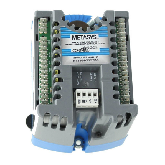
VMA1400 Series Overview and Engineering Guidelines Technical Bulletin Key Concepts VMA1400 Series Models VMA1430 VMA1410 VMA1420 VMA14xx Figure 1: VMA1400 Series Models The VMA is a configurable, integrated module that includes a VAV controller and differential pressure sensor. The VMA1400 Series includes three models: VMA1410 (cooling only, includes actuator) VMA1420 (cooling with reheat, includes actuator) - Page 4 VMA1400 Series Overview and Engineering Guidelines Technical Bulletin Table 1: VMA1400 Series Comparison Checklist VMA Features 1410 1420 1430 Comments Applications Pattern Recognition Adaptive Eliminates manual tuning and Control (PRAC) on Zone Proportional seasonal re-tuning plus Integral plus Derivative (PID) Temperature Loops Adaptive Flow Control Loops Eliminates manual tuning,...
- Page 5 VMA1400 Series Overview and Engineering Guidelines Technical Bulletin VMA Features (Cont.) 1410 1420 1430 Comments Commissioning Balancing Tool with Automatic HVAC PRO software (single duct Pickup Gain Calculation only) or VMA Balancing Tool (VBT) software on Zone Bus Hardware 24 Volts Alternating Current (VAC) Eliminates 24 to 24 VAC Isolation Built-in transformer and polarity concerns...
-
Page 6: Vav System
VMA1400 Series Overview and Engineering Guidelines Technical Bulletin VAV System Theory of Operation A VAV air handling system typically consists of a single air handling unit and multiple terminal units. Terminal units typically consist of a damper and flow sensing probe installed in an enclosure. VAV terminal units are also called VAV boxes. - Page 7 VMA1400 Series Overview and Engineering Guidelines Technical Bulletin The VMA quickly adjusts the damper position to new conditions, and minimizes position hunting and motor runtime. The fast response stepper actuator on the VMA1410 and 1420 drives the damper from full open to full closed in 30 seconds. This significantly reduces the time to commission a VAV box.
- Page 8 VMA1400 Series Overview and Engineering Guidelines Technical Bulletin Ethernet LAN Network Network Control Control Unit Module N 30 (NCU) (NCM) VMA1400 Operator Workstation DX9100 DX9100 VMA1400 TC9102 VMA1400 Unitary Controller (UNT) Zone CablePRO Converter Room Laptop Sensor Room Sensor ™ Palm Compatible Handheld Device...
-
Page 9: Definition Of Terms
VMA1400 Series Overview and Engineering Guidelines Technical Bulletin Definition of Terms Autocalibration To correct for pressure sensor drifts over time, the VMA has an Autocalibration mode that automatically compensates for temperature and humidity effects. N2 Switches Single-pole, single-throw switches used to set the N2 address of a controller. -
Page 10: Room Sensor Placement
VMA1400 Series Overview and Engineering Guidelines Technical Bulletin Room Sensor Placement When considering room sensor placement for each zone: • Verify that the room sensor is the correct one for the application. • Review architectural requirements such as furniture height and location, aesthetics, and type of mounting. -
Page 11: Power Source
VMA1400 Series Overview and Engineering Guidelines Technical Bulletin The DPT provides maintenance-free performance within the control range of 1 to 18 m/s (200 to 3500 feet per minute [fpm]) when used as recommended. Pressure independent VAV terminal boxes use an airflow pickup device, which amplifies the airflow velocity pressure between 1.5 to 3 times (varies by manufacturer). -
Page 12: N2 Bus Rules
VMA1400 Series Overview and Engineering Guidelines Technical Bulletin N2 Bus Rules The N2 Bus is the interface between a supervisory controller (Metasys Network Control Module [NCM] or N30) and all application specific controllers in a Metasys Network. The VMA is self-terminating in that there are no End-of-Line (EOL) jumpers to set. -
Page 13: Inputs And Outputs
VMA1400 Series Overview and Engineering Guidelines Technical Bulletin Inputs and Outputs For specific input/output range, cable length, wire size issues, refer to the Mounting and Wiring Variable Air Volume Modular Assembly (VMA) 1400 Series Controllers Technical Bulletin (LIT-6363125). Note: All terminals are spade lug type except the N2 terminals, which are removable screw terminals. -
Page 14: Zone Bus
VMA1400 Series Overview and Engineering Guidelines Technical Bulletin Zone Bus The Zone Bus is a 2-wire communications bus that allows a computer to commission and balance the VMA’s database. The computer must have the proper software and must connect through the CablePRO (AS-CBLPRO or IU-9100 in Europe) or CVTPRO (AS- CVTPROx00-x) converter and the room sensor. -
Page 15: Cablepro
VMA1400 Series Overview and Engineering Guidelines Technical Bulletin CablePRO CablePRO (AS-CBLPRO) is an interface device that is used between a computer or Palm™ compatible handheld device and the VMA. Use CablePRO for box balancing or commissioning via the Zone Bus communication port on the room sensor. -
Page 16: Related Documentation
VMA1400 Series Overview and Engineering Guidelines Technical Bulletin Related Documentation Table 5 lists related VMA documentation. Table 5: Related Documentation For Information on This Use This Document: Sales and Marketing Information Variable Air Volume Modular Assembly (VMA) 1400 Series Product Bulletin (LIT-635058) Downloading and HVAC PRO User’s Guide... -
Page 17: Application Examples
VMA1400 Series Overview and Engineering Guidelines Technical Bulletin Application Examples Note: The examples in this document do not reflect all of the possible questions and answers. These examples provide a basic overview of wiring locations you might expect to see. They do not define all available applications. - Page 18 VMA1400 Series Overview and Engineering Guidelines Technical Bulletin Figure 4: Single Duct Fan-Powered Box Example 1...
- Page 19 VMA1400 Series Overview and Engineering Guidelines Technical Bulletin Single Duct Application Example 2 Table 8 illustrates the selections made through HVAC PRO software for this example. Table 8: Example 2 Questions HVAC PRO Software Questions Configuration Selections Control Strategy Pressure Independent, Single Duct Supply Damper Actuator (DA1) Floating/3-wire Fan Type (R)
- Page 20 VMA1400 Series Overview and Engineering Guidelines Technical Bulletin Figure 6: Single Duct Fan-Powered Box Example 2...
- Page 21 VMA1400 Series Overview and Engineering Guidelines Technical Bulletin Single Duct Supply/Exhaust Application Example Table 10 illustrates the selections made through HVAC PRO software for this example. Table 10: Example Questions HVAC PRO Software Questions Configuration Selections Control Strategy Pressure Independent, Supply/Exhaust Supply Actuator VMA Integrated Actuator Fan Type...
- Page 22 VMA1400 Series Overview and Engineering Guidelines Technical Bulletin Single Duct Supply/Exhaust with BO Solenoid Application Example Table 12 illustrates the selections made through HVAC PRO for Windows operating system for this example. Note: This example only applies to HVAC PRO 8.05 or later. Table 12: Example Questions HVAC PRO Software Questions Configuration Selections...
- Page 23 VMA1400 Series Overview and Engineering Guidelines Technical Bulletin Figure 9: Single Duct Supply/Exhaust with BO Solenoid Example...
- Page 24 VMA1400 Series Overview and Engineering Guidelines Technical Bulletin Dual Duct Application Example Table 14 illustrates the selections made through HVAC PRO software for this example. Note: This example only applies to HVAC PRO 8.0 or later. Table 14: Example Questions HVAC PRO Software Questions Configuration Selections Control Strategy...
- Page 25 VMA1400 Series Overview and Engineering Guidelines Technical Bulletin Figure 11: Dual Duct Example...
-
Page 26: Reference Information
VMA1400 Series Overview and Engineering Guidelines Technical Bulletin Reference Information VMA Parts List Table 16: Available VMA Models Inputs/Outputs Points Rating VMA1410 VMA1420 VMA1430 (Cooling (Cooling Only) w/Reheat) Analog Inputs Zone Temperature AI-1 1 K Ni, Si, or Pt or 2.25 K NTC Zone Setpoint AI-2... -
Page 27: Specifications
VMA1400 Series Overview and Engineering Guidelines Technical Bulletin Specifications Table 17: Specifications Feature Specification Product Name Variable Air Volume Modular Assembly (VMA) Product Code Cooling Only Cooling with Reheat and/or Models without Number Models: Fan Powered Models: Actuators: Single Unit AP-VMA1410-0 AP-VMA1420-0 AP-VMA1430-0... - Page 28 VMA1400 Series Overview and Engineering Guidelines Technical Bulletin Feature (Cont.) Specification Standards CSA C22.2 No. 205 Compliance UL916, UL864 (UUKL), UL94-5VB FCC CFR47 Part 15, Subpart B, Class A and B Verified C-tick Australia, AS/NZS 4251.1 CE EMC Directive 89/336/EEC, (EN 50081-1, CISPR 11, Class B, EN 50082-2) IEEE 472, IEEE 518, IEEE 587 Category A/B Accessories AP-TBK1002-0* Removable 2-position screw terminal kit (100 pcs)
- Page 29 VMA1400 Series Overview and Engineering Guidelines Technical Bulletin Table 18: Additional Detailed VMA Specifications Feature Specification Power Input Voltage Range 20 to 30 VAC; 50 or 60 Hz Input Current 0.5 Ampere without Relays or Valves Transient Protection Isolated from AI, BI, AO, ZBus, +15 VDC and N2 Bus; Common and Normal Mode Capacitor N2 Bus Communications Bus Type and Voltage...
- Page 30 VMA1400 Series Overview and Engineering Guidelines Technical Bulletin Feature (Cont.) Specification Temperature Inputs Range NTC: -20 to 105°C (-4 to 221°F) Nickel: -45 to 121°C (-50 to 250°F) Silicon: -40 to 102°C (-40 to 216°F) Platinum: -50 to 200°C (-58 to 392°F) Setpoint: 18 to 28°C (65 to 85°F) Resolution (15 bit) NTC:...
- Page 31 VMA1400 Series Overview and Engineering Guidelines Technical Bulletin Feature (Cont.) Specification Analog Outputs (AP-VMA1420 and VMA1430) Voltage Range 0 to 10 VDC Load Current 0 to 10 mA Voltage Resolution (12-bit) 0.002 VDC Non-Repeatability (estimate) +0.02 VDC maximum Voltage Tolerance +0.20 VDC maximum Thermal Tolerance +0.018% per degree C (+0.032% per degree F) maximum...
-
Page 32: Detailed Procedures
VMA1400 Series Overview and Engineering Guidelines Technical Bulletin Detailed Procedures Determining VAV Box Requirements To determine VAV box requirements: 1. Select the VMA based on control sequence, Input/Output (I/O), side loops, and flow measurement accuracy requirements. 2. Establish sensor placement in zones. 3. -
Page 33: Developing The Bill Of Material And Placing Orders
• differential pressure sensors (dual duct only) • valves • valve actuators • box fan speed controllers - for information about the Johnson Controls® S66 Series Electronic Fan Speed Control, refer to the S66 Series Electronic Fan Speed Control Product/Technical Bulletin (LIT-121605). • cables... - Page 34 If VMAs are installed on an N2 Bus connected to an NCM, the NCM requires a minimum of 4 MB of memory. 2. Coordinate parts ordering and delivery, including: • placing orders through Johnson Controls Customer Service • determining shipping destinations • coordinating VMA manufacturing and delivery issues •...
-
Page 35: Configuring The Vma
VMA1400 Series Overview and Engineering Guidelines Technical Bulletin Configuring the VMA To configure the VMA: 1. Refer to the appropriate room schedule for room specifications. 2. Assign the N2 address for each device. 3. Using the HVAC PRO tool (EURO PRO tool in Europe), select control sequences.