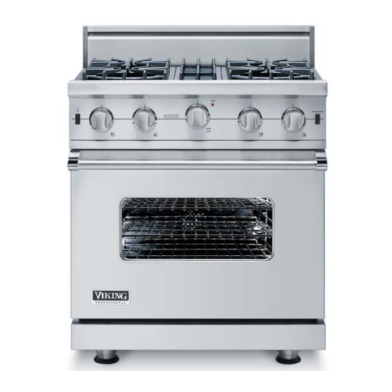
Viking VGIC530 Service Manual
30 & 36 inch gas range
Hide thumbs
Also See for VGIC530:
- Manual (48 pages) ,
- Use & care manual (22 pages) ,
- Installation manual (12 pages)
Table of Contents
Advertisement
Service
Manual
This manual is to be used by qualifi ed appliance technicians only. Viking
does not assume any responsibility for property damage or personal
injury for improper service procedures done by an unqualifi ed person.
30 & 36 Inch
Gas Range
Preferred Service
This Base Manual covers general and
specifi c information including, but not
limited to the following models:
September 2010
®
VGIC530
VGIC536
SMC-0018
Advertisement
Table of Contents

Related Manuals for Viking VGIC530


Summary of Contents for Viking VGIC530
- Page 1 Service Preferred Service Manual This manual is to be used by qualifi ed appliance technicians only. Viking does not assume any responsibility for property damage or personal injury for improper service procedures done by an unqualifi ed person. 30 & 36 Inch This Base Manual covers general and specifi...
-
Page 2: Table Of Contents
Inner Door Glass Removal ........22 Bake Burner Igniter Removal ......... 23 Bake Burner Removal ..........23 Bake Burner Orifi ce Removal ........ 23 Broil Burner Igniter Removal ........24 Temperature Sensor (RTD) Removal..... 24 Convection Fan Assembly Removal ...... 24 ©2010 Viking Preferred Service... -
Page 3: Important Information
All safety messages will be preceded by the safety alert symbol and the word “DANGER”, “WARNING”, or “CAUTION”. These words mean: VIKING will not be responsible for any injury or property damage from improper service procedures. If performing service on your own product, you must... - Page 4 Freestanding gas ranges and all of their component parts, except as detailed below*, are warranted to be free from defective materials or workmanship in normal household use for a period of twelve (12) months from the date of original retail purchase. Viking Range Corporation, warrantor, agrees to repair or replace, at its option, any part which fails or is found to be defective during the warranty period.
-
Page 5: General Information
8 ” 26-7/16” (67.2 cm) - 7 / ( 7 5 8 ” 8-1/8” 1” (20.6 cm) (2.5 cm) 35-7/8” (91.1 cm) min. 37” (94 cm) max. 19-3/8” 25-3/4” (49.2 cm) (65.4 cm) 45-1/8” (114.6 cm) ©2010 Viking Preferred Service... -
Page 6: Specifications
• Wall cabinets directly above product must be a minimum of 42" (106.7 cm) above cooking surface • Rear - 0" with 8" backguard or high shelf; 0" with island trim and noncombustible rear wall • 6" (15.2 cm) with island trim and combustible rear wall ©2010 Viking Preferred Service... -
Page 7: Warnings
Areas near burners and interior surfaces of an oven may become hot enough to cause To avoid risk of property damage, personal injury or burns. death; follow information in this manual exactly to prevent a fire or explosion. ©2010 Viking Preferred Service... -
Page 8: Cleaning Safety
Check your national and local codes regarding this unit. This range requires 120 VAC/60 Hz; 4 ft. (121.9 cm), 3-wire cord with grounded 3-prong plug attached to unit. Unit must be fused separately from any other circuit. ©2010 Viking Preferred Service... -
Page 9: Gas Connection
IMPORTANT: Any conversion required must be on when switch is turned on. performed by your dealer or a qualified licensed plumber or gas service company. Please provide the service person with this manual before work begins. ©2010 Viking Preferred Service... -
Page 10: Range Features
1. 15,000 BTU open burners with porcelain/cast iron caps and automatic ignition/re-ignition 2. Island trim 3. Identification plate 4. Three standard heavy-duty tilt-proof racks. Six rack positions 5. Broiler pan–located inside oven 30” Four-Burner 36” Six-Burner ©2010 Viking Preferred Service... -
Page 11: Troubleshooting
Gas solenoid fault. Check wiring and gas solenoid. 7 fl ashes every 4 seconds Power up with channel on. Switch channel off and retry. 8 fl ashes every 4 seconds Gas solenoid fault. Check wiring and gas solenoid. Direct Spark Module Connections ©2010 Viking Preferred Service... -
Page 12: Led Error Codes
20º too low, locate the screw above and rotate the adjustment screw to the +20 notch shown above. If the oven is 15º too high, rotate the adjustment screw counterclockwise to the -15 notch shown above. 4. Reverse procedure for installation. ©2010 Viking Preferred Service... -
Page 13: Quick Power Disconnect
1. Remove burner grates, caps, bowls, and grate support from right side of the range. 2. Remove screw and position burner assembly away from cover. 3. Remove screws and cover from range. 5. Reverse procedure for installation. ©2010 Viking Preferred Service... -
Page 14: Oven Components
Convection fan inoperable - bake, Open convection fan switch Replace convection fan switch broil, oven lights, surface burner Open convection fan motor Replace convection fan motor igniters operate Defective oven wiring (shorted, Repair or replace defective wiring open, or burned) ©2010 Viking Preferred Service... - Page 15 Oven cycle light inoperable - bake, Defective cycle light (neon) Replace cycle light broil, convection fan, oven lights Open oven control Replace oven control surface burner igniters operate Defective oven wiring (shorted, Repair or replace defective wiring open, or burned) ©2010 Viking Preferred Service...
-
Page 16: Checking Oven Bake Operation
(Gas supply valve in open position) Disconnect power to range. Replace bake solenoid Check bake solenoid resistance. valve. 210 present S1 brown to SC white/black? ©2010 Viking Preferred Service... -
Page 17: Checking Oven Broil Operation
(Gas supply valve in open position) Disconnect power to range. Replace broil solenoid Check broil solenoid resistance. valve. 210 present S2 yellow to SC white/black? ©2010 Viking Preferred Service... -
Page 18: Component Characteristics
Oven light switch terminals - black to red Single Point Spark 120 VAC Not Applicable Single Point Spark Module - black to white Module *Resistance checks made with power off. ** High limit switch is N.C. (normally closed) and opens at 275°F. ©2010 Viking Preferred Service... -
Page 19: Spark Module Test
If the RTD resistance is within the specifications given it is not necessary to replace the RTD. If the RTD test resistance is within specifications and the consumer is having erratic oven temperatures, please call Viking Technical support (1-800-914-4799) for assistance. 7. Remove the grate and burner cap. -
Page 20: Disassembly
Note: If the door needs to be adjusted, loosen hinge trim screws. Adjust the screws located between the door and kick plate using a " hex head allen wrench. Tighten hinge trim screws after adjustment is made. ©2010 Viking Preferred Service... -
Page 21: Door Handle Removal
4. Reverse procedure for installation. 2. Reverse procedure for installation. Door Logo Removal Condition Requirements: Outer Door Panel Assembly Removed 1. Remove two pal nuts and logo from outer door panel. 2. Reverse procedure for installation. ©2010 Viking Preferred Service... -
Page 22: Outer Door Glass Removal
Note: Use care with insulation; make sure to replace Note: The outer door glass is secured with double- any damaged or missing insulation. sided tape. Use care when removing from window holder. 3. Remove screws and inner door panel from inner door glass assembly. ©2010 Viking Preferred Service... -
Page 23: Bake Burner Igniter Removal
2. Lift to remove oven cavity bottom panel from range. Bake Burner Removed Note: Before removing orifice, secure gas tubing to avoid bending or twisting of gas tubing. 1. Remove orifice from manifold. 2. Reverse procedure for installation. ©2010 Viking Preferred Service... -
Page 24: Broil Burner Igniter Removal
6. Reverse procedure for installation. Note: When installing the oven sensor, it may be helpful to insert a small screwdriver or awl into the connector and push the wiring and connector into place. 4. Reverse procedure for installation. ©2010 Viking Preferred Service... -
Page 25: Control Components Accessed
1. Hold the red lens and slide off the indicator light. The 3. Reverse procedure for installation. indicator light will only slide in one direction. 2. Disconnect two connectors from the indicator light. 3. Reverse procedure for installation. ©2010 Viking Preferred Service... -
Page 26: Convection Fan Switch Removal
2. Press tabs on both ends of the switch and push switch through control panel. 3. Reverse procedure for installation. Spark Module Removal Condition Requirements: Control Components Accessed 1. Disconnect connectors from module. 2. Pull to remove module from burner valve. 3. Reverse procedure for installation. ©2010 Viking Preferred Service... -
Page 27: Burner Igniter Removal
3. Remove screw and burner assembly from range. 3. Remove screw and side light housing from oven liner. Note: Make sure burner is seated properly over the orifice during installation. 4. Reverse procedure for installation. 4. Reverse procedure for installation. ©2010 Viking Preferred Service... -
Page 28: Direct Spark Module Accessed
4. Reverse procedure for installation. High Limit Switch Removal Condition Requirements: Direct Spark Module Accessed 1. Mark and disconnect wires from high limit switch. 2. Remove screws and high limit switch from bracket. 3. Reverse procedure for installation. ©2010 Viking Preferred Service... -
Page 29: Surface Burner Valve Removal
3. Remove screw and shutoff valve from manifold 3. Remove orifice from burner valve. assembly. 4. Reverse procedure for installation. 4. Reverse procedure for installation. 5. Perform gas leak test. 5. Perform gas leak test. ©2010 Viking Preferred Service... -
Page 30: Pressure Regulator Removal
3. Remove screws and cover from range. 3. Remove pressure regulator from manifold. 4. Reverse procedure for installation. Note: Use approved sealant when installing pressure regulator. 5. Perform gas leak test. ©2010 Viking Preferred Service... -
Page 31: Island Trim Removal
1. Remove four screws and island trim from range. 2. Reverse procedure for installation. Backguard Assembly Removal Condition Requirements: Rear of Range Accessed 1. Remove four screws and backguard assembly from range. 4. Reverse procedure for installation. 2. Reverse procedure for installation. ©2010 Viking Preferred Service... -
Page 32: Hinge Receiver Removal
Back Panel Removed 1. Remove screws and cover from range. 2. Mark and disconnect connectors from terminal block. 3. Remove screws and terminal block from range. 4. Reverse procedure for installation. 4. Reverse procedure for installation. ©2010 Viking Preferred Service... -
Page 33: Gas Tubing For Bake Burner Removal
2. Remove screw and position burner assembly away from cover. 6. Remove nut and bracket from gas tube. 7. Reverse procedure for installation. 8. Perform gas leak test. 3. Remove screws and cover from range. ©2010 Viking Preferred Service... -
Page 34: Drip Tray Guide Removal(Left Side Shown)
5. Pull broil burner from range. and a few screws that attach the manifold to the range in order to access this screw. 6. Reverse procedure for installation. 5. Reverse procedure for installation. ©2010 Viking Preferred Service... -
Page 35: Gas Tubing For Broil Burner Removal
1. Remove burner grates, caps, bowls, and grate support from right side of the range. 2. Remove screw and position burner assembly away from cover. 6. Reverse procedure for installation. 7. Perform gas leak test. 3. Remove screws and cover from range. ©2010 Viking Preferred Service... -
Page 36: Wiring Diagrams
Wiring Diagrams Wiring Diagrams ©2010 Viking Preferred Service... - Page 37 Wiring Diagrams ©2010 Viking Preferred Service...
- Page 38 Wiring Diagrams ©2010 Viking Preferred Service...