Table of Contents

Related Manuals for Icom IC-M510


Summary of Contents for Icom IC-M510
- Page 1 INSTRUCTION MANUAL VHF MARINE TRANSCEIVER |M510 This device complies with Part 15 of the FCC Rules. Operation is subject to the condition that this device does not cause harmful interference. TRIAL MODE - Click here for more information...
-
Page 2: Important
Thank you for choosing this Icom product. This product was designed and built with Icom’s state of the art technology and craftsmanship. With proper care, this product should provide you with years of trouble- free operation. ■ Important ■ Features... -
Page 3: In Case Of Emergency
■ In Case of Emergency If your vessel requires assistance, contact other vessels and the Coast Guard by sending a distress call on Channel 16 or transmit your Distress call using Digital Selective Calling (DSC) on Channel 70. D Using Channel 16 Push [16/C] to switch to Channel 16. -
Page 4: Radio Operation Warning
ANTENNAS WITH A MAXIMUM GAIN OF 9 dBi ARE USED FOR A SHIP MOUNTED SYSTEM. IC-M510 and CT-M500 RF Safety warning An internal Wireless LAN module and an antenna are supplied with the IC-M510 and CT-M500. To comply with FCC/ISED RF Exposure for the installed Wireless LAN unit, the device should be installed and operated with a minimum distance of 20 cm between the device and all persons. -
Page 5: Avertissement Pour Les Opérateurs Radio
■ Avertissement Pour Les Opérateurs Radio Icom exige que l’opérateur radio se conforme aux exigences de la FCC en matière d’exposition aux radiofréquences. Une antenne une distance minimale de 5 mètres (mesurée depuis le point le plus bas de l’antenne) verticalement au-dessus du pont principal et de tout le A V E R T I S S E M E N T personnel qui peut s’y trouver. -
Page 6: Fcc Information
• Consult the dealer or an experienced radio/TV technician for help. CAUTION Icom Inc., could void your authority to operate this transceiver under FCC regulations. ■ Information FCC interférences nocives dans une installation résidentielle. Cet équipement génère, utilise et peut émettre un rayonnement de fréquence radio. S’il n’a pas été installé... -
Page 7: Note
Note A WARNING STICKER is supplied with the USA version transceiver. To comply with FCC regulations, this sticker WARNING STICKER readily seen from the operating controls of the radio as in the diagram to the right. Make sure the chosen location is clean and WARNING. -
Page 8: Wireless Lan Information
■ Wireless LAN Information D Precautions on using the wireless LAN • We recommend that users with pacemakers take precautions to be sure that this device does not cause them a problem because of electromagnetic interferences. • Do not use this device near microwave ovens. -
Page 9: Précautions
■ Précautions MISE EN GARDE : La face arrière de la R AVERTISSEMENT ! NE JAMAIS relier sur une longue durée. pourrait provoquer un choc électrique ou un incendie. MISE EN GARDE : L’émetteur-récepteur R AVERTISSEMENT ! NE JAMAIS IPX8*. L’étanchéité ne peut plus être brancher l’émetteur-récepteur sur une garantie après une chute de l’appareil en CC, comme une batterie de 24 V. -
Page 10: Information Sur Le Réseau Local Sans Fil
■ Information Sur Le Réseau Local Sans Fil D Précautions pour l’utilisation D Lieu d’installation du réseau • Nous recommandons aux utilisateurs Tenir compte des conditions d’installation portant un stimulateur cardiaque de ci-dessous pour ne pas réduire la portée s’assurer que cet appareil ne cause et la vitesse de communication. -
Page 11: Recommendation
The transceiver may lose its waterproof protection if the case or microphone is cracked or broken, the microphone connector is not screwed in completely, or the transceiver has been dropped. Contact your Icom distributor or your dealer for advice. ■ Key Icon Description The keys are described in this manual as follows: The keys that have an words or letters on them are described with the characters “[ ].”... -
Page 12: Table Of Contents
■ Editing a channel name....14 11 WLAN SETTING ....... 88 ■ Microphone Lock function ....15 ■ Connecting to the IC-M510 ..... 88 5 SCAN OPERATION ......16 ■ Power Link function ......92 ■ Scan types ........16 ■... - Page 13 ■ Microphone installation ....99 13 SPECIFICATIONS AND OPTIONS ......... 101 ........ 101 ■ ■ Options .......... 104 14 TROUBLESHOOTING ....105 15 CHANNEL LIST ......107 ■ For IC-M510 ........107 16 TEMPLATE ........110 TRIAL MODE - Click here for more information...
-
Page 14: Operating Rules
NOTE: Even though the IC-M510 is capable of operation on VHF marine channels 1021, 1023, 1081, 1082, and 1083, according to FCC regulations these simplex channels cannot be lawfully used by the general population in USA waters. -
Page 15: Panel Description
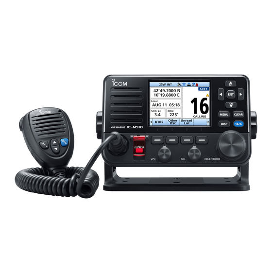
PANEL DESCRIPTION ■ Front panel display (p. 4) Speaker Speaker Speaker P W R DISTRESS KEY [DISTRESS] DISPLAY KEY [DISP] Hold down for 3 seconds to transmit a Push to switch the main screen between Distress call. (p. 21) the INFO, the Plotter, and the Highway screens. -
Page 16: Speaker Microphone
PANEL DESCRIPTION ■ Speaker Microphone Microphone Speaker P W R PTT SWITCH [PTT] (p. 13) Hold down to transmit, release to receive. Push to select the Favorite channels, change scanning direction or manually resume a scan. When the “FAV on MIC” item is set to “OFF,”... -
Page 17: Function Display (Info Screen)
PANEL DESCRIPTION ■ Function Display TIME AREA The current time and is displayed when (INFO screen) valid GPS data is received, or manually enter the time. When you switch the main screen between the INFO, the Plotter, and the Highway Indicator Description Displayed when a GPS... - Page 18 PANEL DESCRIPTION D Information area • Displayed when there are unread DSC messages. The following indicators are displayed in the • Blinks when a DSC message Information area. is received. Displayed when the “CH Auto Indicator Description Switch” in DSC Settings is set Displayed when receiving a to an option except “Accept.”...
-
Page 19: Software Keys
PANEL DESCRIPTION D Software key functions ■ Software Keys Various often-used functions are assigned Compose Distress [DTRS] (p. 22) to the Software Keys for easy access. The functions’ icons are displayed above the Push to display the “Compose Distress” Software Keys, as shown below. screen to select the nature of distress, then to make a call. - Page 20 While the Call channel or Channel 16 is CT-M500, and the CT-M500 must be displayed, push this key to return to the connected to the IC-M510. regular channel mode. LO/DX (p. 85) DSC Log (p.
-
Page 21: Preparation
PREPARATION ■ Entering the MMSI code The Maritime Mobile Service Identity (MMSI: DSC self ID) code consists of 9 digits. This initial code can be entered only once. After entering, it can be changed only by your dealer or distributor. If your MMSI code has already been entered, doing the steps below is not necessary. - Page 22 PREPARATION ■ Entering the MMSI code Enter your MMSI code again to confirm. Finish Push to set the entered code. • When your MMSI code is successfully entered, “MMSI enters the operating screen. Your MMSI code is also displayed on the opening screen. TRIAL MODE - Click here for more information...
-
Page 23: Basic Operations
BASIC OPERATIONS ■ Selecting a channel D Regular Channel D Channel 16 Channel 16 is the distress and safety channel. It is used to establish the initial contact with a station, and for emergency communications. Channel 16 is monitored during both Dualwatch and Tri-watch. -
Page 24: Weather Channels And Weather Alert
BASIC OPERATIONS ■ Weather channels and Weather Alert The transceiver has 10 preset Weather channels. The transceivers are capable* of monitoring broadcasts from the National Oceanographic and Atmospheric Administration (NOAA). The transceiver automatically detects a Weather alert tone on the selected weather channel, or while scanning. *When used within range of the broadcasts. -
Page 25: Adjusting The Volume/Squelch/Backlight/Display Mode
BASIC OPERATIONS ■ Adjusting the volume/squelch/backlight/display mode D Adjusting the volume level D Adjusting the squelch level Squelch enables the audio to be heard only while receiving a signal that is stronger than the set level. A higher level blocks weak signals, so that you can receive only stronger signals. -
Page 26: Setting The Call Channel
BASIC OPERATIONS ■ Setting the Call channel By default, a Call channel is set in each Channel Group. You can set your most often-used channel as your Call channel in each Channel Group for quick recall. Open the “Call Channel” screen. Call Channel channel. -
Page 27: Aquaquake Water Draining Function
BASIC OPERATIONS ■ AquaQuake Water Draining function AquaQuake Water Draining function removes water from the speaker grill by vibrating the speaker cone. CAUTION: DO NOT use the AquaQuake Water Draining function when an external speaker is connected. AquaQuake Hold down AquaQuake to turn ON the function. -
Page 28: Microphone Lock Function
BASIC OPERATIONS ■ Microphone Lock function accidental channel changes or functions access. the Lock function ON or OFF. TRIAL MODE - Click here for more information... -
Page 29: Scan Operation
SCAN OPERATION ■ Scan types Before starting a scan : • • Scan Type Normal Scan CH 04 CH 03 CH 05 CH 02 CH 01 Priority Scan CH 04 CH 03 CH 05 CH 16 CH 02 CH 01 When a signal is received: On Channel 16: On a channel other than Channel 16:... -
Page 30: Setting Favorite Channels
■ Setting Favorite channels Channel Group FAV ★ FAV ★ • FAV ★ TIP: ■ Starting a scan Example: Channel Group Scan Scan • • • Scan TIP: TRIAL MODE - Click here for more information... -
Page 31: Dualwatch/Tri-Watch
DUALWATCH/TRI-WATCH ■ Description Tri-watch Dualwatch CH 16 CH 16 When a signal is received: On Channel 16: On the Call channel: ■ Operation Dual/Tri-Watch Dual Watch TRI Watch Dual Watch TRI Watch • • Dual Watch TRI Watch TRIAL MODE - Click here for more information... -
Page 32: Digital Selective Calling (Dsc)
DIGITAL SELECTIVE CALLING (DSC) ■ DSC address ID D Entering an Individual or Group ID You can enter a total of 75 Individual IDs and 25 Group IDs, and assign names to them of up to 10 characters. Open the “Individual ID” or “Group ID” screen. [MENU] >... -
Page 33: Entering The Position And Time
D Deleting an entered ID Open the “Individual ID” screen. [MENU] > Settings > DSC > Individual ID Delete Select “STATION 2,” and then push • “Delete the ID. Are You Sure?” is displayed. Push to delete. Push Cancel to cancel the deletion. •... -
Page 34: Sending Dsc Calls (Distress)
DIGITAL SELECTIVE CALLING (DSC) ■ Sending DSC calls (Distress) A Distress call should be sent if, in the opinion of the captain, the ship or a person is in distress and requires immediate assistance. NEVER MAKE A DISTRESS CALL IF YOUR SHIP OR A PERSON IS NOT IN AN EMERGENCY. - Page 35 D Regular call Push DTRS • The “Compose Distress” screen is displayed. Push [ENT] or [CH/ENT] to enter the Nature selection mode. Select the nature of the Distress, and then push [ENT] • The setting is saved and returns to the previous screen. If no valid GPS data is being received, select “Position,”...
- Page 36 DIGITAL SELECTIVE CALLING (DSC) D Distress Cancel call If you have accidentally made a Distress call, or made an incorrect Distress call, Cancel • The screen to the right is displayed. Push • The Distress Cancel call is sent. • Channel 16 is automatically selected.
- Page 37 D Sending a Distress Relay acknowledgment received. • An alarm sounds. • The screen to the right is displayed. Alarm OFF Push any to turn OFF the alarm. Accept Push • The received information is displayed. Push • The call contents screen is displayed. Push Call •...
-
Page 38: Sending Dsc Calls (Other)
DIGITAL SELECTIVE CALLING (DSC) ■ Sending DSC calls (other) NOTE: To ensure proper DSC operation, be sure to correctly adjust the “CH 70 SQL Level” item on the Menu screen. (p. 47) D Sending an Individual call NOTE: You can also compose an Individual call to an AIS target on the Plotter screen or the AIS list. - Page 39 • An alarm sounds. • The screen to the right is displayed. 10. Push Alarm OFF to turn OFF the alarm. • The channel assigned in step 7 is automatically selected. If the called station cannot use the channel that you station.
- Page 40 DIGITAL SELECTIVE CALLING (DSC) D Sending an All Ships call All Ships that have DSC transceiver use Channel 70 as their listening channel. When you Call. Other DSC Push • The “Compose Non-Distress” screen is displayed. You can also display the “Compose Non-Distress” screen by selecting the “Other DSC”...
- Page 41 D Sending a Group call You can send a Group call to a pre-entered group address, or manually enter the address before sending. (p. 19) Other DSC Push • The “Compose Non-Distress” screen is displayed. You can also display the “Compose Non-Distress” screen by selecting the “Other DSC”...
- Page 42 DIGITAL SELECTIVE CALLING (DSC) D Sending a Test call channels. When you cannot avoid testing on a Distress or safety channel, you should indicate that these are test calls. involved. Other DSC Push • The “Compose Non-Distress” screen is displayed. You can also display the “Compose Non-Distress”...
- Page 43 D Sending a Test Acknowledgment After a Test call is being received, push Alarm OFF turn OFF the alarm. Accept Push • The received call’s information is displayed. Push • Call Push • “Transmitting Test ACK” is displayed. Push STBY , and then push to return to the operating screen.
- Page 44 DIGITAL SELECTIVE CALLING (DSC) D Sending a Position Request call/Polling Request call the presetting. • • communication area, or not. Example: Sending a Position Request call Push Other DSC • The “Compose Non-Distress” screen is displayed. You can also display the “Compose Non-Distress” screen by selecting the “Other DSC”...
- Page 45 D Sending a Position Reply call calling station. (p. 46) to turn OFF the alarm. Alarm OFF • The received call’s information is displayed. Ignore Ignores the call and returns to the operating screen. • The call is saved in the DSC Log. •...
- Page 46 DIGITAL SELECTIVE CALLING (DSC) Accepts the call. Accept • Displays the received call’s information. • The call is saved in the DSC Log. Push ACK Able ACK Unable , then push Call Closes the call, and then STBY returns to the operating screen.
- Page 47 D Sending a Polling Reply call/Position Report Reply call • When “Polling ACK” is set to “Auto,” the transceiver automatically sends the call. • Example: Sending a Polling Reply call Alarm OFF to turn OFF the alarm. Accept Push • Enters the DSC Task mode. Push •...
-
Page 48: Receiving Dsc Calls (Distress)
DIGITAL SELECTIVE CALLING (DSC) ■ Receiving DSC calls (Distress) calls. When you receive a call, an emergency alarm sounds. NOTE: When a Distress call is received: • The emergency alarm sounds until you turn it OFF. • Alarm OFF Push to turn OFF the alarm. - Page 49 When a Distress acknowledgment is received: Alarm OFF push to turn OFF the alarm. Close Window Push • The received information is displayed. Accept Push • The received information is displayed. STBY Push • “Terminate the procedure. Are you sure?” is displayed.
- Page 50 DIGITAL SELECTIVE CALLING (DSC) D Receiving a Distress Relay call When a Distress Relay call is received: • An alarm sounds. • • “ ” blinks. Alarm OFF Push any Ignore The call is saved in the DSC Log. “ ”...
-
Page 51: Receiving Dsc Calls (Other)
■ Receiving DSC calls (other) • Individual call (p. 38) • • Group call / All Ships call (p. 39) • • • station. ( [MENU] > Settings > DSC > Auto ACK (p. 46)) as described in this section. D Receiving an Individual call When an Individual call is received: •... - Page 52 DIGITAL SELECTIVE CALLING (DSC) D Receiving a Group call or All Ships call When a Group call is received: • An alarm sounds. call is received) • When an All Ships call is received: • An alarm sounds. • Alarm OFF Push to turn OFF the alarm.
- Page 53 D Receiving a Position Request call (May not be used, depending on the presetting) NOTE: Even if the Auto ACK function is set to “Manual,” after receiving a Distress automatically sent to the calling station. When a Position Request call is received: •...
- Page 54 DIGITAL SELECTIVE CALLING (DSC) D Receiving a Test call/Position Report call Example: Receiving a Test call • An alarm sounds. • Alarm OFF Push to turn OFF the alarm. Ignores the call and returns to the operating Ignore screen. • The call is saved in the DSC Log. •...
- Page 55 D Receiving a Test acknowledgment/Position Reply call /Polling Reply call Example: Receiving a Test acknowledgment • An alarm sounds. • blinks. • “ ” blinks. Alarm OFF Push to turn OFF the alarm. 2. Push Close Window • The received information is displayed. Push STBY •...
-
Page 56: Dsc Log
DIGITAL SELECTIVE CALLING (DSC) ■ DSC Log D Received DSC Log The transceiver saves up to 30 received Distress call messages and 50 received “Others” call messages in your DSC Log. On the operating screen, “ Open the “DSC Log” screen. [MENU] >... -
Page 57: Multiple-Task Mode
■ Multiple-task mode If the Multiple-task function is enabled, the transceiver can hold up to 7 tasks. You can the Multiple-task mode, select “Multiple” in the “Procedure” on the Menu screen. (p. 47) [MENU] > Settings > DSC > Procedure When the Multiple-task mode is activated, Task List is displayed on the operating screen. - Page 58 DIGITAL SELECTIVE CALLING (DSC) D Task list Task List You can display the task list screen by pushing The number of tasks is displayed at the top of the screen. The number of tasks STBY Delete Active Hold INFO TRIAL MODE - Click here for more information...
-
Page 59: Dsc Settings
■ DSC Settings CH Auto Switch On the “DSC” screen, you can make settings of the DSC call related items. channel, or ignore the call. [MENU] > Settings > DSC After receiving a DSC call, the transceiver remains on the operating Position Input channel for 10 seconds. - Page 60 DIGITAL SELECTIVE CALLING (DSC) ■ DSC Settings Alarm Status Self Check Test The Self-Test sends DSC signals to the each type of DSC call. receiving AF circuit to compare the sending Safety and receiving signals at the AF level. Routine Warning Push [ENT] to start the Self-Test.
-
Page 61: Making An Individual Call To An Ais Target
■ Making an Individual call to an AIS target D Selecting an AIS target on the IC-M510 You can compose an Individual call to an AIS target selected on the Plotter screen or the AIS list. NOTE: The AIS information can be input to the transceiver through the NMEA0183 or NMEA2000 sentence source. - Page 62 DIGITAL SELECTIVE CALLING (DSC) ■ Making an Individual call using an AIS transponder Using an AIS transponder Using an AIS transponder Transponder operation: Select an AIS target on the plotter display, Target, Danger, or Friends list screen. details. • Select “Send DSC,” and then push [ENT]. •...
-
Page 63: Ais Function
AIS FUNCTION NOTE: ■ About AIS Vessel Information ■ AIS classes • • • TRIAL MODE - Click here for more information... -
Page 64: Using The Plotter Screen
■ Using the Plotter screen • Range Target Details Details Stop NAV Stop MOB Anchor Stop Anchor NOTE: Plotter Plotter TRIAL MODE - Click here for more information... - Page 65 D Plotter screen TARGET ICONS Icon Description DISPLAY TYPE North up/Course up YOUR VESSEL ICON COMPASS TRIAL MODE - Click here for more information...
- Page 66 DISPLAY FILTER INDICATOR Target Display Indicator Description NAVIGATION LINE TARGET BOX Target Details VESSEL TRACK ANCHOR WATCH • • DISPLAY RANGE • • Range TRIAL MODE - Click here for more information...
-
Page 67: Using The Ais List Screen
■ Using the AIS list screen • • • Friend Details Disp on Plotter Sort NOTE: TRIAL MODE - Click here for more information... - Page 68 D Target/Friends List screen D Danger list screen Danger CPA or TCPA THE NUMBER OF TARGETS DANGER TARGET INFORMATION • THE NUMBER OF TARGETS • TARGET INFORMATION • • • • TRIAL MODE - Click here for more information...
-
Page 69: Setting A Friend
■ Setting a Friend D Entering an ID D Editing an ID Friends List Using the Friends List: Delete Friends List • D Deleting an ID TIP: Friends List • • Delete • • Finish • Selecting in the Target List or Danger List: Target List Danger List Friend... -
Page 70: About The Detail Screen
■ About the Detail screen Friend MMSI D Contents list NOTE: Class A and SAR vessel Class B TRIAL MODE - Click here for more information... - Page 71 Width AtoN and AtoN virtual AIS-SART, AIS-MOB, and EPIRB-AIS Base station Waypoint SAR aircraft TRIAL MODE - Click here for more information...
-
Page 72: Ais Settings
■ AIS settings North up/Course up CPA/TCPA Alarm Target Display • Approach • Lost Audible Alarm • Approach • Lost TCPA TRIAL MODE - Click here for more information... - Page 73 Friends Slow Warn Friends List Friends Alarm • Function • Function • Speed • Audible Alarm NOTE: • Range TRIAL MODE - Click here for more information...
- Page 74 ■ ID Blocking • Entering an ID ID Blocking • • TIP: • • • Finish • Editing an ID ID Blocking Edit • • Deleting an ID ID Blocking Edit • TRIAL MODE - Click here for more information...
-
Page 75: Other Functions
OTHER FUNCTIONS NOTE: For the other functions, the transceiver must be receiving valid GPS signals, or your position must be entered. (p. 20) ■ Waypoint Waypoints are GPS position data points of places you want to go to, the position of your own vessel, or of a vessel you received a DSC call from. - Page 76 D Entering a waypoint Position information that you want to memorize can be added as a waypoint. NOTE: You can also add your current position as a waypoint by pushing Open the “Waypoint” screen. [MENU] > Navigation > Waypoint Push to add a waypoint.
- Page 77 D Editing a waypoint A waypoint’s name, latitude, longitude data can be edited. You cannot edit the waypoint that is being used for navigation. Open the “Waypoint” screen. [MENU] > Navigation > Waypoint Push to Sort sort the waypoints by Name or Range. Select Edit See steps 3 ~ 9 in “Entering a waypoint”...
-
Page 78: Mob (Man Overboard)
■ MOB (Man Overboard) You can enter a Man OverBoard (MOB) waypoint into the transceiver with its GPS position data, as soon as a person has fallen into the water and needs to be rescued. This enables you to reach the MOB location even in the dark, or when you have lost visual contact. -
Page 79: Anchor Watch
■ Anchor Watch Anchor Watch is the function to sound an alarm when your vessel is at anchor and has drifted. D Starting Anchor Watch Push Anchor to start the Anchor Watch mode. • (a red circle) is displayed as the start position of anchor watch. -
Page 80: Navigation
■ Navigation The transceiver assists you to navigate to a selected destination. The function works only when the transceiver is receiving valid GPS signals. The function cannot work while in the MOB mode. NOTE: The Navigation function is a supplemental aid to navigation only, and is not intended to be a substitute for primary navigation equipment. - Page 81 Selecting in the AIS list: Open the list screen. Target/Danger/Friend list Push • “Start navigation. Are you sure?” is displayed. Push to start navigation. to start navigation. • The plotter screen is displayed, and the transceiver starts to navigate. • is displayed on the plotter screen.
- Page 82 D Highway screen Displays the highway information (only for watching). “Navigation OFF” is displayed on the mode is not used. STEERING DIRECTION Displayed when the vessel crosses the XTE (Cross Track Error) limit line. XTE LIMIT LINE Displays the limit line that marks when NAVIGATION LINE Displays a line from the start position of YOUR VESSEL ICON...
- Page 83 D Navigation settings Navigation settings can be customized in “Navigation” on the Menu screen. [MENU] > Settings > Navigation Track Anchor watch Display Audible Alarm You can select whether or not to display You can select whether or not to sound the vessel track on the plotter display.
-
Page 84: Lost Target
■ Lost target the vessel last transmitted data, as described below. The “Lost target” icon disappears from the plotter display 6 minutes and 40 seconds after the vessel was regarded as a “Lost target.” Ask your dealer for details. The criteria to become a Lost target •... -
Page 85: Using The Intercom
■ Using the Intercom communicate between the deck and the cabin. The ™ device. • Transmitting is disabled while using the intercom. • The received call audio is muted while using the intercom. [MENU] > Intercom • Call to sound the intercom beeps. •... -
Page 86: Using The Rx Hailer
■ Using the RX Hailer To use this function, the external hailer speaker must be connected to the CT-M500, and the CT-M500 must be See page 88 for details of the connection to the CT-M500. Connect an external hailer speaker as described on Push Rx Hailer adjust the volume level. -
Page 87: Using The Hailer
■ Using the Hailer You can talk without leaving the bridge by using the 2 way hailer function. To use this function, the external hailer speaker must be connected to the CT-M500, and the CT-M500 must be See page 88 for details of the connection to the CT-M500. Connect an external hailer speaker as described on •... -
Page 88: Using The Horn Function
■ Using the Horn function D Automatic Foghorn function The Automatic Foghorn function sounds a horn repeatedly until the function is turned OFF. The foghorn outputs from the hailer speaker. To use this function, the hailer speaker must TYPE USAGE PATTERN One 5-second Motor vessel... -
Page 89: Using The Voice Scrambler
D Horn Volume function Horn Volume foghorn level. D Manual Horn function Manual Horn Horn to sound a horn. • While holding down Horn , the horn sounds, and the screen shown to the right is displayed. To adjust the horn volume level, push VOL to open NOTE: receive functions are disabled. -
Page 90: Command Microphone Operation
■ Command microphone operation to the transceiver. Push screen. D Highway screen D Plotter screen XTE LIMIT LINE TARGET BOX YOUR VESSEL ICON When your vessel moves less than 2 YOUR VESSEL ICON knots per hour, is displayed. The vessel icon automatically points in RANGE the direction your vessel is heading, in 45 degree steps. - Page 91 D Command microphone Menu screen items These items are displayed only on the Command microphone screen. Use the command microphone keys to make the settings. Display Contrast [MENU] > Settings > Configuration > Display Contrast Adjusts the contrast of the Command microphone’s display in 8 steps. (Only in the Day Mode) Soft key/Dial assignment [MENU] >...
-
Page 92: Menu Screen
MENU SCREEN ■ Using the Menu screen The Menu screen is used to set items, select options, and so on for the transceiver’s functions. D Menu screen operation Example: Setting the key beep to “OFF.” Push [MENU]. • The Menu screen is displayed. •... - Page 93 D Menu screen items See the referred pages for each items. Menu Submenu Item Reference – Nature p. 21 Distress Position p. 20 Msg Type p. 25 – Mode p. 20 – – p. 45 Plotter p. 51 – p. 55 –...
- Page 94 D Menu screen items Menu Submenu Item Reference Backlight p. 82 p. 78 p. 82 p. 82, 78 p. 82 p. 83 p. 78 p. 73 p. 83 Scan Type Scan Timer p. 84 Settings p. 85 p. 46 p. 47 Procedure Target Display p.
-
Page 95: Menu Items Description
Menu Submenu Item Reference Track Navigation p. 70 Settings p. 85 Function p. 88 p. 93 – – p. 87 ■ Menu items description D GPS Info Key Assignment Soft Key 1~16 Displays your position, date, time, functions to display, and their order. You time. - Page 96 ■ Menu items description Noise Cancel Inactivity Timer noise components in the received or The transceiver automatically returns to the transmitted signal. Set the function for both operation screen if you push no key for the receiving and transmitting. set period of time for each mode. OFF: Not DSC Related components in the received...
- Page 97 • Radio Call Channel [MENU] > Settings > Radio Scan Type transceiver version. Selects the scan type. The default setting See page 13 for details. version. WX Alert See page 16 for details. For the Normal Scan: Scans all Favorite channels in the selected channel group.
- Page 98 ■ Menu items description • NMEA FAV on MIC [MENU] > Settings > NMEA NMEA 0183 Select the data transfer speed for each port through only the Favorite channels. to receive data from external devices. 4800 bps: Select to receive position data from an external GPS receiver.
- Page 99 Compatible PGN list Receive Transmit 059392 059392 059904 059904 060160 060416 Transfer Management Management 060416 060928 126208 060928 Function 126464 065240 126993 126208 126996 126996 126998 129026 129026 Update Update Update Update 129029 GNSS (Global Navigation Satellite 129029 GNSS (Global Navigation Satellite System) Position Data System) Position Data System) Position Data...
- Page 100 ■ Menu items description D Radio Info [MENU] > Radio Info Displays your transceiver’s information, TRIAL MODE - Click here for more information...
-
Page 101: Wlan Setting
WLAN SETTING IC-M510 can expand the functions such as NMEA 2000, Hailer, and so on by connecting to the CT-M500 with WLAN. IC-M510 can also be connected with mobile devices to communicate. NOTE: Install the transceiver within approximately 15 meters (49.2 ft) from the CT-M500, and in a place where there are no obstacles between the transceiver and the CT-M500. - Page 102 WLAN SETTING D Access Point mode TIP: • Select to enter numbers and letters, and enter symbols. • • Push [ENT] or [CH/ENT] to enter the selected character. • ENT] to move the cursor. Set items SSID: Enter the SSID. Up to 32 characters can be entered.
- Page 103 WLAN SETTING • “CT-M500” screen is displayed. Select “WLAN Setup” then push [ENT], [CH/ENT], or • “WLAN will be temporarily disconnect during this operation.”, or “This menu resets the CT-M500. Also, WLAN is temporarily disconnect.” is displayed. 10. Push • The transceiver starts searching the devices connected to the CT-M500 network.
- Page 104 WLAN SETTING D Client mode CT-M500 and a mobile device can connect to IC-M510 by the user supplied access point. Set the CT-M500 in the “CT-M500 settings” of the IC-M510. Access point (User supplied) CT-M500 RS-M500 IC-M510 Open the “Configuration” screen.
-
Page 105: Power Link Function
IP address of the mobile device. ■ Power Link function You can set whether the CT-M500 is automatically turned ON or OFF when the IC-M510 is turned ON or OFF. Open the “Power Link” screen. [MENU] > Settings > WLAN > Advanced Settings >... -
Page 106: Reset The Wlan Settings
• WLAN settings and the CT-M500?” is displayed. Push to reset the CT-M500 WLAN Settings and the IC-M510 Advanced Settings. ■ WLAN Information transceiver and the CT-M500. [MENU] > Settings > WLAN > Information TRIAL MODE - Click here for more information... -
Page 107: Connections And Maintenance
CONNECTIONS AND MAINTENANCE ■ Supplied accessories For mounting bracket For mounting bracket Mounting bracket DC power cable Knob bolts Flat washers (M5) Screws Spring washers (M5) (5 × 20 mm) Microphone Microphone hanger and screws (3 × 16 mm) Warning sticker NOTE: depending on the transceiver version. -
Page 108: Connections
CONNECTIONS AND MAINTENANCE ■ Connections GPS ANTENNA CONNECTOR Connects to an optional GPS antenna. NOTE: • The GPS sentences input from this connector are given priority to over the sentences input from the built-in GPS receiver. • Be sure the GPS antenna is positioned where it has a clear view to receive signals from satellites, and adhesive pad. -
Page 109: Cleaning
CONNECTIONS AND MAINTENANCE AF OUT LEADS ■ Connecting to the MA-510TR Connect the transceiver to the MA- 510TR using the accessory cable. After NOTE for NMEA In/Out and AF Out connecting, an Individual DSC call can leads: The connectors are attached be made to the AIS target using the to keep the leads together. -
Page 110: Mounting The Transceiver
CONNECTIONS AND MAINTENANCE ■ Mounting the transceiver D Using the supplied mounting bracket You can mount the transceiver on a dashboard using the universal mounting bracket supplied with your transceiver. CAUTION: KEEP the transceiver and microphone at least 1 meter (3.3 ft) away from the vessel’s magnetic navigation compass. -
Page 111: Installation
CONNECTIONS AND MAINTENANCE ■ MBF-7 installation The optional MBF-7 (less than 20 mm thick), such as an instrument panel. NOTE: Install the transceiver and/or microphone more than 1 meter from the vessel’s magnetic navigation compass. Using the template on page 110, carefully cut a hole in the instrument panel, or wherever you plan to mount the transceiver. -
Page 112: Microphone Installation
CONNECTIONS AND MAINTENANCE ■ MBF-7 installation Tighten the locking nuts (rotate counterclockwise) so that the transceiver is securely mounted in position, as shown to the right. (Torque: 2 N•m) Locking nut Connect the antenna and power cable, and then return the instrument control panel to its original place. - Page 113 CONNECTIONS AND MAINTENANCE Mounting base 5 mm, inch 2 mm, 1/16 inch Gasket TRIAL MODE - Click here for more information...
-
Page 114: Specifications And Options
SPECIFICATIONS AND OPTIONS ■ • • • • • • • • • • • • • • • • • TRIAL MODE - Click here for more information... - Page 115 • • • • • • • • • • • • • • • • • TRIAL MODE - Click here for more information...
- Page 116 156 (6.1) unit: mm (inch) 175 (6.9) 38.6 17.6 (0.6) (1.5) (0.7) TRIAL MODE - Click here for more information...
-
Page 117: Options
■ • • • ™* • • • • • • • • TRIAL MODE - Click here for more information... -
Page 118: Troubleshooting
TROUBLESHOOTING The transceiver does not turn ON. Bad connection to the power supply. Check the connection to the transceiver and power supply. (p.96) The fuse is blown. Repair the problem, and then replace the fuse. (p. 96) Little or no sound comes from the speaker. Squelch level is set too high. - Page 119 Turn ON the WLAN function. (p. 88) SSID is set incorrectly. Check the SSID on both the IC-M510 and the access point. CT-M500 is a bad connection to the power supply. Check the connection to the CT-M500 and power supply.
-
Page 120: Channel List
CHANNEL LIST ■ For IC-M510 NOTE: When the “Channel Display” is set to “3 digits” in the Radio setting, the channel number is displayed in 3 digits. See page 85 for details. (For example: “1001” is displayed as “01A.”) *1 Low power only. - Page 121 CHANNEL LIST *1 Low power only. Channel Number Frequency (MHz) Frequency (MHz) Frequency (MHz) *2 RX only. Transmit Receive *3 Momentary High Power. 1021 1021 1021 157.050 157.050 RX only RX only 2021 161.650 157.100 161.700 1022 1022 1022 157.100 157.100 157.150 161.750...
- Page 122 CHANNEL LIST ■ For IC-M510 Channel Number Frequency (MHz) Frequency (MHz) Frequency (MHz) Transmit Receive 156.925 161.525 1078 1078 1078 156.925 156.925 RX only RX only 2078 161.525 156.975 161.575 1079 1079 1079 156.975 156.975 RX only RX only 2079 161.575...
-
Page 123: Template
TEMPLATE 21 32 93 (3 11 32 110 (4 Unit: mm (inch) TRIAL MODE - Click here for more information... - Page 124 TRIAL MODE - Click here for more information...
- Page 125 INDEX Accessories Call channel Detail screen....57 Speaker Radio settings ..84 Distress call Microphone...3 Selecting ....10 Cancel call ....23 Supplied Setting.....13 Receiving ....35 accessories ..94 CH 70 SQL Level, DSC Regular call .....22 Settings ....47 Sending....21 Access Point mode..88 Channel Simple call....21 Software Key...23 About AIS ....50 Channel area ....5...
- Page 126 INDEX Hailer ......74 MA-510TR Panel Description ..2 Highway....69, 77 Connecting....96 Plotter Horn......75 Man Overboard (MOB) Description ....51 Starting....65 Using.......51 Stopping....65 Polling ID Blocking MBF-7 installation..98 Reply call, Deleting....61 Menu screen receiving .....42 Editing .....61 Description ....82 Reply call, sending...34 Inactivity Timer Items .......80 Request call, ...83...
- Page 127 INDEX Scan Waypoint Priority.....16 Deleting....64 Starting....17 Editing .....64 Types ......16 Entering....63 Scan Timer List ......62 Navigating ....64 Radio settings ..84 Scan Type Weather Alert....11 Radio settings ..84 Weather channels..11 Self Check Test WLAN Information ..93 (DSC Settings)...47 WLAN Reset....93 Simple call, WX Alert Distress call ..21...
- Page 128 A7625D-1EX-1a 1-1-32 Kamiminami, Hirano-ku, Printed in Japan Osaka 547-0003, Japan © 2021 Icom Inc. Jun. 2021 TRIAL MODE - Click here for more information...