Icom IC-M504 Instruction Manual
Vhf marine transceiver
Hide thumbs
Also See for IC-M504:
- Instruction manual (80 pages) ,
- Service manual (35 pages) ,
- Service manual (6 pages)
Table of Contents
Advertisement
Quick Links
Advertisement
Table of Contents

Related Manuals for Icom IC-M504


Summary of Contents for Icom IC-M504
- Page 1 INSTRUCTION MANUAL VHF MARINE TRANSCEIVER iM504...
-
Page 2: Important
IC-M504. We want to take a couple of moments of your time to thank you for making the IC-M504 your radio of choice, and hope you agree with Icom’s philosophy of “technology first.” Many EXPLICIT DEFINITIONS hours of research and development went into the design of your IC-M504. -
Page 3: In Case Of Emergency
IN CASE OF EMERGENCY NOTE A WARNING STICKER is supplied with the transceiver. If your vessel requires assistance, contact other vessels and the Coast Guard by sending a Distress call on Channel 16. To comply with FCC regulations, this sticker must be affixed in such a location as to be readily seen from the operating USING CHANNEL 16 controls of the radio as in the diagram below. -
Page 4: Radio Operator Warning
RADIO OPERATOR WARNING FAILURE TO OBSERVE THESE LIMITS MAY ALLOW Icom requires the radio operator to meet the THOSE WITHIN THE MPE RADIUS TO EXPERIENCE RF FCC Requirements for Radio Frequency Expo- RADIATION ABSORPTION WHICH EXCEEDS THE FCC sure. An omnidirectional antenna with gain not MAXIMUM PERMISSIBLE EXPOSURE (MPE) LIMIT. -
Page 5: Table Of Contents
TABLE OF CONTENTS FOREWORD ..................i ■ Position and time programming ............21 IMPORTANT ..................i ■ Position and time indication ...........22 EXPLICIT DEFINITIONS ..............i ■ GPS information indication ............22 IN CASE OF EMERGENCY ............. ii ■ Distress call ................23 NOTE .................... -
Page 6: Precautions
3.3 ft (1 m) away from the vessel’s magnetic navigation with equipment that is not manufactured or approved by Icom. compass. Icom, Icom Inc. and the Icom logo are registered trademarks of Icom Incor- DO NOT use or place the transceiver in areas with tem- porated (Japan) in Japan, the United States, the United Kingdom, Germany, peratures below –4°F (–20°C) or above +140°F (+60°C) or,... -
Page 7: Operating Rules
OPERATING RULES D PRIORITIES (2) OPERATOR’S LICENSE A Restricted Radiotelephone Operator Permit is the license • Read all rules and regulations pertaining to priorities and most often held by small vessel radio operators when a radio keep an up-to-date copy handy. Safety and Distress calls is not required for safety purposes. -
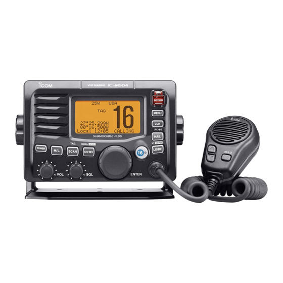
Page 8: Panel Description
PANEL DESCRIPTION ■ Front panel Speaker Function display (p. 4) r HAIL/RX SPEAKER KEY [HAIL•RX ➥ Push to turn the hailer mode ON or OFF. (p. 52) ➥ Push and hold for 1 sec. to turn the RX Speaker mode ON or OFF. - Page 9 PANEL DESCRIPTION u CHANNEL SELECTOR [DIAL•ENTER] o SQUELCH CONTROL [SQL] ➥ Rotate to select the operating channels, Set mode set- Rotate to set the squelch threshold level. (p. 8) tings, etc. (pp. 6–8, 55) !0 SCAN/TAG KEY [SCAN•TAG] (p. 13) ➥...
-
Page 10: Function Display
PANEL DESCRIPTION ■ Function display y CALL CHANNEL INDICATOR (pp. 6, 9) q w e r t Appears when the call channel is selected. u LOW BATTERY INDICATOR BUSY 25W CALL Blinks when the battery voltage drops to approx. 10 V DC LOC RX or below. -
Page 11: Microphone
PANEL DESCRIPTION ■ Microphone !1 POSITION INDICATOR ➥ Shows the current position data when a GPS re- Microphone ceiver is connected, or the time data is manually pro- grammed. Speaker • “??” may blink every 2 sec. instead of position data when the GPS position data is invalid. -
Page 12: Basic Operation
BASIC OPERATION ■ Channel selection D Channel 9 (Call channel) D Channel 16 Each regular channel group has a separate leisure-use call Channel 16 is the distress and safety channel. It is used for channel. The call channel is monitored during Tri-watch. The establishing initial contact with a station and for emergency call channels can be programmed (p. -
Page 13: Weather Channels
BASIC OPERATION D U.S.A., international and Canadian channels D Weather channels The IC-M504 is pre-programmed with 57 U.S.A., 57 inter- The IC-M504 has 10 pre-programmed weather channels. national and 61 Canadian channels. These channel groups These are used for monitoring broadcasts from NOAA (Na- may be specified for the operating area. -
Page 14: Receiving And Transmitting
BASIC OPERATION ■ Receiving and transmitting CAUTION: Transmitting without an antenna may dam- Simplex channels, 3, 21, 23, 61, 64, 81, 82 and 83 CAN- age the transceiver. NOT be lawfully used by the general public in U.S.A. wa- ters. q Push [POWER] to turn power ON. -
Page 15: Call Channel Programming
BASIC OPERATION ■ Call channel programming r Rotate [DIAL] to select the Call channel is used to select Channel 9 (default); however, CALL desired channel. you can program the call channel with your most often-used channels in each channel group for quick recall. 34°34.506N q While pushing and hold- 123°23.236W... -
Page 16: Channel Comments
BASIC OPERATION ■ Channel comments ■ Microphone Lock function The channels can be labelled with a unique alphanumeric ID The Microphone Lock function electrically locks [Y]/[Z] and [HI/LO] keys on the supplied microphone. This prevents ac- of up to 10 characters. cidental channel changes and function access. -
Page 17: Optional Voice Scrambler Operation
BASIC OPERATION ■ Optional voice scrambler operation D Activating the scrambler D Programming scrambler codes The optional voice scrambler provides private communica- When an optional scrambler unit is installed, 32 codes (1 to tions. In order to receive or send scrambled transmissions you 32) are available for programming. -
Page 18: Scan Operation
SCAN OPERATION ■ Scan types Set the TAG channels (scanned channel) before scanning. Scanning is an efficient way to locate signals quickly over a Clear the TAG channels which inconveniently stop scanning, wide frequency range. The transceiver has Priority scan and such as those for digital communication use. -
Page 19: Setting Tag Channels
SCAN OPERATION ■ Setting TAG channels ■ Starting a scan For more efficient scanning, add the desired channels as Set scan type (Priority or Normal scan) and scan resume TAG channels or clear the TAG for unwanted channels. timer in advance, using Set mode. (p. 55) Channels that are not tagged will be skipped during scan- q While pushing and holding [H/L], push [CH/WX•DUAL•... -
Page 20: Dualwatch/Tri-Watch
DUALWATCH/TRI-WATCH ■ Description ■ Operation Dualwatch monitors Channel 16 while you are receiving q Select Dualwatch or Tri-watch in Set mode. (p. 56) w Rotate [DIAL] to select the desired operating channel. on another channel; Tri-watch monitors Channel 16 and the call channel while receiving another channel. -
Page 21: Dsc Operation
DSC OPERATION ■ MMSI code programming u Rotate [DIAL] to set the specific 9-digit MMSI code. The 9-digit MMSI (Maritime Mobile Service Identity: DSC • Push [16•9] or [CH/WX•DUAL•U/I/C] to move the cursor for- self ID) code can be programmed at power ON. ward or backward, respectively. -
Page 22: Mmsi Code Check
DSC OPERATION ■ MMSI code check r Check the 9-digit MMSI (DSC self ID) code. The 9-digit MMSI (DSC self ID) code can be checked. q Push [MENU] to enter the DSC menu. --DSC Menu-- MMSI Check w Rotate [DIAL] to select “Set up,” push [DIAL•ENTER]. 123456789 --DSC Menu-- Select Item... -
Page 23: Dsc Address Id
DSC OPERATION ■ DSC address ID r Rotate [DIAL] to set the individual ID and ID name. A total of 100 DSC address IDs can be programmed and • Push [16•9] or [CH/WX•DUAL•U/I/C] to move the cursor for- named with up to 10 characters. ward or backward, respectively. -
Page 24: D Deleting Individual Id
DSC OPERATION D Deleting Individual ID q Push [MENU] to enter the DSC menu. r Rotate [DIAL] to select the desired ID name for deleting. w Rotate [DIAL] to select “Set up,” push [DIAL•ENTER]. --DSC Menu-- Select ID --DSC Menu-- John Select Item Paul... -
Page 25: D Programming Group Id
DSC OPERATION D Programming Group ID q Push [MENU] to enter the DSC menu. r Rotate [DIAL] to set the group ID and ID name. w Rotate [DIAL] to select “Set up,” push [DIAL•ENTER]. • The group ID is a unique number that you create for your group. The ID name is an associated text name for that group. -
Page 26: D Deleting Group Id
Push [MENU] to enter the DSC menu. r Rotate [DIAL] to select the desired ID name for deleting. w Rotate [DIAL] to select “Set up,” push [DIAL•ENTER]. --DSC Menu-- Select ID --DSC Menu-- Icom Select Item Group A Position Report ˘Group B Polling Request... -
Page 27: Position And Time Programming
DSC OPERATION ■ Position and time programming A distress call should include the ship’s position and time --DSC Menu-- data. If no GPS is connected, your position and UTC (Uni- Input Position versal Time Coordinated) time should be input manually. Latitude __°__.___N Null... -
Page 28: Position And Time Indication
[DIAL•ENTER] for 1 sec. displays the manually entered position and time. --GPS Info-- A GPS receiver appropriate for the IC-M504 is not supplied Push for 1 sec. by Icom. A GPS receiver with NMEA0183 ver. 2.0 or 3.01... -
Page 29: Distress Call
DSC OPERATION ■ Distress call e After transmitting the distress call, the transceiver waits A distress call should be transmitted, if in the opinion of the for an acknowledgment call on Channel 70. Master, the ship or a person is in distress and requires im- •... -
Page 30: D Regular Call
DSC OPERATION D Regular call ➥ A distress alert contains (default); • Nature of distress : Undesignated distress The nature of the distress call should be included in the dis- • Position data : GPS or manual input position data held tress call. - Page 31 DSC OPERATION Regardless of a GPS receiver (NMEA0183 ver. 2.0 or --DSC Menu-- 3.01) connection, the current position/time information Input UTC Time appears in steps r and t. If the information is not nec- __:__ Null essary to be changed, push [DIAL•ENTER] or [16•9] several times to skip the data input steps.
-
Page 32: Transmitting Dsc Calls
DSC OPERATION ■ Transmitting DSC calls i After receiving the acknowledgment, reply using the mi- crophone. To ensure correct operation of the DSC function, please make sure you set the squelch correctly. (p. 8) D Transmitting an individual call Received DistressACK The individual call function allows you to transmit a DSC sig- <Osaka Bay... - Page 33 DSC OPERATION e Rotate [DIAL] to select the desired pre-programmed r Rotate [DIAL] to select a desired intership channel, push [DIAL•ENTER]. i n div id ual ad dr es s o r “M a n u a l I n p u t ,” pu sh [DIAL•ENTER].
- Page 34 DSC OPERATION D Transmitting an individual acknowledgement y Standby on Channel 70 until an acknowledgement is re- ceived. When receiving an individual call, you can transmit an ac- knowledgement (‘Able to comply’ or ‘Unable to comply’) by --DSC Menu-- using the on screen prompts (see page 42 for details). You Individual Call TX Complete can also send an acknowledgement through the menu sys-...
-
Page 35: D Transmitting A Group Call
After the individual acknowledgement call has been Select Address Manual Input transmitted, the specified channel (specified by the call- ˘Icom ing station) is selected automatically when “Able to Group A Comply” is selected, or returns to the previous condition (before entering the DSC menu) when “Unable to... - Page 36 DSC OPERATION r Rotate [DIAL] to select a desired intership channel, push y After the group call has been transmitted, the following [DIAL•ENTER]. indication is displayed. • Intership channels are already preset into the transceiver in rec- ommended order. --DSC Menu-- Group Call TX Complete --DSC Menu--...
-
Page 37: D Transmitting An All Ships Call
DSC OPERATION D Transmitting an all ships call e Rotate [DIAL] to select the desired category, push Large ships use Channel 70 as their ‘listening channel.’ [DIAL•ENTER]. When you want to announce a message to all ships within • Output power of ‘Routine’ category is 1 W (low power) only. range, use the all ships call function. -
Page 38: D Transmitting A Position Request Call
DSC OPERATION D Transmitting a position request call t After the all ships call has been transmitted, the following indication is displayed. Transmit a position request call when you want to know a specific ship’s current position, etc. --DSC Menu-- All Ships Call q Push [MENU] to enter the DSC menu. - Page 39 DSC OPERATION e Rotate [DIAL] to select the desired pre-programmed individ- t After the position request call has been transmitted, the ual address or “Manual Input,” push [DIAL•ENTER]. following indication is displayed. • The ID code can be set in advance. (p. 17) •...
- Page 40 DSC OPERATION D Transmitting a position report call Regardless of a GPS receiver (NMEA0183 ver. 2.0 or Transmit a position report call when you want to announce your own position to a specific ship and to get an answer, etc. 3.01) connection, the current position/time information appears in steps r and t.
- Page 41 DSC OPERATION u After the position report call has been transmitted, the fol- lowing indication is displayed. --DSC Menu-- Input UTC Time __:__ Null --DSC Menu-- Position Report TX Complete <CLR 1sec˘Null Data> Now Waiting for ACK <CLR˘Exit / ENT ˘ OK> --DSC Menu-- Position Report Ready <CLR ˘...
- Page 42 DSC OPERATION D Transmitting a polling request call Transmit a polling request call when you want to know if a --DSC Menu-- specific vessel is within communication range. Select Address Manual Input q Push [MENU] to enter the DSC menu. John ˘Paul w Rotate [DIAL] to select “Polling Request,”...
- Page 43 DSC OPERATION D Transmitting a position request reply call t After the polling request call has been transmitted, the fol- Transmit a position request reply call when a position re- lowing indication is displayed. quest call is received. --DSC Menu-- When the automatic acknowledgement function is ON (p.
- Page 44 DSC OPERATION Regardless of a GPS receiver (NMEA0183 ver. 2.0 or 3.01) connection, the current position/time information --DSC Menu-- appears in steps r and t. If the information is not nec- Input UTC Time essary to be changed, push [DIAL•ENTER] or [16•9] __:__ Null several times to skip the data input steps.
- Page 45 DSC OPERATION D Transmitting a position report reply call e Rotate [DIAL] to select the desired individual address or Transmit a position report reply call when a position report ID code, push [DIAL•ENTER]. call is received. When the automatic acknowledgement function is ON (p. 48), --DSC Menu-- Select Address the transceiver automatically transmits a reply call after re-...
- Page 46 DSC OPERATION D Transmitting a polling request reply call e Rotate [DIAL] to select the desired individual address or Transmit a polling reply call when a polling request call is re- ID code, push [DIAL•ENTER]. ceived. --DSC Menu-- When the automatic acknowledgement function is ON (p. 48), Select Address the transceiver automatically transmits a reply call after re- John...
-
Page 47: Receiving Dsc Calls
DSC OPERATION ■ Receiving DSC calls D Receiving a distress call While monitoring Channel 70 and a distress call is received: ➥ The emergency alarm sounds for 2 minutes. Received • Push [CLR] to stop the alarm. DistressACK ➥ “Received Distress” appears in the display, then <Osaka Bay Channel 16 is automatically selected. -
Page 48: D Receiving An Individual Call
(depending on your replying condition see p. 28 for individual acknowledge- ment call procedure for details.); push [CLR] to ignore the individual call. Received Group <Icom <CLR ˘ Beep Off> SAFETY Received Individual D Receiving an all ships call <Paul... -
Page 49: D Receiving A Position Request Call
DSC OPERATION D Receiving a position request call While monitoring Channel 70 and a position request call is received: Received ➥ “Received POS Request” appears in the display. All Ships ➥ Push [CLR] to stop the beep, then push [DIAL•ENTER] <Paul <CLR ˘... -
Page 50: D Receiving A Polling Request Call
DSC OPERATION D Receiving a polling request call D Receiving a position report reply call While monitoring Channel 70 and a polling request call is While monitoring Channel 70 and a position report reply call received: is received: ➥ “Received POLL REQ” appears in the display. ➥... -
Page 51: Received Messages
DSC OPERATION ■ Received messages w Rotate [DIAL] to scroll to the desired message, push The transceiver automatically stores up to 20 distress mes- [DIAL•ENTER]. sages and 20 other messages. The messages can be used • Messages which are blinking have not been read. as an assistance to the logbook. -
Page 52: D Other Messages
DSC OPERATION D Other messages q Rotate [DIAL] to select “Other,” push [DIAL•ENTER]. e Rotate [DIAL] to scroll the message. • The stored message has various information, depending on the type of DSC call. --DSC Menu-- Select Message --DSC Menu-- Distress Individual Call ˘Other... -
Page 53: Dsc Set Mode
DSC OPERATION ■ DSC Set mode D MMSI code check r Set the offset time from the UTC (Universal Time Coordi- (See p. 16) nated) time by rotating [DIAL]. D Add Individual ID/Group ID (See pp. 17, 19) • Push [16•9] or [CH/WX•DUAL•U/I/C] to move the cursor for- D Delete Individual ID/Group ID (See pp. - Page 54 DSC OPERATION D Automatic acknowledgement r Rotate [DIAL] to turn the automatic acknowledgement This item sets the automatic acknowledgement function to ON or OFF. function ON or OFF. When a position request, position report or polling request --DSC Menu-- call is received, the transceiver automatically transmits a po- Auto ACK sition request reply, position report reply or polling reply call, ˘ON...
- Page 55 DSC OPERATION D NMEA Output r Rotate [DIAL] to select the NMEA Output function from Select an NMEA Output function from OFF, All Station or List Station. OFF, All Station or List Station. • List Station: Outputs the position data from the specified ves- When receiving position acknowledgment, the transceiver sels listed on the DSC individual ID screen.
-
Page 56: Other Functions
” or “ ” appears on the HM-157. Connect an optional command microphone as described on • To adjust the IC-M504’s speaker output level, rotate [VOL]. p. 63. • To adjust the HM-162’s speaker output level, rotate [SELEC- • Transmitting is impossible during Intercom operation. -
Page 57: Rx Speaker Function
■ RX Speaker function • While in the Intercom mode, the transceiver functions The IC-M504 has an RX Speaker function. When this func- (transmit and receive) are interrupted. If the transceiver tion is turned ON, the received audio can be heard on the is in transmit condition, the Intercom function is not avail- deck or tower via a hailer speaker. -
Page 58: Hailer Operation
■ Hailer operation • While in the hailer mode, the transceiver functions (trans- The IC-M504 has a hailer function for voice amplification mit and receive) are interrupted. If the transceiver is in over a loudspeaker, making it unnecessary to leave the transmit condition, the hailer function is not available. -
Page 59: Automatic Foghorn Function
OTHER FUNCTIONS ■ Automatic foghorn function The foghorn outputs from the hailer speaker. To use this The automatic foghorn function sounds a horn repeatedly function, the hailer speaker must be connected to the trans- until the function is turned OFF. Four patterns are available ceiver. - Page 60 OTHER FUNCTIONS q While pushing and holding [H/L], push [HAIL•RX ] to e R otat e [D IA L] to adjust th e fo ghor n level , push [DIAL•ENTER]. enter auto foghorn mode. • The foghorn level is adjustable in 30 steps. •...
-
Page 61: Set Mode
SET MODE ■ Set mode programming ■ Set mode items D Scan type Set mode is used to change the conditions of the transceiver’s functions: Scan type, Scan resume timer, Weather alert, Dual/ The transceiver has 2 scan types: Normal scan and Priority Tri-watch, Beep tone, LCD contrast, Automatic foghorn fre- scan. -
Page 62: Weather Alert
SET MODE D Weather alert D Beep tone A NOAA broadcast station transmits a weather alert tone You can select the silent operation by turning beep tones before important weather information. OFF or you can have confirmation beeps sound at the push When “ON”... - Page 63 SET MODE D Automatic foghorn frequency D Scrambler type The audio frequency of the automatic foghorn can be ad- (Appears when a scrambler unit is installed) justed to suit your preference. While this item is selected, When an optional scrambler unit is installed, the scrambler pushing [PTT] outputs the foghorn—...
-
Page 64: Connections And Maintenance
CONNECTIONS AND MAINTENANCE ■ Connections e EXTERNAL SPEAKER LEAD (Yellow) Connects to an external speaker. Outer conductor : Speaker (−) Inner conductor : Speaker (+) r HAILER/FOGHORN (–) LEAD (Black) Connects to a hailer speaker (25 W nominal at 13.8 V/4 ˘). t HAILER/FOGHORN (+) LEAD (Blue) Do not Connects to a hailer speaker (25 W nominal at 13.8 V/4 ˘). -
Page 65: Fuse Replacement
CONNECTIONS AND MAINTENANCE ■ Supplied accessories CAUTION: After connecting the DC power cable, NMEA IN/ Mounting bracket For mounting bracket OUT leads, external speaker lead and hailer/foghorn lead, Knob bolts Flat washers (M5) cover the connector and leads with an adhesive tape as shown below, to prevent water seeping into the transceiver. -
Page 66: Mounting The Transceiver
CONNECTIONS AND MAINTENANCE ■ Mounting the transceiver D Using the supplied mounting bracket The universal mounting bracket supplied with your trans- • OVERHEAD MOUNTING ceiver allows overhead or dashboard mounting. • Mount the transceiver securely with the 4 supplied screws (5 ×... -
Page 67: Installation
IC-M504. r Attach the clamps on either side of the IC-M504. u Connect the antenna and power cable, then return the • Make sure that the clamps align parallel to the IC-M504’s body. instrument control panel to its original place. -
Page 68: Installation
CONNECTIONS AND MAINTENANCE ■ UT-112 installation CAUTION: DISCONNECT the DC power cable from the w Disconnect the flat cable and NMEA (4 pin) from J5 of the LOGIC unit. transceiver before performing any work on the trans- ceiver. Otherwise, there is danger of electric shock and/or LOGIC unit equipment damage. -
Page 69: Hm-162/Hm-157 Installation
CONNECTIONS AND MAINTENANCE ■ HM-162/HM-157 installation r Return the cables and screws to the original position. • Be sure not upside down the flat cable. CAUTION: • When re-assembling the case and tightening the screws, you must keep the specified torque (0.5±0.07 N.m). - Page 70 CONNECTIONS AND MAINTENANCE • HM-157 q Insert the supplied cable into the external microphone jack and tighten the cable nut as shown below. Mounting base Gasket Screw holes (approx. 2 (d) mm; ⁄ ˝) y The completed installation should look like this. •...
- Page 71 CONNECTIONS AND MAINTENANCE D HM-162 Mounting base Gasket...
- Page 72 CONNECTIONS AND MAINTENANCE D HM-157 Mounting base 5 mm; ⁄ ˝ 2 mm; ⁄ ˝ Gasket...
-
Page 73: Troubleshooting
TROUBLESHOOTING PROBLEM POSSIBLE CAUSE SOLUTION REF. The transceiver does • Bad connection to the power supply. • Check the connection to the transceiver. p. 58 not turn ON. No sound comes from • Squelch level is too high. • Set [SQL] to the threshold point. p. -
Page 74: Specifications And Options
SPECIFICATIONS AND OPTIONS ■ Specifications D Receiver D General • Receive system : Double conversion • Frequency coverage : Tx 156.025–157.425 MHz superheterodyne Rx 156.050–163.275 MHz • Sensitivity (12 dB SINAD) : 0.22 µV (typical) • Mode : FM (16K0G3E), DSC (16K0G2B) •... -
Page 75: Options
SPECIFICATIONS AND OPTIONS ■ Options • UT-112 • MB-75 voice scrambler unit flush mount kit Ensures private communications. 32 codes are available. For mounting the transceiver to a panel. Not available in some countries. • HM-162 ™ commandmic iii External microphone-type controller. Provides optional inter- com operation. -
Page 76: Channel List
CHANNEL LIST Channel number Frequency (MHz) Channel number Frequency (MHz) Channel number Frequency (MHz) Channel number Frequency (MHz) CAN Transmit Receive CAN Transmit Receive CAN Transmit Receive CAN Transmit Receive 156.050 160.650 157.050 161.650 156.425 156.425 157.325 157.325 156.050 156.050 21A 157.050 157.050 156.475 156.475 157.375 161.975... -
Page 77: Template
TEMPLATE R12 (Max.) MB-75 HM-157 HM-162 Unit: mm (inch) -
Page 79: Fcc Information
FCC INFORMATION • FOR CLASS B UNINTENTIONAL RADIATORS: This equipment has been tested and found to comply with the limits for a Class B digital device, pursuant to part 15 of the FCC Rules. These limits are designed to provide reason- able protection against harmful interference in a residential installation. - Page 80 A-6483H-1US-r Printed in Japan 2003–2010 Icom Inc. © 1-1-32 Kamiminami, Hirano-ku, Osaka 547-0003, Japan Printed on recycled paper with soy ink.
- Page 81 When the lcom MA-500TR is con- To ensure correct operation of the DSC function, make CLASS B AIS TRANSPONDER nected to your IC-M504/IC-M505/IC-M603/IC-M604 sure you correctly set the transceiver’s squelch. VHF MARINE , an individual DSC call can be transmitted to a TRANSCEIVER These instructions are based on using the IC-M604.