Advertisement
Table of Contents
- 1 Table of Contents
- 2 Section 1. INTRODUCTION
- 3 Section 2. GETTING STARTED
- 4 Section 3. INSTALLATION
- 5 Section 4. HARDWARE REFERENCE
- 6 Section 5. BASIC MOTION CONTROL CONCEPTS
- 7 Section 6. COMMUNICATING with the POSITIONER
- 8 Section 7. PROGRAMMING
- 9 Section 8. MAINTENANCE & TROUBLESHOOTING
- 10 Index
- Download this manual
sales@artisantg.com
artisantg.com
(217) 352-9330 |
|
Click HERE
Find the Parker / Compumotor PDHX15-E at our website:
Advertisement
Table of Contents

Related Manuals for Parker PDHX-E Series


Summary of Contents for Parker PDHX-E Series
- Page 1 (217) 352-9330 | Click HERE Find the Parker / Compumotor PDHX15-E at our website:...
- Page 2 PDHX-E Series Drive User Guide (PDHX15-E, PDHX15E-D) For engineering For engineering assistance in Europe: assistance in the U.S.: Parker Hannifin plc Parker Hannifin Corporation Electromechanical Division - Digiplan Compumotor Division 21 Balena Close 5500 Business Park Drive, Suite D Poole, Dorset...
- Page 3 Artisan Technology Group - Quality Instrumentation ... Guaranteed | (888) 88-SOURCE | www.artisantg.com...
- Page 4 The information in this user guide, including any apparatus, methods, techniques, and concepts described herein, are the proprietary property of Parker Digiplan or its licensors, and may not be copied, disclosed, or used for any purpose not expressly authorised by the owner thereof.
- Page 5 High voltages remain after power removed. Do not remove cover. No user-serviceable parts inside. Symbols used on the PDHX-E Series of drives have the following meanings: Refer to the Protective conductor terminal accompanying documentation Risk of electric shock Alternating current...
- Page 6 Product Type: PDHX15E, PDHX15E-D The above product is in compliance with the requirements of directives • 89/336/EEC Electromagnetic Compatibility Directive as amended by Directive 92/31/EEC The product is intended for use in the Commercial, Light Industrial and Industrial Environments as defined in the relevant EMC standards. This product is compliant with the Low Voltage Directive.
-
Page 7: Table Of Contents
INDEX ........................91 Associated Documentation This User Guide forms part of the documentation required to use the PDHX-E Series of stepper drives, it should be read in conjunction with the X150/X150E Software Reference User Guide (Part Number 1600.221.01) which provides details of individual commands. -
Page 8: Section 1. Introduction
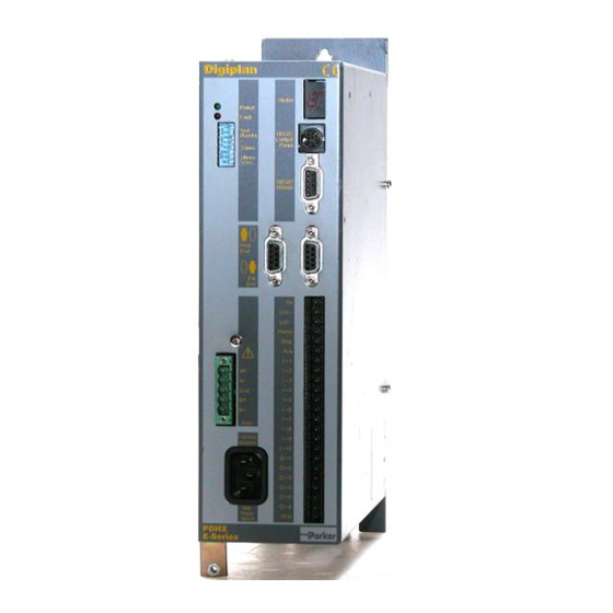
SECTION 1. INTRODUCTION Section 1. INTRODUCTION Product Description The PDHX15E is a single-axis packaged ministep drive incorporating an X150E position controller. The PDHX15E-D is also available with a built-in regenerative dump circuit. The drive is a chopper-regulated MOSFET design offering high performance in low and medium power applications. - Page 9 PDHX-E SERIES DRIVE USER GUIDE Artisan Technology Group - Quality Instrumentation ... Guaranteed | (888) 88-SOURCE | www.artisantg.com...
-
Page 10: Section 2. Getting Started
Section 2. GETTING STARTED What You Should Have Upon receipt, you should inspect your PDHX-E Series Drive system for obvious damage to its container. Report any damage as soon as possible. The items listed in Table 2-1 should be present and in good condition. To verify that you have the proper drive model, check the model number listed on the drive serial plate. - Page 11 Pre-installation Test This section provides procedures to help you to connect up your PDHX-E drive system for a pre-installation test. Please note the pre-installation test allows you to become familiar with the operation of the drive prior to permanent installation, it should only be set up and used by competent personnel familiar with installation of motion control equipment.
- Page 12 Power Status Fault Test RS232 Drive Standby RP240 switch Resolution Motor current RS232 RS232 Control RS485 Ext. Prim. Enc. Enc. LMT+ Pull-up the STOP input LMT- to enable the drive HOME STOP I -1 I -2 I -3 Motor Main connector I -4 I -5...
- Page 13 Motor and AC Power Connections 1. Connect the Motor WARNING - Electric Shock Hazard Ensure that AC power is disconnected before attempting to connect or disconnect the motor. Lethal voltages are present on the motor connectors. Fit the drive end motor connector to the corresponding socket, ensuring that the motor cable screen is anchored under the P-clip and the ferrite absorber is fitted in the position shown in Figure 2-2.
- Page 14 Motor rotation of 1 revolution confirms that the drive is operating correctly. If the motor fails to rotate, re-check all connections. If you do not discover the cause of the problem refer to the Maintenance & Troubleshooting section. At the end of testing remove power from the drive. Artisan Technology Group - Quality Instrumentation ...
- Page 15 Artisan Technology Group - Quality Instrumentation ... Guaranteed | (888) 88-SOURCE | www.artisantg.com...
-
Page 16: Section 3. Installation
Section 3. INSTALLATION Precautions During installation, take the normal precautions against damage caused by electrostatic discharges. Earthed wrist straps should always be worn. Power Connections Input power is taken directly from AC supplies via the front panel mounted IEC 3-way mains inlet socket. - Page 17 Drive-end connections Fit the ferrite absorber supplied over the motor cable. Connect the five leads in the motor cable to the motor connector as shown in Fig. 3-1. Expose a short length of the cable screen and anchor it to the drive using the metal P-clip located below the mains input connector. Locate the absorber between the P-clip and the motor connector, retaining it in place with the heat-shrink sleeving supplied.
- Page 18 The recommended components are produced by Parker Chomerics and are suitable for use with cable having an outside diameter up to 10mm. The specification is as follows: Chomerics part number H8FE-1115-NC Outside diameter 17.5mm Inside diameter 10.7mm Length 28.5mm Impedance at 25MHz...
- Page 19 With 4 lead motors the bipolar rating is quoted and this should match the criteria stated above. With 6 lead motors the unipolar rating is quoted, but for best performance of the PDHX-E Drives, the centre tap of each winding should be left unconnected and the connections made between the winding ends.
- Page 20 Motor Connections Motor connection details can be determined from Tables 3-1 and 3-2. For example, Figure 3- 3 shows the connection required to be made to a STEBON SDT 852-150-90 motor with its windings connected in parallel. The motor is viewed from the terminal box end with the end plate removed.
- Page 21 N.C. - no connection. MAKE TYPE A– NOTES Pacific Scientific 6-lead Black Orange Yellow White/Blk/Org, White/Red/Yel N.C. 8-lead Black Orange Yellow Link Wh/Blk & Wh/Org Link Wh/Red & Wh/Yel T.box Link 5 & 6,link 7 & 8 Slo-syn 8-lead Red/Wh Grn/Wh Link Black &...
- Page 22 For 6-lead motors, connections shown are for one half-winding. N.C. - no connection. MAKE TYPE A– NOTES Pacific Scientific 6-lead Black Wh/Blk/ Wh/Red/ Or & Yellow N.C. Orange Yellow 8-lead Black & Or & Red & Yel & Wh/Or Wh/Blk Wh/Yel Wh/Red T.box...
- Page 23 Drive Current Setting SWITCH SETTINGS PEAK CURRENT 5.0A 4.6A 4.3A 3.9A 3.6A 3.2A 2.9A 2.5A Table 3-3. Peak Current Settings Compumotor S and QM Motor Drive Settings When using Compumotor ‘S’ and ‘QM’ motors you will need to set the drive current settings as shown in Table 3-4.
- Page 24 Digiplan SM Motor Drive Settings Table 3-5 lists the PDHX15-E Drive current settings you need to make when using Digiplan ‘SM’ and STEBON motors. In Table 3-5, under ‘Motor Type’, a suffix ‘S’ refers to series connected and ‘P’ refers to parallel connected. Motor Type Switch settings Peak...
- Page 25 Controller Signals There are 5 front-panel connectors associated with control inputs and outputs as shown in the diagram. Their functions are as follows: 1. RS232/RP240 (8-way mini-DIN socket). This socket is normally used for the RP240 Remote Operator Panel but may also be used as an alternative RS232C connection from the host controller.
- Page 26 Main I/O Connector No screening requirements are necessary for EMC purposes, standard equipment wire may be used. Although, care should be taken to to avoid looping the wires around the mains inlet wire or other drive connections. Power Status Fault Test RS232 Drive...
- Page 27 Signal Name Function Signal Type CONNECTOR Secondary Encoder A Ext. encoder 9-way D-type Secondary Encoder B Secondary Encoder Z 5V ENC. +5V DC, 150mA max. Encoder GND A+/CLK+ Primary Encoder A Pri. encoder A-/CLK- 9-way D-type B+/DIR+ Primary Encoder B B-/DIR- Primary Encoder Z 5V ENC.
- Page 28 +24/5V (100mA) DC OUTPUT MAIN CONNECTOR LMT+ +Limit Switch Input LMT- -Limit Switch Input HOME Home Switch Input STOP Stop Input Registration Input I - 1 User Input 1 I - 2 User Input 2 I - 3 User Input 3 I - 4 User Input 4 I - 5...
- Page 29 In either case, the input is OFF (i.e. inactive) when in the open circuit condition. This condition is described as the logic 0 state and will return a ‘0’ in response to the input status request IS. Signal Type A Apply to all dedicated and user definable inputs.
- Page 30 Vuser Ext V External load BCX51 OUTn BCX54 Ext 0V Figure 3-7. NPN or PNP Output Configuration Output voltage levels will be determined by the value of the external voltage (Vuser) and the value of the connected load. Caution - Possibility of equipment damage The output circuit uses a connected pair of output transistors, consequently when the NPN transistor is used, but is turned OFF, the external user voltage (Vuser) must be no greater than the external voltage (Vs).
- Page 31 Signal Type E RS232 data signals. Signal Type F RP240 RS232 data signals. Signal Type G RP240 +5V DC supply (150mA max). Signal Type I Signal ground. Signal Type J RS485 data signals. Address Switch The address of the drive is set using an internally mounted bit switch. The switch may be accessed via the ventilation slots on the top of the drive - see Figure 3-8.
- Page 32 Mechanical/Environmental Enclosure Considerations The drive, its switch mode power supply and positioner are contained in a single case measuring 292mm high, 75mm wide and 224mm deep. Note: Enclosure depth does not take connector dimensions into account. These need an additional 60mm. Environmental Specifications Digiplan recommends you operate and store your PDHX Drive system under the following conditions:...
- Page 33 Selftest Switch1 The selftest switch is used to check the operation of the drive. Set to the ON position to cause the motor to rotate at slow speed. The default setting of selftest is OFF i.e. not selected. Standby Switch 2 Switch 2 determines the level of standby current.
- Page 34 Thumbwheel Interface This section assumes that you are using Parker's TM8 thumbwheel module. You can use up to 16 digits of the thumbwheel. The controller uses a multiplexed BCD input scheme to read the thumbwheel data. The commands and format that allow for the...
- Page 35 Define appropriate outputs for TM8 operation using the OUTnJ command. The TM8 is now ready for operation. Example The TM8 is wired as shown in Figure 3-9. Inputs 6 to 9 are to be used as data inputs. Input 10 is to be used as a sign input. Outputs 3 to 5 are to be used as strobe outputs.
- Page 36 TM8 Module +5 G I5 I4 I3 I2 I1O5 O4O3O2O1 Lmt+ Lmt- Home Stop Main I/O Connector I-10 Figure 3-9. Connections to TM8 Thumbwheel Module Using two TM8 Thumbwheels Wire the TM8s as shown in Figure 3-10. Configure as previously described. Output 6 is used to select which thumbwheel is to be read.
- Page 37 TM8 Module #2 TM8 Module #1 Main I/O TM8 Module TM8 Module +5 G I5 I4 I3 I2 I1O5 O4O3O2O1 +5 G I5 I4 I3 I2 I1O5 O4O3O2O1 Connector Lmt+ Lmt- Home Stop I-10 OPTIONAL SIGN BIT Figure 3-10. Connections to Dual TM8 Thumbwheel Modules Artisan Technology Group - Quality Instrumentation ...
-
Page 38: Section 4. Hardware Reference
Section 4. HARDWARE REFERENCE PDHX15-E Drive Specifications Parameter Value Amplifiers Type MOSFET Chopper Motor resolution 400, 1000, 2000 and 4000 steps/rev (user-selectable) Short circuit protection Phase-to-phase, across phases and phase to ground Peak output current 5A/phase, switch reduceable Standby current reduction To 80% or 50% of programmed peak value after 100ms (switch- selected) Nominal chopping frequency... - Page 39 Controller Specification Parameter Value Command Input RS232C (3-wire) or RS485 (2-wire, single-ended or 4-wire, differential) RS232 Type 3-wire (Tx, Rx, Gnd). Minimum voltage swing = ±3V Parameters 9600 baud, 8 data bits, 1 stop bit, no parity Connector 8-way mini DIN or 9-way D-type Configuration Up to 32 interfaces can be controlled from a single RS232C port.
-
Page 40: Section 5. Basic Motion Control Concepts
Section 5. BASIC MOTION CONTROL CONCEPTS Chapter Objectives This chapter is preliminary to the programming section and describes some of the basic concepts of motion control systems in general and the PDHX-E in particular. Motion Profiles In any motion control application the most important requirement is precise shaft rotation, whether it be with respect to position, time or velocity. - Page 41 position referenced, even while in incremental mode. However, the counter does have an upper limit just slightly more than 268,400,000 counts. Continuous Moves Continuous moves (MC command) cause the motor to accelerate and attain the specified velocity and then continue to move. To change velocity while the motor is moving use the V command.
- Page 42 At a velocity of 50 revs/sec TRIP Set defined Output when in position Program Operation When executing this program, the axis will first accelerate at 100 steps/rev to 10 revs/sec (1) and when it reaches a distance of 4000 steps (2), its speed will be reduced to 1 rev/sec (3) whilst it is waiting for the registration pulse.
- Page 43 have travelled half of the defined distance due to the acceleration setting of 1 rev/sec/sec. The motion profile for this move would look like this. Velocity (revs/sec) Vmax Vavg (= 0.5 Vmax) Time, seconds Figure 5-2. Triangular Profile Trapezoidal Profile A trapezoidal move profile results when the defined velocity is attained before the motor shaft has moved half of the specified distance.
- Page 44 The user may define a move profile using the MC command to establish the continuous mode. Velocity can be programmed on the fly by the V command. The positioner also has a mode MQ, which is like the preset move mode in that the move distance is pre-defined, but it is possible to change speed in the middle of the move as required based on a distance, input or time delay trigger.
- Page 45 When using SIM3 or SIM 4 operation for short moves it is possible to predict the number of steps the motor will take using the formula : Number of motor steps to move = CMR × no. of pulses received + prev. remainder ...
- Page 46 Position Maintenance By attaching an encoder to the load, Position Maintenance can be used to correct position errors between motor and encoder at the end of a move. The controller will detect the difference between the number of steps the motor was commanded to move and the number of steps reported by the encoder.
- Page 47 senses the movement of material passing through the rollers via a drive wheel, as shown in Figure 5-4. If slippage occurs driving the required length of material through the rollers the encoder count will disagree with the motor step count, therefore Position Maintenance can be used to give the motor more steps until the correct encoder count is achieved.
- Page 48 Interaction of Stall Detect and Position Maintenance If both Stall Detect and Position Maintenance are enabled and the motor is moved away from its expected position, a stall will occur or position maintenance will attempt to bring the motor back to position. The decision as to what happens is made as follows: If DPE (position error) >...
- Page 49 Program Storage The program memory is battery backed up RAM with memory retention of 10,000 hours. The RAM has 8K characters available for sequence storage and a write protect facility is provided. Programs are stored in variable length buffers and the total length cannot exceed 8K. Write Protection A write protection facility is incorporated for the protection of stored sequences and parameters stored by the SV command.
-
Page 50: Section 6. Communicating With The Positioner
Section 6. COMMUNICATING WITH THE POSITIONER Chapter Objectives The information contained in this chapter will enable you to set up communications with the positioner using an RS232C serial link. If more than one positioner is present in the system, details are provided on the connection of multiple positioners using the RS-232 Daisy Chain. Command Interface The interface is a three wire implementation (Tx, Rx, Ground) of RS232C. - Page 51 Switch settings for addresses 1 to 16 (switch 5 off) Address Sw 1 Sw 2 SW 3 Sw 4 1 (17) 2 (18) 3 (19) 4 (20) 5 (21) 6 (22) 7 (23) 8 (24) 9 (25) 10 (26) 11 (27) 12 (28) 13 (29) 14 (30)
- Page 52 Attach device identifiers to the front of the command. The Go (G) command instructs all units on the daisy chain to go, while 1G tells only unit #1 to go. When you use a single communications port to control more than one Controller, all units in the daisy chain receive and echo the same commands.
- Page 53 Unit 1 moves 25,000 steps, unit 2 moves 50,000 steps and unit 3 moves 100,000 steps. All three units use the same acceleration and velocity rates. Interactive operation with a PC/PLC To create a reliable, trouble free interactive RS232 communications control program between a PC/PLC and the serial interface you should note the following points : •...
- Page 54 number of coincidences, such as sending a status request just as the interface hits a limit, just as it starts decelerating etc. Any motion control requirement explicitly takes priority over communications under these circumstances, and can therefore cause a communications problem unless you wait for echoback. Also different issues of software may have different execution time characteristics which can make a routine based on delays work at one software issue, and not another.
- Page 55 • The status request command (R) can be used to provide helpful diagnostics. The responses generated by the interface are as follows: *R<CR> - ready for a command with no errors *S<CR> - ready for a command with function error *T<CR>...
- Page 56 [4] The E command is the enable RS-232 command which can easily be miss-typed as the F command which will lock out the keyboard. Cycling the power will not cure this problem since SV cannot be typed following a keyboard lock out. [5] The <space>1 in <space>1R is important.
- Page 57 RP240 MENU RECALL POWER CONTRAST INCREASE CONTRAST DECREASE Illuminated LEDs PAUSE ENTER CONTINUE STOP Figure 6-3. Status LEDs The other indicator is the two line, 40 character LCD display. This display can be controlled with specific Extended X Language commands. The Position Cursor (DPC) command allows the user to program the location of the cursor on the LCD display.
- Page 58 Step 3 Issue the DPC225 command (line 2, position 25) ENT ER T HE CYCL E COUNT Cursor Location Once the operator has been provided with the prompting message, the actual cycle count data is provided using the Read and Enable Numeric Keypad (VARn=NUM) or Read and Enable Function Keys (VARn=FUN).
- Page 59 Step 7 Press a 0 followed by an ENTER. ENT ER T HE CYCL E COUNT Cursor Location Once the cycle count has been entered, clear the display and enter text which allows an operator to choose a particular function (in this case a choice of parts). Step 8 DCLR0 command is issued.
- Page 60 Step 12 Issue the DTXT”PART1 PART2 PART3 PART4 PART5 PART6” command. This text serves as an operator menu for the function keys. Cursor Location WH I CH PAR DO Y U WAN PART 1 PART 2 PART 3 PART 4 PART 5 PART 6 Step 13...
- Page 61 Enabling STOP and PAUSE Keys In addition to the function keys and numeric keypad, there are three other keys. The STOP key, and the PAUSE and CONTINUE keys are enabled by default, and can be disabled by user commands. Typically, if an application uses the STOP key, the key will be enabled (DSTP1) in the power- up sequence.
- Page 62 Sequence #22 Sequence #22 prompts you for a password, and then transfers control to sequence #23. If the password is incorrect, control is passed to sequence #21. XE22 XD22 1DCLR0 1DPC100 1DTXT”ENTER CODE NUMBER xxxx” 1DPC118 VAR1=NUM IF(VAR1<1234 OR VAR1>1234) 1DPC220 1DTXT”WRONG NUMBER”...
- Page 63 Sequence #24 Sequence #24 simulates jogging. You can select CW or CCW jog options of either high or low velocity. The default jog velocities are stored in variables 20 and 21, which were assigned in sequence #63. The MENU RECALL key is used to exit Jog mode. XE24 XD24 VAR1=0...
- Page 64 1DPC100 1DTXT"THE LEDS BELOW WILL CHANGE STATE" 1DLED00000001 T1 1DLED00000011 T1 1DLED00000111 T1 1DLED00001111 T1 1DLED00011111 T1 1DLED00111111 T1 1DLED01111111 T1 1DLED11111111 T1 1DLED00000000 T1 VAR=0 The 10 input bits in sequence #25 correspond to the total number of Controller user inputs. Sequence #26 Sequence #26 sets up the learning mode for moves.
- Page 65 VAR1=0 Sequence #28 Sequence #28 prompts the operator to select the feed length, maximum speed and to count the number of items to be cut. XE28 XD28 1DCLR0 1DPC100 1DTXT"SELECT FEED LENGTH, MAX SPEED, AND COUNT" T2 1DCLR1 REPEAT VAR30=0 1DPC102 1DTXT"ENTER FEED LENGTH IN INCHES: (0-99.9)"...
- Page 66 1DPC125 1DVO3,4,2,0 1DPC202 1DTXT"YES" 1DPC236 1DTXT"NO" VAR22=FUN IF(VAR22>1) 1DCLR0 VAR30=1 UNTIL(VAR30=0) 1DCLR0 REPEAT VAR30=0 1DPC103 1DTXT"ENTER TOTAL NUMBER OF CUTS: (1-100)" 1DPC210 1DTXT"TOTAL # OF CUTS=xxx" 1DPC226 VAR4=NUM IF(VAR>4100 OR VAR4<1) 1DCLR2 1DPC215 1DTXT"OUT OF RANGE" 1DCLR2 VAR30=1 IF(VAR30=0) 1DCLR0 1DPC113 1DTXT"# OF CUTS="...
- Page 67 VAR5=VAR2*25000 VAR6=VAR3/60 VAR7=VAR4 LD3 MN A100 V(VAR6) D(VAR5) 1DPC211 1DTXT"# LEFT TO CUT:" L(VAR4) 1DPC225 1DVO7,3,0,0 G VAR7=VAR7-1 T.1 N 1DCLR0 1DPC213 1DTXT"JOB COMPLETED!" T1.5 1DCLR0 XG23 Short service sequences used to set up distances in the self learn mode. XE33 XD33 VAR6=POS XT XE34 XD34...
- Page 68 Artisan Technology Group - Quality Instrumentation ... Guaranteed | (888) 88-SOURCE | www.artisantg.com...
-
Page 69: Section 7. Programming
Section 7. PROGRAMMING Commands The complete command list for the X150/X150E controller is contained in a separate document entitled X150/X150E Software Reference User Guide ( No. 1600.221.XX). Communicating with the Positioner The positioner is designed to work in one of two modes: a) The human interactive mode b) The computer host mode The command EX1 enables the first of these and the command EX0 the second. - Page 70 The example below shows a set of individual command entries with space delimiters on the same line: MN A10 V2 D25000 L10 G N If spaces are used as the delimiter and a large number of multiple command entries are made, you could exceed the ability of your terminal to display characters as a single line (80 characters per line is a typical value).
- Page 71 Multiple Positioner Commands When multiple positioners are on the communications line, commands like the previous example are executed by all positioners on the line. To send commands to a single positioner, the device address of that positioner should be put in front of the instruction. The device address is set using the DIP switch on the individual positioner.
- Page 72 Continuous Mode The command MC selects continuous mode in which the motor runs continuously at the specified velocity until stopped or a new velocity is programmed. Distance data is ignored. Example: Sets continuous mode D4000 Ignored in continuous mode Sets acceleration to 50 revs/sec Sets velocity to 20 revs/sec Motor runs at 20 revs/sec continuously Motor speed changes to 10 revs/sec...
- Page 73 Command Types Start Move Commands The positioner reads and stores individual commands in the order they are entered. Each command is read and executed before the next command is read. The GO command "G" is the principal buffered command that initiates shaft motion. When the buffer reads a GO command, the motor will then move in accordance with the move parameters that reside in the positioner at the time the Go command is read.
- Page 74 with further commands after the designated numbers of loops have been executed, or in combination with the "Y" command to indicate where execution is to stop. The "U" command may be used to temporarily halt Loop execution, the C command will then cause the loop to resume execution.
- Page 75 Pause Commands There are four types of pause commands available as follows:- Pause and wait for continue command C to continue. A common use of the Buffered Pause PS is to hold execution of individual commands in a Command Loop until the entire loop has been loaded.
- Page 76 The conditions take the form of a set of evaluation statements: INnnnnn_nnnnnnnnnn: compare to input status LMT+ LMT- HOME AUX_IN STOP _ IN1 IN2 IN3 IN4 IN5 IN6 IN7 IN8 IN9 IN10 Variable compares: VARn>VARn VARn=VARn VARn<VARn A constant, POS (the present value of the position counter), ABS (the present value of the absolute encoder) or FEP (follower encoder position) can be substituted for the variable.
- Page 77 T2.0 Delay 2 seconds NWHILE End of WHILE - jump to WHILE command Drive Energise/De-energise Function Energising and de-energising the drive is subject to the commands given and error status as follows: The drive will energise if: The ST0 or ON command is given when the WATCHDOG signal is inactive. The drive will de-energise if : The ST1 or OFF command is given.
- Page 78 Positive homing from + side of home switch:- +Limit Home switch switch Start Positive homing from - side of home switch:- Home switch Start Figure 7-2. Positive Homing Negative homing from - side of home switch:- Home switch Limits Start Negative homing from + side of home switch:- Home switch...
- Page 79 Basic Programming Guide This section uses examples of simple programs as an introduction to programming and explains the use of the command language. The system configuration is a stepper motor. The address select switch has been set for unit 1. The motor starting position is 8000 steps CW from the home position. ISOLATED +24V AC MAINS...
- Page 80 The following commands in the order shown will fulfil the requirement:- Command Purpose Set move mode to normal 1A10 Set acceleration motor 1 = 10 Set velocity motor 1 = 5 1D8000 Set move distance motor 1 = CW 2 revs Start move - motor 1 moves 2 revs CW Description Commands cause motor 1 to accelerate at 10 revs/sec...
- Page 81 For example 1IN7H Set input 7 as direction toggle. The active input level and the type of input (pull-up or pull-down) can be programmed using the ICON command. To view the current status of the user definable inputs type IN. All user definable inputs will be displayed.
- Page 82 Command Response 000000_1000000000 This indicates that input 1 is active. Set Up Example The limit inputs are to be connected to PNP normally closed proximity switches. The Home switch is connected to a normally open PNP proximity switch. Input 4 is to be configured as a kill input active when 0V is applied to the input.
- Page 83 +24V DC +24V DC LMT+ LMT- HOME STOP STOP AUX-IN KILL IN10 OUT1 OUT2 OUT3 OUT4 OUT5 OUT6 Vs GND Figure 7-6 Input Example Programmable Output You can program each output, or configure it, to perform to a particular function. There are 6 user definable outputs which can be programmed as either NPN or PNP open collector outputs.
- Page 84 The response of the output to an active level will depend upon the programmed state of that output. Note: Although it has been stated that all output functions can be defined using the OUT command there is one exception to this: OUTPUT 1 can be configured as a composite fault output using the SSD command.
- Page 85 Verifying Output Operation You can directly control each output using the output command 0. Using this command you can force any output to the desired state, in order to do this the output must be configured as a programmable output (function A). Command Description >...
- Page 86 If a power-on sequence is used, the sequence and its sequence number are stored in the non-volatile RAM. Programming Sequences Sequences are programmed by first sending a sequence definition command XD, which places the commands following XD in the sequence buffer. This continues until an end of sequence command (XT) is received.
- Page 87 Running Sequences By Command Input A sequence can be run by entering the XR command immediately followed by a sequence identifier number (1 - 64) and a delimiter. Example: XR3[space] runs sequence No.3 Standalone Operation Stored sequences may be automatically executed when you power up the system or executed by remote switches, RP240, TM8 and thumbwheel.
- Page 88 In this example the operator would not power the unit on until ready for the sequence to begin. The XP1 command enables a single run of sequence No.1 after power on. The XD1 command signifies the start of the definition of sequence No.1 and the XT command signifies the end of the sequence No.1 definition.
- Page 89 Sequence Debugging Tools After creating your sequences, you may need to debug them to ensure that they are performing properly. The Controller provides several debugging tools. • In trace mode, you can trace a sequence as it is executing • You can single step through a program •...
- Page 90 *SEQUENCE 003 COMMAND D50000 LOOP COUNT 1 *SEQUENCE 003 COMMAND G LOOP COUNT 1 *SEQUENCE 003 COMMAND XT LOOP COUNT 1 *SEQUENCE 001 COMMAND N LOOP COUNT 1 *SEQUENCE 001 COMMAND GOSUB3 LOOP COUNT 2 *SEQUENCE 003 COMMAND D50000 LOOP COUNT 2 *SEQUENCE 003 COMMAND G LOOP COUNT 2 *SEQUENCE 003 COMMAND XT LOOP COUNT 2 *SEQUENCE 001 COMMAND N LOOP COUNT 2...
- Page 91 Step 3 You will not execute any commands until you use the # command. Type the following: Command Description Executes one command The response will be: *SEQUENCE 001 COMMAND A10 Step 4 To execute more than one command at a time, follow the # sign with the number of commands you want executed.
- Page 92 Artisan Technology Group - Quality Instrumentation ... Guaranteed | (888) 88-SOURCE | www.artisantg.com...
-
Page 93: Section 8. Maintenance & Troubleshooting
Section 8. MAINTENANCE & TROUBLESHOOTING Maintenance Routine maintenance is not necessary, but occasional checking of the following points is recommended. Motor Maintenance Periodically check the motor to ensure that no bolts or couplings have become loose during operation, and check the motor cable or leads periodically for signs of wear. Do not make very tight bends or pull on the cable during normal operation. - Page 94 Motor Fails to Move Test the motor to see if it has holding torque. If there is no holding torque, here are some probable causes: • There is no power. • Current DIP switch selection is not set properly. • There are bad connections or bad cables in the motor circuit.
- Page 95 Motor is Jerky or Weak Check that there are no mechanical problems at the load causing variable loading conditions. Disconnect the motor from the load and run it without a load connected. Check the switch current settings. Motor Overheats If the motor exceeds its maximum motor case temperature rating, failure will eventually result. Check your switch settings to ensure that the current setting is correct for the motor you are using.
- Page 96 No communication Perhaps the commonest controller problem, especially during initial commissioning, is apparent lack of communication with the terminal or host controller. If the Controller echoback is turned off by accident, causing an apparent loss of communication (hanging), it may be re-enabled by typing the following sequence: CTRL-Q<space>E<space>1R<carriage return>...
- Page 97 - there are no user-serviceable parts inside. Opening the case not only voids the warranty but may also invalidate the EMC compliance. Contact the Parker Automation Technology Centre or the machinery manufacturer who supplied the product. Equipment for repair should NOT be returned directly to Digiplan without prior authorisation.
- Page 98 Artisan Technology Group - Quality Instrumentation ... Guaranteed | (888) 88-SOURCE | www.artisantg.com...
-
Page 99: Index
Index "$" prompt 78 Handshaking 43 AC power specification 31 Human interactive mode 61 Address switch location 24 Amplifiers specification 31 Identification of drive type 3 Immediate Commands 62 Bipolar rating 12 Input circuit 73 Buffer Capacity 62 Input circuit conventions 21 Buffered Commands 62 Installation Considerations 25 Bulkhead connections 9... - Page 100 QM Motor drive settings 16 TM8 Example 28 TM8 Thumbwheel 27 Registration 34 Troubleshooting 85 Returning the System 89 Unipolar rating 12 Reverse motor direction 87 Roller slippage correction 40 RS232 connections (getting started) 4 Write-protect sequences 78 RS232/RP240 mini-DIN socket 18 RS232/RS485 D-connector 18 XON, XOFF 43 S Motor drive settings 16...
- Page 101 Artisan Technology Group - Quality Instrumentation ... Guaranteed | (888) 88-SOURCE | www.artisantg.com...
- Page 102 Artisan Technology Group - Quality Instrumentation ... Guaranteed | (888) 88-SOURCE | www.artisantg.com...