Table of Contents
Advertisement
Quick Links
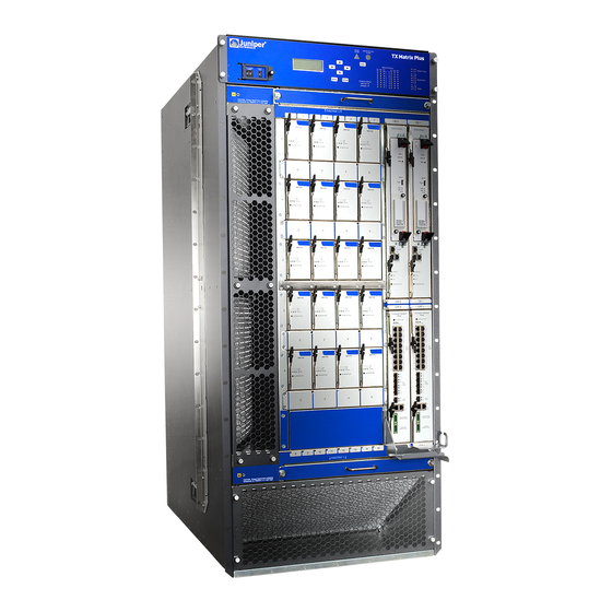
TX Matrix Plus Router
Quick Start
January 2015
Part Number: 530-062019
Revision 01
Contents
Copyright © 2015, Juniper Networks, Inc.
This document describes how to install the Juniper Networks TX Matrix Plus Router.
TX Matrix Plus Quick Start Description . . . . . . . . . . . . . . . . . . . . . . . . . . . . . . . . . . . 3
Step 1: Prepare the Site . . . . . . . . . . . . . . . . . . . . . . . . . . . . . . . . . . . . . . . . . . . . . . . 3
TX Matrix Plus Rack-Mounting Requirements . . . . . . . . . . . . . . . . . . . . . . . . . . 3
Tools Required to Install the TX Matrix Plus Router . . . . . . . . . . . . . . . . . . . . . 4
Step 2: Install the Mounting Hardware for a TX Matrix Plus Router . . . . . . . . . . . . . 4
Install the TX Matrix Plus Mounting Hardware for a Four-Post Rack . . . . . . . . 5
Install Cage Nuts, If Needed . . . . . . . . . . . . . . . . . . . . . . . . . . . . . . . . . . . . 5
Install the Four-Post Mounting Shelf and Rear Support Bracket . . . . . . . 6
Remove the Center-Mounting Brackets . . . . . . . . . . . . . . . . . . . . . . . . . . . 7
Assemble the Open-Frame Rack Mounting Shelf . . . . . . . . . . . . . . . . . . . 9
Install Cage Nuts, If Needed . . . . . . . . . . . . . . . . . . . . . . . . . . . . . . . . . . . . 9
Install the Open-Frame Rack Mounting Shelf . . . . . . . . . . . . . . . . . . . . . . 11
Step 3: Install the TX Matrix Plus Router Using a Mechanical Lift . . . . . . . . . . . . . 12
Remove TX Matrix Plus Components . . . . . . . . . . . . . . . . . . . . . . . . . . . . . . . . 12
Install the TX Matrix Plus Router Using a Lift . . . . . . . . . . . . . . . . . . . . . . . . . . 14
Reinstall TX Matrix Plus Components . . . . . . . . . . . . . . . . . . . . . . . . . . . . . . . 21
Device . . . . . . . . . . . . . . . . . . . . . . . . . . . . . . . . . . . . . . . . . . . . . . . . . . . . . . . . . 21
Step 5: Install the TX Matrix Plus Rear Cable Management System and Front
Cable Manager . . . . . . . . . . . . . . . . . . . . . . . . . . . . . . . . . . . . . . . . . . . . . . . . . 22
Step 6: Ground the TX Matrix Plus Router . . . . . . . . . . . . . . . . . . . . . . . . . . . . . . . . 23
Number . . . . . . . . . . . . . . . . . . . . . . . . . . . . . . . . . . . . . . . . . . . . . . . . . . . . . . . 23
Step 8: Connect Power to a Seven-Input 420-A Power Supply in a TX Matrix
Plus Router . . . . . . . . . . . . . . . . . . . . . . . . . . . . . . . . . . . . . . . . . . . . . . . . . . . . 24
1
Advertisement
Table of Contents

Related Manuals for Juniper TX Matrix Plus


Summary of Contents for Juniper TX Matrix Plus
-
Page 1: Table Of Contents
Step 6: Ground the TX Matrix Plus Router ....... . - Page 2 TX Matrix Plus Router Quick Start Step 9: Power On the TX Matrix Plus Router ......28 Step 10: Perform the Initial Software Configuration for the TX Matrix Plus Router .
-
Page 3: Tx Matrix Plus Quick Start Description
Tools Required to Install the TX Matrix Plus Router on page 4 TX Matrix Plus Rack-Mounting Requirements The TX Matrix Plus router can be installed in many types of racks. Follow these guidelines: The rack rails must be spaced widely enough to accommodate the TX Matrix Plus router chassis's external dimensions: 52.0 in. -
Page 4: Tools Required To Install The Tx Matrix Plus Router
For service personnel to remove and install hardware components, there must be adequate space at the front and back of the TX Matrix Plus router. Allow at least 30 in. (61.0 cm) both in front of and behind the TX Matrix Plus router. -
Page 5: Install The Tx Matrix Plus Mounting Hardware For A Four-Post Rack
0.25 in. (0.6 cm) 0.14 U The holes in the front-mounting flanges are spaced at 2 U (3.5 in. or 8.9 cm). Table 2: Mounting Hole Locations for Installing a TX Matrix Plus Chassis in a Four-Post Rack Hole Distance Above U Division 50.50 in. -
Page 6: Install The Four-Post Mounting Shelf And Rear Support Bracket
TX Matrix Plus Router Quick Start Table 2: Mounting Hole Locations for Installing a TX Matrix Plus Chassis in a Four-Post Rack (continued) Hole Distance Above U Division 43.50 in. (110.5 cm) 24.86 U 40.00 in. (101.6 cm) 22.86 U 36.5 in. -
Page 7: Remove The Center-Mounting Brackets
Several holes are provided on top of the shelf. Two holes on each side of the shelf will align with the holes in the rear support bracket. Tighten all the screws completely. Figure 2: Installing the TX Matrix Plus Mounting Hardware for a Four-Post Rack Four-post mounting shelf fits over the rear support bracket. -
Page 8: Install The Tx Matrix Plus Mounting Hardware For An Open-Frame Rack
TX Matrix Plus Router Quick Start Figure 3: TX Matrix Plus Center-Mounting Bracket Removal Center-mounting bracket Install the TX Matrix Plus Mounting Hardware for an Open-Frame Rack Assemble the Open-Frame Rack Mounting Shelf on page 9 Install Cage Nuts, If Needed on page 9 Install the Open-Frame Rack Mounting Shelf on page 11 Copyright ©... -
Page 9: Assemble The Open-Frame Rack Mounting Shelf
On the front side of both rack rails, insert cage nuts in the holes specified for mouting the chassis (see Table 4 on page 10). Table 3: Mounting Hole Locations for Installing a TX Matrix Plus Open-Frame Rack Shelf Hole Distance Above U Division Open-Frame MountingShelf 24.25 in. - Page 10 3.25 in. (3.8 cm) 1.86 U The holes in the center-mounting brackets are spaced at 2 U (3.5 in. or 8.9 cm). Table 4: Mounting Hole Locations for Installing a TX Matrix Plus Chassis in an Open-Frame Rack Hole Distance Above U Division Chassis 52.5 in.
-
Page 11: Install The Open-Frame Rack Mounting Shelf
Partially insert screws into the open holes in the flanges of the open-frame rack mounting shelf. Tighten all the screws completely. Figure 4: Installing the TX Matrix Plus Mounting Hardware for an Open-Frame Rack Insert screws in the holes specified in... -
Page 12: Step 3: Install The Tx Matrix Plus Router Using A Mechanical Lift
Install the TX Matrix Plus Router Using a Lift on page 14 Reinstall TX Matrix Plus Components on page 21 Remove TX Matrix Plus Components Before lifting the TX Matrix Plus router, you must remove the following components: Input power trays Power supplies... - Page 13 For detailed instructions on removing TX Matrix Plus router components, see the TX Matrix Plus Router Hardware Guide. To remove the components from the TX Matrix Plus router: Slide each component out of the chassis evenly so that it does not become stuck or damaged.
-
Page 14: Install The Tx Matrix Plus Router Using A Lift
Read the safety information in TX Matrix Plus Installation Safety Guidelines. Ensure that a mechanical lift and Phillips (+) screwdriver, number 2 are available for the installation. Because of the TX Matrix Plus router's size and weight—up to 925 lb (420 kg) depending on configuration—you must use a lift to install the TX Matrix Plus router. - Page 15 Install the TX Matrix Plus Router Using a Lift Have a qualified technician verify that the rack is strong enough to support the TX Matrix Plus router's weight and is adequately supported at the installation site. Ensure that the rack is in its permanent location and is secured to the building.
- Page 16 TX Matrix Plus Router Quick Start Figure 7: Loading the TX Matrix Plus Router onto the Lift Copyright © 2015, Juniper Networks, Inc.
- Page 17 Use these handles only to help position the TX Matrix Plus router. Using the lift, position the TX Matrix Plus router in front of the rack, centering it in front of the mounting shelf. Lift the chassis slightly above the surface of the mounting shelf, and position it as close as possible to the shelf.
- Page 18 TX Matrix Plus Router Quick Start Figure 8: Installing the TX Matrix Plus Router in an Open-Frame Rack Open frame rack Center-mounting bracket Copyright © 2015, Juniper Networks, Inc.
- Page 19 Install the TX Matrix Plus Router Using a Lift Figure 9: Installing the TX Matrix Plus Router in a Four-Post Rack Four-post rack Front-mounting flange The holes in the center-mounting brackets are spaced at 2 U (3.5 in. or 8.9 cm).
- Page 20 TX Matrix Plus Router Quick Start Table 6: Mounting Hole Locations for Installing a TX Matrix Plus Chassis in an Open-Frame Rack (continued) Hole Distance Above U Division Chassis 24.25 in. (61.6 cm) 13.86 U 20.75 in. (52.7 cm) 11.86 U 17.25 in.
-
Page 21: Reinstall Tx Matrix Plus Components
Slide each component into the chassis evenly so that it does not become stuck or damaged. Tighten the captive screws for each component. Step 4: Connect the TX Matrix Plus Router to a Management Console or Auxiliary Device Attach one or more management console or auxiliary devices to the Routing Engine ports... -
Page 22: Cable Manager
Auxiliary port Console port Figure 11: Console and Auxiliary Serial Port Connector Step 5: Install the TX Matrix Plus Rear Cable Management System and Front Cable Manager For instructions to install the rear cable management system and front cable manager, see the TX Matrix Plus Router Hardware Guide. -
Page 23: Step 6: Ground The Tx Matrix Plus Router
Step 6: Ground the TX Matrix Plus Router Step 6: Ground the TX Matrix Plus Router You ground the TX Matrix Plus router by attaching a grounding cable to the chassis. You must provide the grounding cable (the cable lugs are supplied with the router). -
Page 24: Plus Router
TX Matrix Plus Router Quick Start Step 8: Connect Power to a Seven-Input 420-A Power Supply in a TX Matrix Plus Router The input power tray weighs 3.7 lb (1.7 kg). To connect the DC source power cables to the seven-input 420-A power supply: Gather the following tools: 7/16-in. - Page 25 Step 8: Connect Power to a Seven-Input 420-A Power Supply in a TX Matrix Plus Router Remove the metal input power tray cover. Remove the power lug separator. Remove the cable restraint. Remove the nuts and washers from the power terminal studs on the lower row.
- Page 26 TX Matrix Plus Router Quick Start Figure 13: Connecting the Negative (–) DC Source Power Cable Lugs to an Input Power Tray Split washer Cable lug Terminal studs Power lug separator Input power tray Attach the power lug separator over the lower row of terminal studs.
- Page 27 Step 8: Connect Power to a Seven-Input 420-A Power Supply in a TX Matrix Plus Router Figure 14: Connecting the Positive (+) DC source Power Cable Lugs to an Input Power Tray in a TX Matrix Plus Router Power lug separator Input power tray Place the cable restraint over the DC power cables.
-
Page 28: Step 9: Power On The Tx Matrix Plus Router
Tighten captive screws. Input power tray Verify that the power cables are not touching or blocking access to TX Matrix Plus components, and that they do not drape where people could trip on them. Step 9: Power On the TX Matrix Plus Router... - Page 29 Step 9: Power On the TX Matrix Plus Router Verify that the LEDs on the power supply faceplate are lit steadily INPUT PRESENT green, indicating that the inputs are receiving power. WARNING: If any of the INPUT PRESENT LEDs are red, indicating that the power is reversed, switch off the customer site circuit breakers immediately.
-
Page 30: Router
Step 10: Perform the Initial Software Configuration for the TX Matrix Plus Router These procedures connect a TX Matrix Plus router to the network but do not enable it to forward traffic. For complete information about enabling the router to forward traffic, including examples, see the Junos OS configuration guides. -
Page 31: Configure System Attributes
[edit] root@# set system login user user-name class super-user Configure System Attributes Configure the name of the TX Matrix Plus router. If the name includes spaces, enclose the name in quotation marks (“ ”). [edit] root@# set system host-name host-name... -
Page 32: Commit The Configuration
TX Matrix Plus Router Quick Start [edit] root# set routing-options static route remote-subnet next-hop destination-IP retain no-readvertise Configure the telnet service at the [edit system services] hierarchy level. [edit] root# set system services telnet Commit the Configuration Display the configuration to verify that it is correct. -
Page 33: Step 11: Connect The Switching Plane Cables To The Tx Matrix Plus Router
Failure to use an ESD strap could result in damage to the router. Only trained and qualified personnel should install or replace the router. Perform only the procedures described in this Quick Start or the TX Matrix Plus Router Hardware Guide. Other services should be performed by authorized service personnel only. -
Page 34: Tx Matrix Plus Preventing Electrostatic Discharge Damage
TX Matrix Plus Router Quick Start Before installing the chassis, remove components as described in the TX Matrix Plus Router Hardware Guide. The router should be mounted at the bottom of the rack. If the rack is provided with stabilizing devices, install the stabilizers before mounting or servicing the router in the rack. - Page 35 TX Matrix Plus Preventing Electrostatic Discharge Damage Figure 17: ESD Point on Front of the TX Matrix Plus Router Craft interface panel Center-mounting bracket point TXP-F2 SIBs Fan tray 0 RE 0 RE 1 intake (2 air filters) CB 0...
- Page 36 TX Matrix Plus Router Quick Start Figure 18: ESD Point on Back of the TX Matrix Plus Router Air exhaust TXP-F13 SIBs ESD point Air exhaust Fan tray 2 Fan tray 4 Fan tray 5 Air exhaust Grounding points Fan tray 3...
-
Page 37: Tx Matrix Plus Compliance Statements For Nebs
TX Matrix Plus Compliance Statements for NEBs Figure 19: Placing a Component into an Electrostatic Bag TX Matrix Plus Compliance Statements for NEBs The equipment is suitable for installation as part of the Common Bonding Network (CBN). The equipment is suitable for installations in Network Telecommunication Facilities. -
Page 38: Israel
TX Matrix Plus Router Quick Start Israel Translation from Hebrew—Warning: This product is Class A. In residential environments, the product may cause radio interference, and in such a situation, the user may be required to take adequate measures. Japan Translation from Japanese—This is a Class A product. In a domestic environment this product may cause radio interference in which case the user may be required to take adequate measures. -
Page 39: Junos Os Documentation And Release Notes
7 days a week, 365 days a year. Self-Help Online Tools and Resources For quick and easy problem resolution, Juniper Networks has designed an online self-service portal called the Customer Support Center (CSC) that provides you with the following features: Find CSC offerings: http://www.juniper.net/customers/support/... -
Page 40: Opening A Case With Jtac
Juniper Networks, Junos, Steel-Belted Radius, NetScreen, and ScreenOS are registered trademarks of Juniper Networks, Inc. in the United States and other countries. The Juniper Networks Logo, the Junos logo, and JunosE are trademarks of Juniper Networks, Inc. All other trademarks, service marks, registered trademarks, or registered service marks are the property of their respective owners.