Toro Groundsmaster 4500-D Operator's Manual
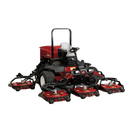
Ride-on lawnmover's traction unit
Hide thumbs
Also See for Groundsmaster 4500-D:
- Service manual (474 pages) ,
- Operator's manual (92 pages) ,
- Installation instructions manual (28 pages)
Table of Contents

Related Manuals for Toro Groundsmaster 4500-D


Summary of Contents for Toro Groundsmaster 4500-D
- Page 1 Form No. 3409-244 Rev C Groundsmaster ® 4500-D and 4700-D Traction Unit Model No. 30881—Serial No. 400000000 and Up Model No. 30882—Serial No. 400000000 and Up *3409-244* C Register at www.Toro.com. Original Instructions (EN)
- Page 2 Authorized Service specific Declaration of Conformity (DOC) sheet. Dealer or Toro Customer Service and have the model and serial numbers of your product ready. Figure 1 identifies the location of the model and serial numbers WARNING on the right front frame member of the product.
-
Page 3: Table Of Contents
Contents Maintenance ............48 Recommended Maintenance Schedule(s) ... 48 Daily Maintenance Checklist......49 Safety ............... 4 Service Interval Chart ........50 General Safety ........... 4 Pre-Maintenance Procedures ......51 Engine Emission Certification ......4 Pre-Maintenance Safety ........51 Safety and Instructional Decals ......5 Preparing the Machine for Maintenance.... -
Page 4: Safety
Safety Changing the Hydraulic Fluid ......71 Replacing the Hydraulic Filters ......71 Checking the Hydraulic Lines and This machine has been designed in accordance with Hoses............72 EN ISO 5395:2013 and ANSI B71.4-2012. Mower Deck Maintenance........73 Removing the Mower Decks ......73 Installing the Mower Decks ....... -
Page 5: Safety And Instructional Decals
Safety and Instructional Decals Safety decals and instructions are easily visible to the operator and are located near any area of potential danger. Replace any decal that is damaged or missing. decal93-6681 93-6681 1. Cutting/dismemberment hazard, fan—stay away from moving parts. decal106-6755 106-6755 1. - Page 6 decal117-4766 117-4766 1. Cutting/dismemberment hazard; fan—stay away from moving parts, keep all guards and shields in place. decal117-4763 117-4763 1. To engage the parking 2. To disengage the parking brake, secure the brake brake, disengage the pedals with the locking pin, locking pin and release the press the parking-brake pedals.
- Page 7 decal125-4604 125-4604 For Groundsmaster 4700 Only decal121-3884 121-3884 1. Raise left deck 3. Raise right deck 1. Engine—stop 3. Engine—start 2. Raise center decks 2. Engine—preheat decal121-3887 121-3887 1. Read the Operator’s Manual. decal125-4605 125-4605 1. Power seat—10 A 6. Power supplied—10 A 2.
- Page 8 decalbatterysymbols Battery Symbols Some or all of these symbols are on your battery 1. Explosion hazard 2. No fire, open flame, or smoking 3. Caustic liquid/chemical burn hazard 4. Wear eye protection. 5. Read the Operator's Manual. 6. Keep bystanders a safe distance away from the battery. 7.
- Page 9 decal121-3627 121-3627 1. Height-of-cut settings decal127-6447 127-6447 (Affix over Part No. 112-5297 for CE* for 4500 series machines) * This safety decal includes a slope warning required on the machine for compliance to the European Lawn Mower Safety Standard EN ISO 5395:2013. The conservative maximum slope angles indicated for operation of this machine are prescribed by and required by this standard.
- Page 10 decal127-6448 127-6448 (Affix over Part No. 112-5297 for CE* for 4700 series machines) * This safety decal includes a slope warning required on the machine for compliance to the European Lawn Mower Safety Standard EN ISO 5395:2013. The conservative maximum slope angles indicated for operation of this machine are prescribed by and required by this standard. This machine complies with the industry standard stability test in the static lateral and longitudinal tests with the maximum recommended slope indicated on the decal.
-
Page 11: Setup
Setup Loose Parts Use the chart below to verify that all parts have been shipped. Procedure Description Qty. Replace the warning decal (CE Warning decal machines only). Hood-latch bracket Rivet Install the hood latch (CE machines Washer only). Screw (1/4 x 2 inches) Locknut (1/4 inch) –... - Page 12 Installing the Hood Latch (CE Machines Only) Parts needed for this procedure: G012629 Hood-latch bracket Rivet g012629 Figure 4 Washer 1. CE lock bracket 2. Bolt and nut Screw (1/4 x 2 inches) Locknut (1/4 inch) 4. Align the washers with the holes on the inside of the hood.
-
Page 13: Adjusting The Roller Scraper (Optional)
Adjusting the Roller Scraper (Optional) G012631 No Parts Required g012631 Figure 6 Procedure 1. Bolt 3. Arm of hood-latch bracket 2. Nut The optional rear roller scraper is designed to work best when there is an even gap of 0.5 to 1 mm (0.020 to 0.040 inch) between the scraper and roller. -
Page 14: Installing The Mulching Baffle (Optional)
Installing the Mulching Preparing the Machine Baffle (Optional) No Parts Required No Parts Required Checking the Tire Pressure Procedure Check the tire pressure before use; refer to Checking the Tire Pressure (page 27). 1. Thoroughly clean debris from the mounting holes Important: on the rear wall and left wall of the chamber. -
Page 15: Product Overview
Product Overview down on the right brake pedal while engaging the toe pedal. To release the parking brake, press 1 of the brake pedals until the parking brake latch retracts. Controls Tilt-Steering Pedal Press the tilt-steering pedal to tilt the steering wheel to the desired position, then release the pedal to lock the adjustment (Figure... - Page 16 Power Point Hold down the switch to automatically move to High or Low idle, depending on which end of the switch Use the power point (Figure 12) to power optional 12 you press. V electrical accessories. PTO Switch The PTO switch has 2 positions: O ) and START ).
- Page 17 Using the InfoCenter LCD Display The InfoCenter LCD display shows information about your machine, such as the operating status, various diagnostics and other information about the machine (Figure 14). There is a splash screen and main information screen of the InfoCenter. You can switch between the splash screen and main information screen at any time by pressing any of the InfoCenter buttons and then selecting the appropriate directional...
- Page 18 InfoCenter Icon Description InfoCenter Icon Description (cont'd.) SERVICE DUE Indicates when scheduled service should be performed The cruise control is on. The status of the engine rpm. Stop the engine. Info icon Engine Maximum traction speed setting Fast Key switch Cutting units are lowering.
- Page 19 InfoCenter Icon Description (cont'd.) Symbols are often combined to form sentences. Some examples are shown below Operator should put machine in neutral. Engine start is denied. Engine shutdown. Engine coolant is too hot. Hydraulic fluid is too hot. DPF ash accumulation notification. Refer to Servicing the Diesel Particulate Filter (DPF) in the maintenance section for details.
- Page 20 Lists the software revision of experienced. the master controller. Diagnostics Menu Item Description Left Deck Refer to the Service Manual or your Toro Distributor for more Center Deck information on the Engine Run menu and the information Right Deck contained there. Traction HI/LO Range...
- Page 21 The factory default PIN code for you machine is either 0000 or 1234. If you changed the PIN code and forgot the code, contact your Authorized Toro Distributor for assistance. 1. From the M , use the center button to...
- Page 22 Viewing and Changing the Setting the Counterbalance Protected Menu Settings 1. In the Settings Menu, scroll down to Counter Balance and press the right button. 1. In the Protected Menu, scroll down to Protect Settings. 2. Press the right button to switch between Low, Med, and High.
-
Page 23: Specifications
Specifications g198614 Figure 17... -
Page 24: Machine Specifications
A selection of Toro approved attachments and accessories is available for use with the machine to enhance and expand its capabilities. Contact your Authorized Service Dealer or Distributor or go to www.Toro.com for a list of all approved attachments and accessories. -
Page 25: Before Operation
Checking the Engine-Oil Operation Level Note: Determine the left and right sides of the machine from the normal operating position. Before you start the engine and use the machine, check the oil level in the engine crankcase; refer to Checking the Engine-Oil Level (page 55). -
Page 26: Filling The Fuel Tank
• Do not use fuel additives. • Contact your Authorized Toro Distributor if you wish for more information on biodiesel. Petroleum Diesel Cetane rating: 45 or higher Sulfur content: Ultra-low sulfur (<15 ppm) -
Page 27: Checking The Tire Pressure
Adding Fuel Checking the Tire Pressure Service Interval: Before each use or daily The correct air pressure in the tires is 138 kPa (20 psi). Important: Maintain the recommended pressure in all tires to ensure a good quality of cut and proper machine performance. -
Page 28: Checking The Torque Of The Wheel-Lug Nuts
Checking the Torque of the Adjusting the Rollover Protection System (ROPS) Wheel-Lug Nuts Service Interval: After the first hour WARNING After the first 10 hours To avoid injury or death from rollover: keep Every 200 hours the roll bar in the raised locked position and use the seat belt. -
Page 29: Adjusting The Height Of Cut
Lowering the Roll Bar Adjusting the Height of Cut Important: Lower the roll bar only when Important: The mower decks often cut necessary. approximately 6 mm (1/4 inch) lower than a reel cutting unit with the same bench setting. It may Important: Ensure that the seat is secured with be necessary to set the mower deck’s bench 6 mm... -
Page 30: Checking The Interlock Switches
Checking the Interlock 7. Install the bolt finger-tight. 8. Repeat steps through for each side Switches adjustment. Service Interval: Before each use or daily 9. Torque all 3 bolts to 41 N∙m (30 ft-lb). Always tighten the front bolt first. CAUTION Note: Adjustments of more than 3.8 cm (1-1/2... -
Page 31: Checking The Blade-Stopping Time
If this time is • It has more lift and a higher discharge velocity. greater than 7 seconds, adjust the braking valve. Call your Toro Distributor for assistance in making this • Sparse or limp turf is picked up significantly at adjustment. - Page 32 Pros Even discharge at lower More lift and higher May improve dispersion Reduces roller buildup height of cut; cleaner discharge velocity; and appearance in in certain applications look around bunkers and sparse or limp turf is certain grass cutting fairways; lower power applications;...
-
Page 33: During Operation
• Use accessories, attachments, and replacement • Wear appropriate clothing, including eye parts approved by The Toro® Company only. protection; slip-resistant, substantial foot protection; and hearing protection. Tie back long Rollover Protection System hair and do not wear jewelry. -
Page 34: Starting The Engine
• Important: Operate the machine at a lower speed when you Shut off the engine and allow the are on a slope. engine to cool before you check for oil leaks, loose parts, or other malfunctions. • If you feel uneasy operating the machine on a slope, do not do it. -
Page 35: Diesel Particulate Filter Regeneration
Diesel Particulate Filter Important: Minimize the amount of time that you idle the engine or operate the engine at low-engine Regeneration speed to help reduce the accumulation of soot in the soot filter. The diesel particulate filter (DPF) is part of the exhaust system. - Page 36 DPF Ash Accumulation • When enough ash accumulates, the engine computer sends information to the InfoCenter in • The lighter ash is discharged through the exhaust the form of a system advisory or an engine fault to system; the heavier ash collects in the soot filter. indicate the accumulation of ash in the DPF.
- Page 37 Types of Diesel Particulate Filter Regeneration Types of diesel particulate filter regeneration that are performed while the machine is operating: Type of Regeneration Conditions for DPF regeneration DPF description of operation Passive Occurs during normal operation of the machine at The InfoCenter does not display an icon indicating high-engine speed or high-engine load passive regeneration.
- Page 38 DPF is already in need of a parked When the recovery-regeneration icon regeneration displayed in the InfoCenter, a recovery regeneration is requested. Contact your Authorized Toro Distributor to have a service technician perform the recovery regeneration. • A recovery regeneration requires up to 4 hours to complete.
- Page 39 Reset Regeneration Parked Regeneration g214713 g214711 Figure 34 Figure 33 Parked-regeneration request icon Assist/reset-regeneration icon • The parked-regeneration requested icon displays • The assist/reset-regeneration icon displays in the in the InfoCenter (Figure 34). InfoCenter (Figure 33). • If a parked regeneration is needed, the InfoCenter •...
- Page 40 6. Engage the parking brake. 7. Set the throttle to the low I position. Performing a Parked Regeneration Note: For instructions on unlocking protected menus, refer to Accessing Protected Menus (page 21). 1. Access the protected menu and unlock the protected settings submenu (Figure 36);...
- Page 41 g211986 g212405 Figure 40 Figure 42 6. Move the throttle control to and press LOW IDLE B. The “Waiting on ” message displays the center button (Figure 41). (Figure 43). g212372 g212406 Figure 41 Figure 43 7. The following messages display as the parked C.
- Page 42 The engine is cold—wait. The engine is warm—wait. The engine hot—regeneration in progress (percent complete). 9. The parked regeneration is complete when the “Regen Complete” message displays in the InfoCenter. Press the left button to exit to the home screen (Figure 46).
-
Page 43: Understanding The Operating Characteristics Of The Machine
With Toro Smart Power™, the operator does not have to listen to the engine speed in heavy conditions. Smart Power prevents bogging down in heavy turf by automatically controlling the machine speed and optimizing cutting performance. -
Page 44: Using Cruise Control
Using Cruise Control Operating Tips The cruise-control switch locks in the pedal position to Operating the Machine maintain the desired ground speed. Pressing the rear of the switch turns the cruise control off, the middle • Start the engine. If the A function is position of the switch enables the cruise-control turned off, run it at H... - Page 45 Resolving After-Cut Appearance Checking the Condition of the Mower Deck Reference the After-cut Appearance Troubleshooting Guide available at www.Toro.com. Ensure that the cutting chambers are in good condition. Straighten any bends in the chamber components to ensure correct blade tip/chamber Using Proper Mowing Techniques clearance.
-
Page 46: After Operation
After Operation After Operation Safety • Clean grass and debris from the cutting units, mufflers, and engine compartment to help prevent fires. Clean up oil or fuel spills. • If the cutting units are in the transport position, use the positive mechanical lock (if available) before you leave the machine unattended. -
Page 47: Locating The Tie-Down Points
Locating the Tie-Down Points Note: Use properly-rated DOT-approved straps in 4 corners to tie down the machine. • On each side of the frame by the operator’s platform • On the rear bumper g208989 Figure 51 g036665 Figure 52... -
Page 48: Maintenance
Important: Refer to your engine owner’s manual for additional maintenance procedures. Note: Download a free copy of the electrical or hydraulic schematic by visiting www.Toro.com and searching for your machine from the Manuals link on the home page. Note: Determine the left and right sides of the machine from the normal operating position. -
Page 49: Daily Maintenance Checklist
Maintenance Service Maintenance Procedure Interval • Disassemble, clean, and assemble the soot filter of the DPF. or clean the soot filter if engine faults 3720 3720 0, or 3720 16 display Every 6,000 hours in the InfoCenter. • Drain and clean the fuel tank. •... -
Page 50: Service Interval Chart
For the week of: Maintenance Check Item Monday Tuesday Wednesday Thursday Friday Saturday Sunday Lubricate all the grease fittings. Touch up any damaged paint. Check the glow plug and injector nozzles if starting is hard, there is excess smoke, or rough running is noted. Immediately after every washing, regardless of the interval listed. -
Page 51: Pre-Maintenance Procedures
Pre-Maintenance Important: Do not support the machine at the wheel-drive motors. Keep the lifting equipment Procedures clear of hydraulic tubing and hoses. Pre-Maintenance Safety • Before adjusting, cleaning, repairing, or leaving the machine, do the following: – Park the machine on a level surface. –... -
Page 52: Opening The Hood
Opening the Hood Accessing the Hydraulic Lift Compartment Tilt the hood to access the chassis as shown in Figure Tilt the seat to access the hydraulic lift compartment as shown in Figure g036674 g036706 Figure 56 Figure 57... -
Page 53: Lubrication
Lubrication • Steering-cylinder ball joints (2) as shown in Figure Greasing the Bearings and Bushings Service Interval: Every 50 hours (And after every washing). Grease specification: No. 2 lithium grease The grease fitting locations and quantities are as follows: • Brake-shaft pivot bearings (5) as shown in Figure g009706... -
Page 54: Engine Maintenance
Engine Maintenance • Cutting-unit spindle-shaft bearings (2 per mower deck) as shown in Figure 62 Note: You can use either fitting, whichever is Engine Safety more accessible. Pump grease into the fitting until a small amount appears at the bottom of the •... -
Page 55: Servicing The Engine Oil
Preferred oil: SAE 15W-40 (above 0°F) • Alternate oil: SAE 10W-30 or 5W-30 (all temperatures) Toro Premium Engine Oil is available from your Authorized Toro Distributor in either 15W-40 or 10W-30 viscosity grades. See the parts catalog for part numbers. -
Page 56: Servicing The Diesel-Oxidation Catalyst (Doc) And The Soot Filter
Changing the Engine Oil and Filter If the engine oil level is above the Full mark, change the engine oil. Service Interval: After the first 50 hours The best time to check the engine oil is when the Every 250 hours engine is cool before it has been started for the day. -
Page 57: Fuel System Maintenance
Use clean the soot filter of the DPF. fuel to flush out the tank. 2. Refer to your Authorized Toro Distributor for diesel-oxidation catalyst and the soot filter Inspecting the Fuel Lines replacement parts or service. -
Page 58: Servicing The Water Separator
Servicing the Water Servicing the Fuel Filter Separator Service Interval: Every 400 hours 1. Clean the area around the fuel-filter head Service Interval: Before each use or daily—Drain (Figure 72). water or other contaminants from the fuel filter/water separator. Every 400 hours—Replace the fuel-filter canister. -
Page 59: Cleaning The Fuel-Pickup Tube Screen
Cleaning the Fuel-Pickup Priming the Fuel System Tube Screen Prime the fuel system before starting the engine for the first time, after running out of fuel, or after fuel The fuel-pickup tube, located inside the fuel tank, is system maintenance (e.g. draining the filter/water equipped with a screen to help prevent debris from separator, replacing a fuel hose). -
Page 60: Bleeding Air From The Injectors
Rinse with clear water. Coat the battery posts and cable connectors with Grafo 112X (skin-over) grease (Toro Part No. 505-47) or petroleum jelly to prevent corrosion. Charging and Connecting the Battery 1. - Page 61 WARNING Incorrect battery cable routing could damage the machine and cables, causing sparks. Sparks can cause the battery gasses to explode, resulting in personal injury. • Always disconnect the negative (black) battery cable before disconnecting the positive (red) cable. • Always connect the positive (red) battery cable before connecting the negative (black) cable.
-
Page 62: Locating The Fuses
WARNING Charging the battery produces gasses that can explode. Never smoke near the battery and keep sparks and flames away from battery. 5. When the battery is charged, disconnect the charger from the power outlet and battery posts. 6. Install the positive cable (red) to the positive (+) terminal and the negative cable (black) to the negative (-) terminal of the battery (Figure... -
Page 63: Drive System Maintenance
5. Repeat steps through on the opposite movement. planetary gear assembly. g028798 Figure 80 1. Front drive wheels 4. Repeat step for the other drive wheel. 5. If either wheel moves, contact your Toro Distributor to have the planetary drive rebuilt. -
Page 64: Changing The Planetary-Gear-Drive Oil
Changing the 6. Through the open hole, slowly fill the planetary with 0.65 L (22 fl oz) of high quality SAE Planetary-Gear-Drive Oil 85W-140 wt gear lube. Important: If the planetary fills before the Service Interval: After the first 200 hours 0.65 L (22 fl oz) of oil is added, wait 1 hour Every 800 hours or yearly, whichever comes or install the plug and move the machine... -
Page 65: Changing The Rear-Axle Lubricant
Note: If the level is low, remove the fill plug and lube or until the lubricant is up to the bottom of add enough lubricant to bring the level up to the the hole. bottom of the check-plug holes. 7. Install the check plug. Checking the Rear-Axle-Gearbox Lubricant... -
Page 66: Checking The Rear Wheel Toe-In
Checking the Rear Wheel 6. Install the ball joint in the axle-case support, tighten the nut finger-tight, and measure the Toe-In toe-in. 7. Repeat procedure if necessary. Service Interval: Every 800 hours/Yearly (whichever comes first) 8. Tighten the nut and install a new cotter pin when the adjustment is correct. -
Page 67: Cooling System Maintenance
Cooling System Maintenance Cooling System Safety • Swallowing engine coolant can cause poisoning; keep out of reach from children and pets. • Discharge of hot, pressurized coolant or touching a hot radiator and surrounding parts can cause severe burns. – Always allow the engine to cool at least 15 minutes before removing the radiator cap. -
Page 68: Brake Maintenance
Brake Maintenance Adjusting the Service Brakes Adjust the service brakes when there is more than 25 mm (1 inch) of free travel of the brake pedal, or when the brakes do not work effectively. Free travel is the distance the brake pedal moves before you feel braking resistance. -
Page 69: Belt Maintenance
Toro Premium All Season Hydraulic Fluid (Available in 19 L (5 US gallons) pails or 208 L (55 US gallons) drums. See the Parts Catalog or your Toro Distributor for part numbers). Alternative fluids: If the Toro fluid is not available,... - Page 70 Mobil EAL EnviroSyn 46H is the only synthetic biodegradable fluid approved by Toro. This fluid is compatible with the elastomers used in Toro hydraulic systems and is suitable for a wide-range of temperature conditions. This fluid is compatible with conventional mineral oils, but for...
-
Page 71: Changing The Hydraulic Fluid
Service Interval: After the first 200 hours Service Interval: Every 800 hours Every 800 hours If the fluid becomes contaminated, contact your Toro Distributor because the system must be flushed. Use Toro replacement filters Part No. 94-2621 for Contaminated fluid looks milky or black when the rear (mower decks) of the machine and Part No. -
Page 72: Checking The Hydraulic Lines And Hoses
Checking the Hydraulic Lines and Hoses Service Interval: Before each use or daily Inspect the hydraulic lines and hoses daily for leaks, kinked lines, loose mounting supports, wear, loose fittings, weather deterioration, and chemical deterioration. Make all necessary repairs before operating the machine. -
Page 73: Mower Deck Maintenance
Mower Deck Installing the Mower Decks 1. Move the mower deck into position in front of Maintenance the machine. 2. Slide the deck carrier frame onto the lift-arm-pivot Removing the Mower Decks (Figure 99). Secure the deck to the pin with the lynch pin (for Groundsmaster 4500 machines) or retaining nut (for Groundsmaster 1. -
Page 74: Blade Maintenance
Blade Maintenance 3. Press the second bearing into the roller housing (Figure 100). Pressing equally on the inner and outer race until the inner race comes in contact Blade Safety with the spacer. 4. Install the roller assembly into the deck frame. A worn or damaged blade can break, and a piece of the blade could be thrown toward you or bystanders, 5. -
Page 75: Removing And Installing The Mower Blade(S)
Adjusting the Blade Plane Replace the blade if it hits a solid object, is out of balance, or if it is bent. Always use genuine Toro Start with the front adjustment (change 1 bracket at a replacement blades to ensure safety and optimum time). -
Page 76: Inspecting And Sharpening The Mower Blade(S)
Inspecting and Sharpening the Mower Blade(s) Two areas must be considered when checking and servicing the mower blade—the sail and the cutting edge. Both cutting edges and the sail, which is the turned-up portion opposite of the cutting edge, contribute to a good quality of cut. The sail is important because it lifts the grass up straight, thereby producing an even cut. -
Page 77: Storage
B. Clean the battery, terminals, and posts with a wire brush and baking soda solution. C. Coat the cable terminals and battery posts with Grafo 112X skin-over grease (Toro Part No. 505-47) or petroleum jelly to prevent corrosion. D. Slowly recharge the battery every 60 days for 24 hours to prevent lead sulfation of the battery. - Page 78 10. Check the anti freeze protection and add a 50/50 solution of water and ethylene glycol anti-freeze as needed for the expected minimum temperature in your area. Mower Deck If the mower decks are separated from the traction unit for any length of time, install a spindle plug in the top of the spindles to protect the spindles from dust and water.
- Page 79 The Way Toro Uses Information Toro may use your personal information to process warranty claims, to contact you in the event of a product recall and for any other purpose which we tell you about. Toro may share your information with Toro's affiliates, dealers or other business partners in connection with any of these activities. We will not sell your personal information to any other company.
- Page 80 Countries Other than the United States or Canada Customers who have purchased Toro products exported from the United States or Canada should contact their Toro Distributor (Dealer) to obtain guarantee policies for your country, province, or state. If for any reason you are dissatisfied with your Distributor's service or have difficulty obtaining guarantee information, contact the Toro importer.