Extron electronics DXP HD 4K PLUS Series User Manual
4k hdmi switchers
Hide thumbs
Also See for DXP HD 4K PLUS Series:
- User manual (54 pages) ,
- Setup manual (17 pages) ,
- User manual (48 pages)

Related Manuals for Extron electronics DXP HD 4K PLUS Series


Summary of Contents for Extron electronics DXP HD 4K PLUS Series
- Page 1 User Guide Matrix Switchers DXP HD 4K PLUS Series 4K HDMI Switchers 68-2939-01 Rev. F 03 20...
- Page 2 Safety Instructions Safety Instructions • English Istruzioni di sicurezza • Italiano AVVERTENZA: Il simbolo, , se usato sul prodotto, serve ad This symbol, , when used on the product, is intended to WARNING avvertire l’utente della presenza di tensione non isolata pericolosa alert the user of the presence of uninsulated dangerous voltage within the all’interno del contenitore del prodotto che può...
- Page 3 Copyright © 2018-2020 Extron Electronics. All rights reserved. www.extron.com Trademarks All trademarks mentioned in this guide are the properties of their respective owners. The following registered trademarks ( ® ), registered service marks ( ), and trademarks ( ) are the property of RGB Systems, Inc. or Extron Electronics (see the current list of trademarks on the...
- Page 4 FCC Class A Notice This equipment has been tested and found to comply with the limits for a Class A digital device, pursuant to part 15 of the FCC rules. The Class A limits provide reasonable protection against harmful interference when the equipment is operated in a commercial environment.
- Page 5 Conventions Used in this Guide Notifications The following notifications are used in this guide: WARNING: Potential risk of severe injury or death. AVERTISSEMENT : Risque potentiel de blessure grave ou de mort. CAUTION: Risk of minor personal injury. ATTENTION : Risque de blessure mineure.
-
Page 7: Table Of Contents
Power Save Modes ........30 Selecting the Remote RS-232 Port Baud About this Guide ..........1 Rate ............30 About the DXP HD 4K PLUS Series Matrix Front Panel Functions — DXP 42 ..... 31 Switchers ............1 Creating Ties ..........31 Features ............. - Page 8 What is an IP Address?....... 104 Choosing IP Addresses ......105 Subnet Mask ..........105 Pinging for the IP Address ......106 Connecting as a Telnet Client ...... 107 Subnetting, a Primer ........109 DXP HD 4K PLUS Series • Contents viii...
-
Page 9: Introduction
This guide contains installation, configuration, and operating information for the DXP HD 4K PLUS Series matrix switchers. In this guide, the terms “DXP,” “switcher,” and “DXP matrix switcher” are used interchangeably to refer to any or all DXP HD 4K PLUS Series models. About the DXP HD 4K PLUS Series Matrix Switchers The DXP HD 4K PLUS Series are high performance HDMI matrix switchers for computer and video resolutions up to 4K @ 60 Hz. -
Page 10: Features
HDMI input source. • S/PDIF audio output (DXP 44, 84, and 88 only) — The DXP HD 4K PLUS Series includes two S/PDIF outputs for 2-channel LPCM audio or encoded standard definition bitstream audio for Dolby or DTS multi-channel surround sound. -
Page 11: Edid Minder
All inputs support unique EDID emulation, HDCP, and HDCP Authorization enabling or disabling. Managing EDID You can manage EDID files using PCS (see the DXP HD 4K PLUS Series Help file). You EDID Commands can also select and import EDID files using SIS commands (see the page 50). -
Page 12: Factory Loaded Edid
EDID from output 5 Output 6 Automatically populated with sink EDID from output 6 Output 7 Automatically populated with sink EDID from output 7 Output 8 Automatically populated with sink EDID from output 8 DXP HD 4K PLUS Series • Introduction... - Page 13 EXN_HDMI_1080p60_2Ch.bin Manually populated via PCS Input 4 (store) EXN_HDMI_1080p60_2Ch.bin Manually populated via PCS Output 1 Automatically populated with sink EDID from output 1 Output 2 Automatically populated with sink EDID from output 2 DXP HD 4K PLUS Series • Introduction...
-
Page 14: Application Diagrams
Table Mic IP Link Pro Ethernet Control Processor Ethernet Extron TLP Pro 1025T 10" Tabletop TouchLink HDMI Videoconferencing PC Pro Touchpanel Capture Figure 2. Application Diagram for a DXP 42 HD 4K PLUS DXP HD 4K PLUS Series • Introduction... -
Page 15: Installation
Installation This section describes the rear panels of the DXP HD 4K PLUS Series matrix switchers and provides instructions for cabling. It covers the following topics: • Rear Panels • Connecting to the LAN Port Connecting to the Remote RS-232 Port •... -
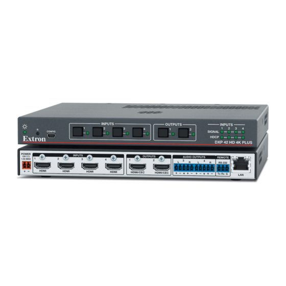
Page 16: Dxp 42 Rear Panel
RS-232 control (see Connecting to the Remote RS-232 Port on page 12 for more information). Connect the 9-pin connector end of the RS-232 cable to the serial port of your computer or control system. DXP HD 4K PLUS Series • Installation... - Page 17 Pour l’audio asymétrique, connectez les manchons au contact au sol. Ne PAS connecter les manchons aux contacts négatifs (–). NOTE: The length of exposed wires is important. The ideal length is 3/16 inch (5 mm). DXP HD 4K PLUS Series • Installation...
-
Page 18: Connecting To The Lan Port
328 feet (100 m). NOTES: Do not use standard telephone cables. Telephone cables do not support Ethernet • or Fast Ethernet. • Do not stretch or bend the cables, as this can cause transmission errors. DXP HD 4K PLUS Series • Installation... - Page 19 The Ethernet cable must be properly terminated for your application as either a crossover or a straight-through cable. Crossover cable — Direct connection between the computer and the DXP switcher • • Patch (straight-through) cable — Connection of the DXP to a network via a network switch DXP HD 4K PLUS Series • Installation...
-
Page 20: Connecting To The Remote Rs-232 Port
NOTES: • The switcher operates at 300 to 115200 baud. The default is 9600. • Selecting the Remote RS-232 Port Baud Rate on page 30 to configure this port using the front panel buttons. DXP HD 4K PLUS Series • Installation... -
Page 21: Securing The Hdmi Connectors Using The Lockit Hdmi Cable Lacing Bracket
Loosely place the included tie wrap around the HDMI connectors and the bracket ( While holding the connector securely against the lacing bracket, tighten the tie wrap, then remove any excess length ( DXP HD 4K PLUS Series • Installation... -
Page 22: Operation
The EDID is then made available to be assigned to any input. This feature is available only through PCS (see the DXP HD 4K PLUS Series Help File). •... -
Page 23: Front Panel Controls And Indicators
DXP HD 4K PLUS 88 Series Front Panel Figure 8 shows a DXP 88 HD 4K front panel. The DXP 44 and 84 front panels are identical to this one except for the product names. DXP HD 4K PLUS Series • Operation... -
Page 24: Dxp 42 Front Panel
Primary: Select an input. • Secondary: View ties. Output buttons — The output buttons have the following functions: DXP 44, 84, and 88 • Primary: • Select outputs. • Identify the selected outputs. DXP HD 4K PLUS Series • Operation... - Page 25 Cancel operations or selections in progress and resets the front panel button indicators. NOTE: The Esc button does not reset the current configuration or any presets. • Indicate that the escape function has been activated (blinks once). DXP HD 4K PLUS Series • Operation...
- Page 26 ) is being pressed and held, this LED blinks every 3 seconds to indicate the level of reset that is initiated if the button is released at that point (see Resetting on page 32 for more information). DXP HD 4K PLUS Series • Operation...
-
Page 27: Powering On
DXP 42 — All the front panel button LEDs blink. After the power up sequence is completed, the button LEDs turn off. The Signal and HDCP LEDs light according to the current state of each input. DXP HD 4K PLUS Series • Operation... -
Page 28: Front Panel Functions - Dxp 44, 84, And 88
LEDs for outputs that were already tied to the input light the appropriate color steadily. Outputs that are already tied can be left on, along with new blinking selections, or toggled off by pressing the associated output button. DXP HD 4K PLUS Series • Operation... - Page 29 Lights red when audio is selected. Figure 11. Selecting Audio or Video using the I/O Button Press the desired input button. The LED lights to indicate the selection. Figure 12. Selecting an Input for the Tie DXP HD 4K PLUS Series • Operation...
- Page 30 Selecting an Input with Ties (Video) • If only audio is selected, the LED for the selected input button lights red to indicate that audio outputs (output 2 only) can be tied to or untied from this input. DXP HD 4K PLUS Series • Operation...
- Page 31 The LEDs for any outputs already tied to the selected input The LED lights to indicate whether audio or light to indicate the existing video ties (audio in this example). video was selected for the input. INPUTS OUTPUTS Figure 18. Selecting an Input DXP HD 4K PLUS Series • Operation...
- Page 32 If you press an output button while an input is selected for viewing, the • output LED blinks to indicate a pending tie. Press Esc to cancel the tie or Enter to add the tie to the selected input. DXP HD 4K PLUS Series • Operation...
-
Page 33: Saving And Recalling Presets
Preset Preset Preset Preset Preset Preset Figure 22. Preset Locations NOTE: Before attempting to save or recall a preset, ensure that the unit is not in Power save mode 2 (see page 30). DXP HD 4K PLUS Series • Operation... -
Page 34: Muting And Unmuting Outputs From The Front Panel
Locking and Unlocking the Front Panel (Executive Modes) page 28). • To enable changes to the mute settings, set the lock mode to 0 and ensure that the unit is not in Power save mode 2 (see page 30). DXP HD 4K PLUS Series • Operation... - Page 35 For example, after viewing the audio mute status of an output and before it times out, press the I/O button again to view the video status of the same output. To exit the view mode, press Esc or wait for the indicators to time out. DXP HD 4K PLUS Series • Operation...
-
Page 36: Locking And Unlocking The Front Panel (Executive Modes)
The Video and Audio LEDs blink twice if the DXP is now in lock mode 0. Press and hold simultaneously. VIDEO ENTER 3 seconds AUDIO VIDEO The LEDs blink twice. AUDIO Release the buttons. Figure 27. Switching between Front Panel Lock Modes 0 and 2 DXP HD 4K PLUS Series • Operation... - Page 37 You must first place the switcher in lock mode 2, then toggle it to mode 0 (see Selecting Front Panel Lock Mode 2 or Toggling between Lock Modes 2 and 0 page 28). DXP HD 4K PLUS Series • Operation...
-
Page 38: Power Save Modes
Press and release an output button to exit the Serial Port Configuration mode. To change a value, press and release the Control button that relates to the desired value. The LEDs for the selected buttons blink and the other LEDs remain lit. DXP HD 4K PLUS Series • Operation... -
Page 39: Front Panel Functions - Dxp 42
Press the button for the input to be untied. The LEDs for the tied outputs light. Press the output button to be untied. The output button LED turns off, indicating that the tie is broken. DXP HD 4K PLUS Series • Operation... -
Page 40: Viewing Ties - Dxp 42
Reset Commands on page 57) • PCS (see the DXP HD 4K PLUS Series Help File) NOTE: Entering the E ZQQQ } SIS command or performing a mode 5 reset via the rear panel Reset button (see the Reset Modes Summary on page 34) removes... -
Page 41: Resetting Using The Front Or Rear Panel Reset Button
Analysez minutieusement les différents modes de réinitialisation voir tableau page • suivante. Appliquer le mauvais mode de réinitialisation peut causer une perte inattendue de la programmation de la mémoire flash, une reconfiguration des ports ou une réinitialisation du sélecteur. DXP HD 4K PLUS Series • Operation... - Page 42 1 to mode 5. • There is no reset mode 2 for DXP HD 4K PLUS Series. If you attempt to initiate it, the Power and Reset LED blinks 3 times but no reset is performed. Reset Modes Summary...
-
Page 43: Troubleshooting
Ensure that an active input is selected for output on the switcher. Ensure that the proper signal format is supplied. Check the cabling and make corrections as necessary. Call the Extron S3 Sales & Technical Support Hotline if necessary. DXP HD 4K PLUS Series • Operation... -
Page 44: Configuration Worksheets
Fill in the preset number and use colors, dashes, and so forth, to make connecting lines. Figure 34. Worksheet Example 1: System Equipment Inputs include media players, a PC, a laptop, editing stations, and 4K cameras. Output devices include various 4K monitors. DXP HD 4K PLUS Series • Operation... -
Page 45: Worksheet Example 2: Daily Configuration
Output Destinations Weekly status mtg Preset # Title: Video ties: Fill in the preset number and use colors, dashes, and so forth, to make connecting lines. Figure 36. Worksheet Example 3: Test Configuration DXP HD 4K PLUS Series • Operation... -
Page 46: Worksheet Form
Fill in the preset number and use colors, or dashes, and so on, to make connecting lines. Disregard or cross out the input and output boxes that do not apply to your switcher. DXP HD 4K PLUS Configuration Worksheet DXP HD 4K PLUS Series • Operation... -
Page 47: Sis Configuration And Control
SIS Configuration and Control The DXP HD 4K PLUS Series can be configured and controlled with Extron Simple Instruction Set commands. This section describes the communication between a connected host computer or other control device (such as a control system) and the device. Topics... -
Page 48: Device-Initiated Messages
(for example, if the display is disconnected from the unit). is the output number. Reconfig • The switcher sends this response upon any change of input frequency on the currently selected input or inputs. DXP HD 4K PLUS Series • SIS Configuration and Control... -
Page 49: Error Responses
Number of Connections A DXP HD 4K PLUS Series switcher can have up to 200 simultaneous TCP connections, including all http and Telnet connections. When the connection limit is reached, the switcher accepts no new connections until some have been closed. No error message or indication is given that the connection limit has been reached. -
Page 50: Sis Overview
RS-232 serial port. To receive change notices from the switcher, you must enable verbose mode 1 or 3 (see the Verbose Mode commands starting on page 58). In verbose mode 1 or 3, changes are reported in messages that resemble SIS command responses. DXP HD 4K PLUS Series • SIS Configuration and Control... -
Page 51: Symbol Definitions
3 = YUV 422 (color quantization follows input) 0 = auto (default) Color bit depth 1 = 8-bit HDCP mode 0 = auto (follow the input, default) 1 = on (always encrypt HDMI outputs) DXP HD 4K PLUS Series • SIS Configuration and Control... - Page 52 HDCP notification — 0 = black screen 1 = green screen (default) screen background color 0 = no signal detected Signal status 1 = input signal detected DXP HD 4K PLUS Series • SIS Configuration and Control...
- Page 53 PCS. n.nn Firmware version Verbose firmware version [version]-[description]-[upload date and time] X2& Power supply In voltage Temperature In degrees Celsius In RPM IP address nnn.nnn.nnn.nnn (192.168.254.254 = default) DXP HD 4K PLUS Series • SIS Configuration and Control...
- Page 54 128 or 256 bytes of binary data. 01 – 99 Serial port number 9600 (default), 19200, 38400, 115200 Baud rate X4& Parity Odd, Even, None (default), Mark, Space Enter only the first letter. DXP HD 4K PLUS Series • SIS Configuration and Control...
- Page 55 MKP mode to the factory default (mode 1). • Affects all analog and S/PDIF audio outputs. Subnet mask for CISG A 2-digit code with optional leading zero. command DXP HD 4K PLUS Series • SIS Configuration and Control...
-
Page 56: Command And Response Table For Sis Commands - Dxp 44, 84, 88
0 = untie (for ties if applicable) = Output number HDMI output, 1 through <maximum number of outputs>: DXP 42 — 1 or 2, DXP 44 and 84 — 1-4, DXP 88 — 1-8 DXP HD 4K PLUS Series • SIS Configuration and Control... - Page 57 = HDCP Authorized device 1 = allow HDCP encryption (default) 0 = no source detected X& = Input HDCP status 1 = source is HDCP compliant 2 = source is not HDCP compliant DXP HD 4K PLUS Series • SIS Configuration and Control...
- Page 58 EDID. EDID file name and path (can be a full path name). EDID file format is = EDID filename .bin carrying 128 or 256 bytes of binary data. DXP HD 4K PLUS Series • SIS Configuration and Control...
- Page 59 1 = sink connected but does not support HDCP 2 = sink connected and supports HDCP, but currently not encrypted 3 = sink connected, supports HDCP, and is currently encrypted DXP HD 4K PLUS Series • SIS Configuration and Control...
- Page 60 0 = no mutes = Output mute 1 = video mute (one or more outputs) 2 = audio mute (one or more outputs) 3 = video and audio mute (one or more outputs) DXP HD 4K PLUS Series • SIS Configuration and Control...
- Page 61 0 to 64 percent in MKP mode (see the MKP Mode for Volume Control page 63). NOTE: If exceeds the acceptable volume range specified in the analog output volume setting commands, above, an E13 error message is returned. DXP HD 4K PLUS Series • SIS Configuration and Control...
- Page 62 16 alphanumeric characters ([unassigned] for presets not saved) = Name X1& X1& 1-16. can be 0 for viewing current ties only. = Global preset number NOTE: = maximum number of outputs. DXP HD 4K PLUS Series • SIS Configuration and Control...
- Page 63 DXP 42 — 1 or 2, DXP 44 and 84 — 1-4, DXP 88 — 1-8 16 alphanumeric characters ([unassigned] for presets that have not = Name been saved) 1 through 10 = Room number 1 through 10 = Room preset number DXP HD 4K PLUS Series • SIS Configuration and Control...
- Page 64 1 = mode 1 (complete front panel lockout) 2 = mode 2 (tie configuration and preset management only, default) 0 = No signal detected = Video signal status 1 = Input signal detected DXP HD 4K PLUS Series • SIS Configuration and Control...
- Page 65 USB, and RS-232 ports and slow fan speed. Front panel is non-responsive. The unit responds only to SIS 0PSAV viewing commands and 0PSAV To return to mode 0: Enter (only method). DXP HD 4K PLUS Series • SIS Configuration and Control...
- Page 66 = Verbose mode 1 = verbose mode (default for RS-232 and USB connections) 2 = tagged responses for queries 3 = verbose mode and tagged queries n.nn = Firmware version DXP HD 4K PLUS Series • SIS Configuration and Control...
- Page 67 Verbose modes 2 and 3 Sts03* KEY: n.nn = Firmware version [version]([kernel]-[description]-[upload date and = Verbose firmware version time]) In volts X2& = Power supply In degrees Celsius = Temperature In RPM = Fan DXP HD 4K PLUS Series • SIS Configuration and Control...
- Page 68 (0.0.0.0 = default) = Gateway address 00-05-A6-xx-xx-xx = MAC address 0-<maximum number of open connections> = Open connections 1 to 65000 in 10-second intervals (30 = default). = Port timeout DXP HD 4K PLUS Series • SIS Configuration and Control...
- Page 69 The code is followed by an * in the response. In the format (UTC ) • <Description>. This is the UTC equivalent = Time zone description for a time zone as well as a description of the geographical area. DXP HD 4K PLUS Series • SIS Configuration and Control...
- Page 70 View the user password. If **** there is a valid password, the response is **** . If there is no password, the response KEY: 0 to 128 characters = Password DXP HD 4K PLUS Series • SIS Configuration and Control...
- Page 71 2 = Set DXP to MKP volume control range, 1-64 steps. NOTES: ZQQQ ZXXX • Entering the system reset command resets the MKP mode to the factory default (mode 1). • Affects all analog and S/PDIF audio outputs. DXP HD 4K PLUS Series • SIS Configuration and Control...
-
Page 72: Command And Response Table For Sis Commands - Dxp 42
Verbose modes 2 and 3 HdcpE • • • KEY: 0 = block HDCP encryption = HDCP Authorized device 1 = allow HDCP encryption (default) DXP HD 4K PLUS Series • SIS Configuration and Control... - Page 73 EDID. EDID file name and path (can be a full path name). EDID file extension = EDID filename is .bin and carries 128 or 256 bytes of binary data. DXP HD 4K PLUS Series • SIS Configuration and Control...
- Page 74 1 = sink connected but does not support HDCP 2 = sink connected and supports HDCP, but currently not encrypted 3 = sink connected, supports HDCP, and is currently encrypted DXP HD 4K PLUS Series • SIS Configuration and Control...
- Page 75 16 alphanumeric characters = Color bit depth 0 = black screen, 1 = green screen (default) = HDCP notification screen 0 = no signal present, 1 = signal present = Signal status DXP HD 4K PLUS Series • SIS Configuration and Control...
- Page 76 DXP 42 — 3 or 4, DXP 44, 84, and 88 — 1 or 2 0 = unmute (default), 1 = HDMI audio mute, 2 = analog audio mute, = Audio mute 3 = HDMI and analog audio mute DXP HD 4K PLUS Series • SIS Configuration and Control...
- Page 77 0 to 100 percent in approximately 1.28 dB intervals (100 = default) = Output volume level NOTE: If exceeds the acceptable volume range specified in the analog output volume level commands, above, an E13 error message is returned. DXP HD 4K PLUS Series • SIS Configuration and Control...
- Page 78 Maximum 24 alphanumeric characters or hyphens. The first = Device name character must be alpha. The last character cannot be a hyphen. No blank or space characters are permitted. DXP HD 4K PLUS Series • SIS Configuration and Control...
- Page 79 HDMI output, 1 through <maximum number of outputs>: = Output number DXP 42 — 1 or 2, DXP 44 and 84 — 1-4, DXP 88 — 1-8 1 through 4 = Analog audio output number DXP HD 4K PLUS Series • SIS Configuration and Control...
- Page 80 KEY: 0 = Disable DHCP mode (default), 1 = Enable DHCP mode = Enable or disable nnn.nnn.nnn.nnn (192.168.254.254 = default) = IP address nnn.nnn.nnn.nnn (255.255.0.0 = default) = Subnet mask DXP HD 4K PLUS Series • SIS Configuration and Control...
- Page 81 MMM = month: 01 to 12 YYYY = year: 2000 to 2099 HH = hour: 00 to 23, mm = minute: 00 to 59, SS = second: 00 to 59 DXP HD 4K PLUS Series • SIS Configuration and Control...
- Page 82 View the user password. If **** there is a valid password, the response is **** . If there is no password, the response is KEY: 0 to 128 characters = Password DXP HD 4K PLUS Series • SIS Configuration and Control...
-
Page 83: Cec Sis Commands
0 = Failed (NAK [not acknowledged]) 1 = Success (ACK [acknowledged]) of entire message 2 = Unable to send X10& = CEC physical address — 4 hexadecimal digits (Example: %32%00) DXP HD 4K PLUS Series • SIS Configuration and Control... - Page 84 Example: %2A%07%FF X11) = CEC address byte — In the form of percent sign followed by two hex digits Example: %E0 = Extron output (14) to TV (0) DXP HD 4K PLUS Series • SIS Configuration and Control...
- Page 85 User selected elements (0 to 15) in the form of percent sign followed by 2 hex digits Example: %2A%07%FF X11) = CEC address byte, in the form of a percent sign followed by two hex digits Example: %E0 = Extron output (14) to TV (0) DXP HD 4K PLUS Series • SIS Configuration and Control...
- Page 86 User selected elements (0 to 15) in the form of percent sign followed by two hex digits Example: %2A%07%FF X11) = CEC address byte, in the form of a percent sign followed by two hex digits Example: %E0 = Extron output (14) to TV (0) DXP HD 4K PLUS Series • SIS Configuration and Control...
-
Page 87: Configuration Software
SIS commands. This section describes the software installation and communication. For detailed information about configuring the device with PCS, see the DXP HD 4K PLUS Series Help file. Topics in this section include: Software Installation •... - Page 88 By default, the configuration program files are stored on your computer at: C:\Program Files (x86) \ Extron \ Extron PCS. If there is not already an Extron folder in your Program Files (x86) folder, the installation program creates it as well. DXP HD 4K PLUS Series • Configuration Software...
-
Page 89: Pcs Product Page
Open the executable (.exe) file from the save location. Follow the instructions that appear on the screen. By default, the installation creates a directory in the Program Files or Program (x86) folder. DXP HD 4K PLUS Series • Configuration Software... -
Page 90: Software Connection
NOTE: Connecting to PCS returns the switcher to normal operation from power save modes 1 and 2. Figure 41. PCS Window Offline device configuration is not supported with the DXP HD 4K PLUS Series, but the configuration screens and panels can still be viewed. NOTES: •... -
Page 91: Device Discovery Panel
A new device configuration tab opens. • Click the Cancel button to cancel any pending changes and return to the Device Discovery panel. DXP HD 4K PLUS Series • Configuration Software... -
Page 92: Tcp/Ip Panel
In the Telnet Port field ( ), enter the Telnet port of the desired device. Click the Connect button ( ). A new device tab opens. DXP HD 4K PLUS Series • Configuration Software... -
Page 93: Offline Device Preview
New Configuration File Dialog Box (DXP 88 HD 4K PLUS Selected) Select the desired device model from the Device Models list (see figure 45, Click the Configure button ( ). A new offline device configuration tab opens. DXP HD 4K PLUS Series • Configuration Software... -
Page 94: Help File Access
Figure 46. Software Menu The DXP HD 4K PLUS Series Help file contains information about configuring the connected switcher. To access the help file, either connect to a device (see Software Connection on page 82) or open an offline device tab (see Offline Device Preview on page 85). -
Page 95: Internal Web Page
If the unit is reset to factory settings (mode 5 reset ZQQQ } SIS command), these passwords are set to no password. Passwords are case-sensitive. Click the OK button. DXP HD 4K PLUS Series • Internal Web Page... -
Page 96: Web Page Components - Dxp 44, 84, 88
• below for symbol definitions). Symbol Definition The signal is HDCP encrypted. The signal is not encrypted. – Unable to determine the HDCP status. No Signal There is no signal detected. DXP HD 4K PLUS Series • Internal Web Page... -
Page 97: Output Status Panel
The Communication Settings dialog box opens. Figure 49. Communication Settings Dialog Box NOTE: The hostname is generated from the device name. To change it, see Setting the device name on page 90. DXP HD 4K PLUS Series • Internal Web Page... -
Page 98: Device Info Panel
To reset the name to the default value: Click the Reset to Default button. Click the Apply button. The dialog box closes. To cancel pending changes: Click the Cancel button. The dialog box closes. DXP HD 4K PLUS Series • Internal Web Page... -
Page 99: Date/Time Settings Panel
To edit the date and time manually, click the Set Manually button in the Date/Time Settings panel (see in the figure at right). The Date and Time Settings dialog box opens. DXP HD 4K PLUS Series • Internal Web Page... -
Page 100: Passwords Panel
If the unit is reset to factory settings (see mode 5 reset ZQQQ } SIS command page 34 or [see page 57]), these passwords are set to no password. DXP HD 4K PLUS Series • Internal Web Page... -
Page 101: Configure This Device Panel
Extron website. From this page you can download and install the PCS configuration program. This software enables you to configure the input and output, set audio connections, manage EDID files, and so on. DXP HD 4K PLUS Series • Internal Web Page... -
Page 102: Web Page Components - Dxp 42
Web Page Components — DXP 42 Device Info panel Device Status panel Network Settings panel Inputs panel Outputs panel Firmware panel RS-232 panel Roles and Permissions panel Figure 54. Internal Web Page — DXP 42 DXP HD 4K PLUS Series • Internal Web Page... -
Page 103: Device Info Panel
To view the status and type of all inputs, click the link (named 2 More) in the lower-left corner of the Inputs panel to view the Inputs dialog box (see figure 56 on the next page for an example). DXP HD 4K PLUS Series • Internal Web Page... -
Page 104: Rs-232 Panel
Device Status panel. When the sync is completed, Sync to PC the message shown in figure 57 appears in the upper-right corner of the screen. Figure 57. Sync to PC Success Message DXP HD 4K PLUS Series • Internal Web Page... - Page 105 Time Zone — In the Timezone field, select the desired time zone from the • drop-down menu ( When finished entering settings, click ) to confirm them, or Cancel to close the Save dialog box without implementing the settings. DXP HD 4K PLUS Series • Internal Web Page...
-
Page 106: Outputs Panel
(see figure 60, , on the next page). Click in the Confirm Admin Password field ( ) and repeat the password from the Change field. Admin Password DXP HD 4K PLUS Series • Internal Web Page... - Page 107 Cancel or the X in the upper-right corner. To remove an assigned password: In the field, enter a single space. Change Admin Password Change User Password Enter a single space in the appropriate field. Confirm Password Click Save DXP HD 4K PLUS Series • Internal Web Page...
-
Page 108: Network Settings Panel
NOTE: If DHCP is being enabled, the web page attempts to redirect and connect to the unit via the unit name (TCP/IP hostname). If a static IP address is being set, the web page attempts to connect to the new IP address. DXP HD 4K PLUS Series • Internal Web Page... -
Page 109: Firmware Panel
C:\Program Files (x86)\Extron\Firmware after being downloaded from the Extron web page). NOTE: Firmware files for DXP HD 4K PLUS series have a .eff extension. Do not attempt to load any other file types. Double-click the firmware file name. The Open window closes, and the selected... -
Page 110: Reference Information
Network Setup • Mounting the Switcher The DXP HD 4K PLUS series switchers can be placed on a table top (with the four provided rubber feet attached to the bottom) or mounted to a rack. UL Guidelines for Rack Mounting... -
Page 111: Downloading Updated Firmware
) in the Downloads column and click it. Move the pointer to the Firmware link ( On the Download Center screen, click the D link (see figure 65, Figure 65. D Link on Firmware Download Center Page DXP HD 4K PLUS Series • Reference Information... -
Page 112: Network Setup
Valid Address Range Identifier Arrangement Class A 0.0.0.1 to 127.255.255.254 NNN.HHH.HHH.HHH Class B 128.0.0.1 to 191.255.255.254 NNN.NNN.HHH.HHH Class C 192.0.0.1 to 223.255.255.254 NNN.NNN.NNN.HHH refers to the network identifier and refers to the host identifier. DXP HD 4K PLUS Series • Reference Information... -
Page 113: Choosing Ip Addresses
It is important that you set the correct value for the subnet mask. The basic values depend on the class of IP address being used. Class Name Subnet Mask Class A 255.0.0.0 Class B 255.255.0.0 Class C 255.255.255.0 (See Subnetting, a Primer on page 109 for more information.) DXP HD 4K PLUS Series • Reference Information... -
Page 114: Pinging For The Ip Address
67. The line Pinging ... reports the actual numeric IP address, regardless of whether you entered the actual numeric IP address or an alias name. Figure 67. Ping Response DXP HD 4K PLUS Series • Reference Information... -
Page 115: Connecting As A Telnet Client
“carriage return.” When you are logged in, the switcher returns either Login Administrator or Login User. No further prompts are displayed until you disconnect from the DXP switcher. DXP HD 4K PLUS Series • Reference Information... - Page 116 Exiting Telnet (Quit command) Exit the Telnet utility by entering quit at the Telnet prompt. If you are connected to the DXP switcher, access the Telnet prompt by entering the Escape sequence (<Ctrl + ]>). DXP HD 4K PLUS Series • Reference Information...
-
Page 117: Subnetting, A Primer
255 indicates that this octet is 0 indicates that this octet is not compared between two IP addresses. compared between two IP addresses. Typical Subnet Mask: 255.255.0.0 Octets Figure 70. Subnet Mask and Octets DXP HD 4K PLUS Series • Reference Information... - Page 118 = . = .X.X — Match ≠ . ≠ .X.X — No match = . ≠ .X.X — No match (Same subnet) (Different subnet) (Different subnet) Figure 71. Comparing the IP Addresses DXP HD 4K PLUS Series • Reference Information...
- Page 119 Extron Electronics makes no further warranties either expressed or implied with respect to the product and its quality, performance, merchantability, or fitness for any particular use. In no event will Extron Electronics be liable for direct, indirect, or consequential damages resulting from any defect in this product even if Extron Electronics has been advised of such damage.