Table of Contents
Advertisement
Quick Links
Advertisement
Table of Contents

Related Manuals for Barco Prometheus III


Summary of Contents for Barco Prometheus III
- Page 1 Prometheus III Installation manual ENABLING BRIGHT OUTCOMES...
- Page 2 Registered office: Barco NV President Kennedypark 35, 8500 Kortrijk, Belgium www.barco.com/en/support www.barco.com Barco NV Beneluxpark 21, 8500 Kortrijk, Belgium www.barco.com/en/support www.barco.com...
- Page 3 Changes Barco provides this manual 'as is' without warranty of any kind, either expressed or implied, including but not limited to the implied warranties or merchantability and fitness for a particular purpose. Barco may make improvements and/or changes to the product(s) and/or the program(s) described in this publication at any time without notice.
- Page 4 Barco. If the purchaser or a third party carries out modifications or repairs on goods delivered by Barco, or if the goods are handled incorrectly, in particular if the systems are operated incorrectly or if, after the transfer of risks, the goods are subject to influences not agreed upon in the contract, all guarantee claims of the purchaser will be rendered invalid.
-
Page 5: Table Of Contents
4 Physical installation projector................................33 Positioning the Prometheus III at port window .........................34 Access to the power connection...............................36 Connecting the Prometheus III with the power net ......................37 Power loop through to the projector electronics ......................38 Connecting a UPS to the projector electronics ........................39 5 Physical installation stand alone cooler............................41... - Page 6 Introduction......................................128 Installation of the touch panel interface..........................129 10 Starting up........................................133 10.1 Switching ON the Prometheus III ............................134 10.2 Switching OFF the Prometheus III ............................134 11 Removal and installation of the projector covers........................ 135 11.1 Removal of the light source cover ............................137 11.2 Removal of the rear cover.................................
- Page 7 15.3 Color gamut calibration................................173 A Specifications........................................ 177 Specifications of the Prometheus III............................ 178 Specifications of the ICMP ............................... 180 Dimensions of the Prometheus III ............................182 Dimensions of the universal pedestal..........................183 Projector air inlets and outlets ..............................184 Technical Regulations ................................. 184 B Pin configurations......................................
- Page 8 R5906897 /02 Prometheus III...
-
Page 9: Safety
“warnings” and “cautions” are given depending on the procedure. Read and follow these “warnings” and “cautions” as well. Clarification of the term “Prometheus III” used in this document When referring in this document to the term “Prometheus III” means that the content is applicable for following Barco products: •... -
Page 10: General Considerations
• Before operating this equipment please read this manual thoroughly and retain it for future reference. • Installation and preliminary adjustments should be performed by qualified Barco personnel or by authorized Barco service dealers. • All warnings on the projector and in the documentation manuals should be adhered to. -
Page 11: Safety Training To Be Provided By The Installer
Users definition The Prometheus III is intended for persons who have been instructed and trained by a skilled person (installer or service personnel) to identify energy sources that may cause injury and to take precautions to avoid unintentional contact with or exposure to those energy sources. -
Page 12: Important Safety Instructions
Do not underestimate the weight of the projector. The projector by itself weighs ±147 kg ( ±324 lbs). To prevent personal injury a hoisting tool should be used to lift the projector. • To prevent injury, ensure that the lens, cooling system and all cover plates are correctly installed. See installation procedures. R5906897 /02 Prometheus III... - Page 13 In the event of fire, use sand, CO or dry powder fire extinguishers. Never use water on an electrical fire. Always have service performed on this projector by authorized Barco service personnel. Always insist on genuine Barco replacement parts. Never use non-Barco replacement parts as they may degrade the safety of this projector.
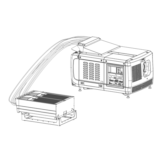
- Page 14 For functionality and reliability, the Prometheus III requires accurate temperature control and cooling. Therefore a liquid cooling system is provided consisting of liquid circuits inside the Prometheus III which are connected via hoses to external coolers. Only cooler models and hoses exclusively developed for this application and approved by Barco are allowed to be used.
-
Page 15: Product Safety Labels
Replacement parts: When replacement parts are required, be sure the service technician has used original Barco replacement parts or authorized replacement parts which have the same characteristics as the Barco original part. Unauthorized substitutions may result in degraded performance and reliability, fire, electric shock or other hazards. -
Page 16: High Brightness Precautions: Hazard Distance (Hd)
3.0 meter to prevent potential exposure, for example by an individual sitting on another individual's shoulders, within the HD. Sufficiently large separation height may be achieved by mounting the image projector on the ceiling or through the use of physical barriers. R5906897 /02 Prometheus III... - Page 17 Image 1-2. The restricted area sticker can be replaced by a sticker with only the symbol. RESTRICTED AREA Image 1-2 USA market For LIPs (Laser Illuminated Projectors) installed in the USA market other restriction zone conditions apply. R5906897 /02 Prometheus III...
-
Page 18: Hd For Fully Enclosed Projection Systems
• This product can only be installed by Barco or sold or leased only to valid laser light show variance holders. In other words our installers are required to have an approved laser light show variance. Such installers may currently hold a valid variance for production of Class IIIb and IV laser light shows and/or for incorporation of the RG3 LIPs into their shows. - Page 19 The light emitted from the screen within the observation shall never exceed the RG2 exposure limit, determined at 10 cm. The HD can be neglected if the measured light at the screen surface is below 5000 diffuse cd/m² or 15000 LUX. R5906897 /02 Prometheus III...
-
Page 20: Hd In Function Of Modifying Optics
Safety 1.7 HD in function of modifying optics Hazard Distance Prometheus III 4,00 3,50 3,00 2,50 2,00 1,50 1,00 0,50 0,00 1 1,1 1,2 1,3 1,4 1,5 1,6 1,7 1,8 1,9 2 2,1 2,2 2,3 2,4 2,5 2,6 2,7 2,8 2,9 3 3,1 3,2 3,3 3,4 3,5 3,6 3,7 3,8 3,9 4... -
Page 21: General
• PROMETHEUS III Barco provides a guarantee relating to perfect manufacturing as part of the legally stipulated terms of guarantee. Observing the specification mentioned in this chapter is critical for projector performance. Neglecting this can result in loss of warranty. -
Page 22: Installation Requirements
General 2.1 Installation requirements Environmental conditions The table below summarizes the physical environment in which the Prometheus III may be safely operated or stored. Operating Non-Operating Environment Ambient Temperature 10°C (50°F) to 35°C (95°F) -15°C (5°F) to 60°C (140°F) Air cleanliness Clean office environment (equivalent with n.a. -
Page 23: About The Delivered Packages
The cooler weights ±32 kg (±70.6 lb). Barco offers a pedestal for the Prometheus III. This universal pedestal allows a solid and easy setup of the projector. The universal pedestal has a separate compartment to install the UPS unit for the Prometheus III. - Page 24 Image 2-7: Cooler protection grid (option for Stand alone cooler) Option The following optional accessories are available: • A metal grid can be use to protect the radiators from damage due to direct blows or falling objects and such. R5906897 /02 Prometheus III...
-
Page 25: Unpacking The Projector
8 mm Allen wrench. • 13 mm open end wrench. • 17 mm open end wrench. How to unpack Loosen the banding by pulling the free end of the banding loop in the clip. Take off the box cover. R5906897 /02 Prometheus III... - Page 26 General Image 2-9: Open banding Open the box. Take out the small box between the outer and inner box containing the manuals. Remove the outer carton box Image 2-10 Remove the inner carton box. R5906897 /02 Prometheus III...
- Page 27 Take off the upper carton plate (1) Remove from the wooden pallet (2) Image 2-12 Take the projector from the wooden board by gripping the bottom of the projector and place the projector on the pedestal. Image 2-13 R5906897 /02 Prometheus III...
-
Page 28: Initial Inspection
This check should confirm that there are no broken knobs or connectors, that the cabinet and panel surfaces are free of dents and scratches, and that the operating panel is not scratched or cracked. The Barco Sales and Service office should be notified as soon as possible if this is not the case. -
Page 29: Installation Process
The installation of the complete system is split up in two parts, installation of the projector and the installation of the cooler unit as top pack or stand alone pack. Overview • Installation process projector • Installation process stand alone cooler • Software upgrade • Starting up and adjusting the system R5906897 /02 Prometheus III... -
Page 30: Installation Process Projector
(Option) Installation of the optional Communicator touch panel on the projector. In both stand alone and top pack solutions, it is possible to install a Barco communicator touch panel. Note: If the customer chose the top pack solution it is recommended to install the top cooler first, then the touch panel. -
Page 31: Starting Up And Adjusting The System
Tilt the projector in case you can not SHIFT the image completely upon the screen. See “Lens shift, zoom & focus”, page 69. See chapter “Local keypad of the Prometheus III ”, page 82, for detailed description of the Local Keypad buttons. - Page 32 Installation process R5906897 /02 Prometheus III...
-
Page 33: Physical Installation Projector
• Positioning the Prometheus III at port window • Access to the power connection • Connecting the Prometheus III with the power net • Power loop through to the projector electronics • Connecting a UPS to the projector electronics R5906897 /02... -
Page 34: Positioning The Prometheus Iii At Port Window
WARNING: The installation of the Prometheus III requires at least 4 persons. General guide lines • Use a solid pedestal to put the Prometheus III on. Ensure that the pedestal can handle the weight of the projector and that all feet of the projector are captured. •... - Page 35 Later, when the projector is up-and-running, adjust precise image geometry and placement. Projector tilting In an ideal installation, the Prometheus III lens surface is centered with and parallel to the screen. This orientation helps to ensure optimized lens performances with minimal offset. If this position is not possible (such as when the projector is significantly higher than the center of the screen), it is better to rely on offset rather than extra tilt.
-
Page 36: Access To The Power Connection
CAUTION: The projector may tilt maximum 15° forward and maximum 15° backwards. This includes the tilt created by the projector feet and the tilt created by the pedestal. Barco offers a pedestal for the Prometheus III projector. This universal pedestal allows you to easily tilt the projector forward up to 6°. -
Page 37: Connecting The Prometheus Iii With The Power Net
Image 4-7: Terminal strip accessible The terminal strip and connection plate is accessible. 4.3 Connecting the Prometheus III with the power WARNING: The total electrical installation should be protected by an appropriate rated and readily accessible disconnect switch, circuit breakers and ground fault current interrupters. The installation shall be done according to the local electrical installation codes. -
Page 38: Power Loop Through To The Projector Electronics
This procedure explains how to provide the projector electronics with power in case no UPS unit is used. Note that the projector is by default configured for use without UPS. So, the short power link cable is already installed. R5906897 /02 Prometheus III... -
Page 39: Connecting A Ups To The Projector Electronics
Release the fixation spring. 4.5 Connecting a UPS to the projector electronics WARNING: Only use UPS units which are suitable for the Prometheus III. See chapter ”General”, “Installation requirements” for more information about the requirements of the UPS. How to connect the UPS Install the UPS according to the instructions of the manufacturer and the local regulations. - Page 40 CAUTION: The electrical connection with the UPS INLET socket of the projector must be done with a certified AC power supply cord (minimum 0,75 mm² or 18 AWG and minimum 300V) CAUTION: Do not use the power OUTLET socket of the projector to provide power to other equipment! R5906897 /02 Prometheus III...
-
Page 41: Physical Installation Stand Alone Cooler
Installing the brackets on the cooler housing • Mounting the cooler housing on the frame • Insert the cooler units • Mount the filters • Cabling and tubing • Mount protection grid for the LCM cooler modules (option) R5906897 /02 Prometheus III... -
Page 42: Supported Mounting Position
Stacking Standalone coolers: It is NOT allowed to stack multiple cooler modules on top of each other. The air intake of the upper cooler would take in the “hot” air of the lower cooler, even at a distance of 1m apart. R5906897 /02 Prometheus III... - Page 43 (more or less 15kg) and if the safety clic fails and the cooler screw is not fixed, the cooler will simply fall to the ground! In this orientation it is also less practical to remove a cooler for service. R5906897 /02 Prometheus III...
-
Page 44: Assembling The Housing
Landscape Mode with cooling tubes to the left (only one authorized position). Landscape Mode with cooling tubes to the right (not authorized). 5.2 Assembling the housing Housing parts The housing parts are delivered as a flat pack and should be mounted together at the customers side. R5906897 /02 Prometheus III... - Page 45 Physical installation stand alone cooler Image 5-7 Image 5-8 This flat pack contains the following parts: Top plate Side covers M4 Hex Screws M3 Hex Screws Support for middle bracket Side fixation Position plate R5906897 /02 Prometheus III...
- Page 46 Insert the side fixation on both side covers. Slide it in for about 4 cm. Make sure you insert the side fixation for the left side cover on the opposite side. Turn in a set screws (M3) on each side but do not fasten it yet. R5906897 /02 Prometheus III...
- Page 47 Note: There may be paint job markings left on the internal side of the side covers (e.g. in the grooves for the positioning pin). These markings are no thread nor should they be mistaken for such. R5906897 /02 Prometheus III...
- Page 48 Turn in a set screw (M3) as indicated in reference 1. Tip: Put in place the screws, without tightening them, before slide the middle bracket. It is more easy to positioning the screws when the middle bracket is not in place. R5906897 /02 Prometheus III...
- Page 49 Tip: Put in place the screws, without tightening them, before slide the top plates. It is more easy to positioning the screws when the top plates are not in place. Image 5-14 Hook the middle bracket support into the middle bracket. Turn in the fixation screw (M4). R5906897 /02 Prometheus III...
-
Page 50: Mounting The Housing On The Frame
5.3 Mounting the housing on the frame Required tools Allen key 3 mm How to mount Place the housing on the cooler frame so that both positioning pins (1) on the housing match the notches in the frame. R5906897 /02 Prometheus III... - Page 51 Fixate the clamp fully so that it fits behind the rib on the housing. Drive in a screw (M3) to connect the clamp to the frame. Repeat for the other side. Place the support for the middle bracket on the frame as indicated. Drive in the fixation screw (M4). R5906897 /02 Prometheus III...
- Page 52 On the front side, drive in the 2 screws (M4), one at the left and one at right. Image 5-18 Note: Only the hole referenced 1 must be used. The other holes around are not used at this step of the procedure. R5906897 /02 Prometheus III...
-
Page 53: Preparing The Stand Alone Frame
It can be mounted in portrait mode (A) or in landscape mode (B). Note: In portrait mode the coolers must be mounted with the cooling tubes up. In landscape mode the cooler must be mounted with the cooling tubes to the left. R5906897 /02 Prometheus III... -
Page 54: Installing The Brackets On The Cooler Housing
2 equal rear brackets • 4 Hex Screws M5x8 • 4 Hex Screws M5x12 How to install the brackets Fixate the U-bracket (on both sides) to the side of the cooler housing with 2 screws (M5x12). R5906897 /02 Prometheus III... -
Page 55: Mounting The Cooler Housing On The Frame
At this step of the procedure, the frame is considered as being in its final position, and already fixed, if the wall mounting option has been chosen. See chapter dedicated to the standalone frame preparation. How to mount Place the housing on the frame. R5906897 /02 Prometheus III... - Page 56 Note: The two U-Brackets are not fixed in same manner. Here, the concerned U-bracket, is situated in the lower right corner of the housing when you look at the device on the side of the cooler inputs. R5906897 /02 Prometheus III...
-
Page 57: Insert The Cooler Units
Check if the two indicated screws (reference 1) are present. If it is the case, remove this screws. The use of these screws may become necessary to fixate the cooler in the cooler assembly when the captive screws (reference 2) does not work. R5906897 /02 Prometheus III... -
Page 58: Mount The Filters
Slide the second cooler unit in the cooler housing. Fixate both units by closing the both captive screws. 5.8 Mount the filters Required tools Flat screw driver (if screws are too difficult to loosen by hand) R5906897 /02 Prometheus III... - Page 59 Look to the airflow sticker for the correct orientation. Airflow is up. Image 5-30 Place the cover plate back on its location and drive in both fixation screws by hand. Note: Please, don't use any tool! Only hand tighten these screws. R5906897 /02 Prometheus III...
-
Page 60: Cabling And Tubing
(option) General An metal grid (with two fixing screws) is provided in the delivery package. This optional grid can be use to protect the radiators from damage due to direct blows or falling objects and such. R5906897 /02 Prometheus III... - Page 61 . Required tools Flat screwdriver How to mount Slide the grid (reference 1 Image 5-32) in the fixation tabs (reference 2 Image 5-32). Fix the grid with the two fixation screws (reference 3 Image 5-32). R5906897 /02 Prometheus III...
- Page 62 Physical installation stand alone cooler R5906897 /02 Prometheus III...
-
Page 63: Lenses & Lens Holder
About this chapter This chapter gives an overview of available lenses for the Prometheus III and explains how you can select the best suited lens for your specific situation using the lens calculator. Also, it is explained how to install and remove a lens from the projector lens holder and how you can shift, zoom and focus the lens. -
Page 64: Available Lenses
Lenses & lens holder 6.1 Available lenses Which lenses are available for my projector? The table below is subject to changes and was last updated on 22/12/2017. Consult Barco's web site for the most recent information about available lenses. Throw Range... -
Page 65: Lens Installation
For critical situations (fixed installs that use the lens at one of its extreme zoom positions) this should be taken into account. 6.3 Lens installation How to install a lens? Remove the plastic lens holder cover. Put the lock (1) into the unlock position. Take out the plastic cover. R5906897 /02 Prometheus III... - Page 66 Ensure that the lens holder stands in the On-Axis position (horizontal and vertical mid position). Note: The lens holder is placed default in the On-Axis position at factory. Gently insert the lens in such a way that the lens connector matches the socket. R5906897 /02 Prometheus III...
- Page 67 Image 6-5: Fix lens Activate the corresponding lens parameters for the installed lens. (See user guide of the “Communicator” chapter Installation > Advanced > Lens parameters) Caution: Not using the correct lens parameters could result in lens damage. R5906897 /02 Prometheus III...
-
Page 68: Lens Removal
Support the lens with one hand while you unlock the lens holder by sliding the lock handle towards the “unlocked” position as illustrated. Image 6-7: Unlock lens Gently pull the lens out of the lens holder. R5906897 /02 Prometheus III... -
Page 69: Lens Shift, Zoom & Focus
6.5 Lens shift, zoom & focus Motorized lens adjustment The Prometheus III is equipped with a motorized lens shift functionality and a motorized zoom & focus functionality. Maximum shift range The lens can be shifted with respect to the internal optics of the projector (DMD) which results in a shifted image on the screen (Off-Axis). - Page 70 DMD. Field of view. How to shift the lens of the Prometheus III? Use the up and down arrow keys on the local keypad to shift the lens vertically and use the left and right arrow keys on the local keypad to shift the lens horizontally.
-
Page 71: Back Focal Length Adjustment
FLAT and/or for SCOPE. In other words, when it is impossible to focus the image on the screen for FLAT and/or for SCOPE. Note that the lenses for the Prometheus III are varifocal. So, switching between FLAT and SCOPE (zoom action) requires a readjustment of the focus. - Page 72 Turn the three Scheimpflug adjustment nuts, reference 1, 2 and 3 Image 6-17, until the front of the nut (reference 5 Image 6-17) is equally aligned with the front of the threaded rod (reference 6 Image 6-17). Use a 13mm nut driver. R5906897 /02 Prometheus III...
- Page 73 Scheimpflug adjustment nuts, reference 1, 2 and 3 Image 6-19, equally in or out until the center of the projected image is sharp. Attention: Keep in mind the turning direction of the Scheimpflug adjustment nuts for further adjustment instructions in this procedure. R5906897 /02 Prometheus III...
- Page 74 Lens Holder front plate. CAUTION: Skip the action, in the Scheimpflug adjustment procedure, to turn the three Scheimpflug adjustment nuts until the front of the nut is equally aligned with the front of the threaded rod! R5906897 /02 Prometheus III...
-
Page 75: Scheimpflug Adjustment
Image 6-23: Scheimpflug adjustments Indication on drawing Function 1, 2 and 3 Scheimpflug adjustment nuts Locking nut A, B, C and D Set screws a, b, c and d lock nuts 1, 2 and 3 are adjustment points. R5906897 /02 Prometheus III... - Page 76 Turn the Scheimpflug adjustment nuts 1, 2 and 3 until the front of the nut is equally aligned with the front of the threaded rod. Adjust the focus in the center of the screen (F) using the motorized focus control. Image 6-25: Center focusing Sharpen bottom left corner of the screen by adjusting nut 1. R5906897 /02 Prometheus III...
- Page 77 Lenses & lens holder Image 6-26: Left bottom focusing Sharpen bottom right corner of the screen by adjusting nut 2. Image 6-27: Right bottom focusing Sharpen top right corner of the screen by adjusting nut 3 R5906897 /02 Prometheus III...
-
Page 78: Fixation Of The Lens Holder Front Plate
Start the fixation as follows (steps must be followed strictly) : Project the framing test pattern for FLAT & SCOPE. Zoom the projected image until the edges of the projected test pattern matches with the edges of the projection screen. FLAT SCOPE Image 6-29 R5906897 /02 Prometheus III... - Page 79 Tip: Fasten the set screw and the Scheimpflug nut alternately, without disturbing the projected image, until the Scheimpflug nut and set screw are completely tightened. Image 6-31 Fasten the lock nut at the lower left of the Lens Holder. Use a 10mm nut driver. R5906897 /02 Prometheus III...
- Page 80 Lenses & lens holder R5906897 /02 Prometheus III...
-
Page 81: Input & Communication
Input & communication Overview • Introduction • Local keypad of the Prometheus III • Integrated Cinema Processor (ICP) • HD-SDI Input Module (optional) • Quad 3G-SDI Input Module (optional) • Integrated Media Block/Server (optional) • Cinema Controller of the Prometheus III... -
Page 82: Introduction
General The Input & Communication side of the Prometheus III consists of a Local Keypad and a card cage with four slots. The rear side of the projector is equipped with a tail light which reflects the status of the projector. -
Page 83: Integrated Cinema Processor (Icp)
The zoom keys (8) allow you to zoom in or out the projected image on the screen. 7.3 Integrated Cinema Processor (ICP) In case the projector is equipped with a Barco ICMP no ICP board is inserted. All ICP functionality is integrated in the Barco ICMP. - Page 84 • Handles unpacking of special video formats The ICP board spare part kit is not default programmed for a Prometheus III projector. When using this board in a Prometheus III projector the software must be re-installed after installation of the board.
-
Page 85: Hd-Sdi Input Module (Optional)
Input & communication 7.4 HD-SDI Input Module (optional) Not available for purchase at Barco for use in Taiwanese market. Depending on the projector configuration the projector card cage is either equipped with an ICP or ICMP. In case an ICP is installed then an IMB, IMS, or HDSDI input module can be optionally inserted into the slot below the ICP. - Page 86 Progressive SF - YCbCr 3G - Level B - Dual Single 2nd field dominant stream Dual (separate left / right eye) HDSDI 3D 4:2:2 10 Progressive YCbCr HDSDI - Single bits/color Interleaved Dual (separate left / right eye) R5906897 /02 Prometheus III...
- Page 87 4:2:2 10 Progressive YCbCr 3G - Level B - Dual Single bits/color stream 3G - Level B - Single link HDSDI HFR 4:2:2 10 Progressive YCbCr HDSDI - Single bits/color Interleaved Progressive SF- 1st field dominant R5906897 /02 Prometheus III...
-
Page 88: Quad 3G-Sdi Input Module (Optional)
/ right eye) 7.5 Quad 3G-SDI Input Module (optional) Location and source input ports QUAD 3G/SDI INPUT SYNC OK SYNC OK SYNC OK SYNC OK Image 7-5 The following input combinations are possible : A, B, A+B, A+B+C+D R5906897 /02 Prometheus III... - Page 89 3G-level B-Dual link 4:4:4 10 Progressive 3G-level A-Single bits/color link 3G-level B-Dual link 4:4:4 12 Progressive XYZ/ 3G-level A-Single bits/color link 3G-level B-Dual link HD-SDI 4:4:4 10 Progressive HD-SDI-Dual link Single Duallink AB bits/color R5906897 /02 Prometheus III...
- Page 90 4:2:2 10 Progressive YCbCr 3G - Level B - Single bits/color Dual stream Dual (separate left / right eye) Only for Quad input board (this is a split screen setting, when selected, it turns on split-screen) R5906897 /02 Prometheus III...
- Page 91 3G - Level A - Single bits/color Interleaved Dual (separate left / right eye) 3G - Level B - Single Interleaved Dual (separate left / right eye) 4:4:4 12 Progressive XYR/ 3G - Level A - Single bits/color Interleaved R5906897 /02 Prometheus III...
- Page 92 YCbCr 3G - Level A - Single 1st field dominant Interleaved Dual (separate left / right eye) Progressive SF- YCbCr 3G - Level A - Single 2nd field Interleaved Dual dominant (separate left / right eye) R5906897 /02 Prometheus III...
- Page 93 3G - Level A - Single 1st field dominant Quad Link 3G - Level B - Quad Link Progressive SF - XYZ/ 3G - Level A - Single 2nd field Quad Link dominant 3G - Level B - Quad Link R5906897 /02 Prometheus III...
-
Page 94: Integrated Media Block/Server (Optional)
7.6 Integrated Media Block/Server (optional) Not available for purchase at Barco for use in Taiwanese market. Depending on the projector configuration the projector card cage is either equipped with an ICP or ICMP. In case an ICP is installed then an IMB, IMS, or HDSDI input module can be optionally inserted into the slot below the ICP. -
Page 95: Cinema Controller Of The Prometheus Iii
DHCP server. The Prometheus III can be connected to a WAN (Wide area network) (reference 2 Image 7-9). Once connected to the WAN, users can access the projector from any location, inside or outside (if allowed) their company network using the Communicator software. - Page 96 Color Color Input Scan type Sampling Source standard Vertical rate space depth Single DVI VESA (640x480) Progressive 4:4:4 8 bit Single DVI VESA (640x480) Progressive 4:4:4 8 bit Single DVI VESA (800x600) Progressive 4:4:4 8 bit R5906897 /02 Prometheus III...
- Page 97 Two columns of 2048x2160 are needed, where DVI-A is left image and DVI-B is right image. Use Rec 709 for 4K as PFC file. 2048 2048 DVI-A DVI-B 8 bit 8 bit 24 Hz 24 Hz Image 7-11: DVI-4K R5906897 /02 Prometheus III...
- Page 98 Input & communication R5906897 /02 Prometheus III...
-
Page 99: Icmp
ICMP HDMI 1.4 specifications • ICMP status LEDs • ICMP HDD status LEDs • ICMP device certificate • ICMP configuration via Communicator • ICMP reset • Obtaining the Barco ICMP certificate • Removing a HDD from the ICMP R5906897 /02 Prometheus III... - Page 100 ICMP • Installing a HDD into the ICMP R5906897 /02 Prometheus III...
-
Page 101: Icmp Introduction
As an integrated component of the projector, installation and maintenance of the ICMP requires the same skills and the same precautions as an intervention on the projector itself. For order info see www.barco.com. Front face of the ICMP The last produced model is equipped with two HDMI 2.0 as video source. -
Page 102: Icmp Hdd
The ICMP (reference 1) is inserted into the former ICP slot and IMB slot next to the Barco Cinema Controller (reference 2). ICMP location in the Card Cage of a DPxk B-series, C-series, BLP-series or CLP series projector. - Page 103 HDD models validated by Barco Only the original HDD spare parts provided by Barco or models validated by Barco (see list below) can be used in the ICMP. All deviations from this rule void warranty.
-
Page 104: Icmp Communication Ports
The ICMP can be connected to a USB 2.0 Media to load content. The USB port can be used to load content (DCP) or keys (KDM). NOTE: It is recommended to use the USB 3.0 ports for faster ingest. R5906897 /02 Prometheus III... -
Page 105: Icmp Source Input Ports
The last produced model is equipped with two HDMI 2.0 (Reference 8, Image 8-8) as video source. Image 8-8: ICMP (with HDMI 2.0). Some models with DisplayPorts (Reference 11, Image 8-9) and HDMI 1.4 (Reference 10, Image 8-9) are still present on the field. Image 8-9: ICMP (with DisplayPort and HDMI 1.4). R5906897 /02 Prometheus III... -
Page 106: Icmp Displayport Specifications
8 bpc, 10 bpc Single 1920 x 1080 @ 60 fps 8 bpc, 10 bpc Single 1920 x 1200 @ 60 fps 8 bpc, 10 bpc Single 2048 x 1080 @ 48, 60 fps 8 bpc, 10 bpc Single R5906897 /02 Prometheus III... - Page 107 Active Pixels, and Active Lines Vertical Refresh 8 bits/color - 10 bits/color Frame locked • All input resolutions are scaled towards the desired resolution specified in the screen presentation file. • Fractional frame rates = (Hz*1000)/1001 R5906897 /02 Prometheus III...
-
Page 108: Icmp Sdi Specifications
1080p 50/60 (Level A) 3Gb/s 1080p 4:4:4 (Level B) 3G HD-SDI uses a higher data rate (2.97 Gb/s). This allows a single cable interface to achieve the same capabilities of a Dual-Link HD-SDI implementation. Not supported in Alchemy R5906897 /02 Prometheus III... - Page 109 23.976 23.976 Segmented frame SMPTE 428-9 2048 x 1080 Y Cb Cr 4:2:2 10-Bit (SMPTE RP211) 29.97 29.97 SMPTE 274M 1920 x 1080 Interlaced 29.970 59.940 Y Cb Cr 4:2:2 10-Bit Dual-Link HD-SDI (SMPTE 372M) formats R5906897 /02 Prometheus III...
- Page 110 The Dual-Link HD-SDI interface can be used to carry a single 4:4:4 image, having a color depth of 10 or 12 bit per component. Both RGB (XYZ) and Y Cb Cr color spaces are supported. SMPTE 424M 3G HD-SDI 2.970 Gb/s SIGNALS 3G HD-SDI (SMPTE 425) formats mainly used to carry stereoscopic images. R5906897 /02 Prometheus III...
-
Page 111: Icmp Hdmi 2.0 Specifications
Both HDMI 2.0 inputs are fully compliant with the HDMI 1.4, 1.4a, 1.4b, 2.0 and 2.0a revisions of the HDMI specification. only supported in 3G level A mapping, others formats are supported in both level A and level B mapping. R5906897 /02 Prometheus III... - Page 112 The ICMP is not supporting Ethernet-over-HDMI and such specific cables are thus not required. HDMI 2.0 Supported 2D Formats Color coding Bit depth Format Frame Rate 1280x720 23.976 YCbCr 4:4:4 YCbCr 4:2:2 29.97 59.94 1280x720 119.88 YCbCr 4:4:4 YCbCr 4:2:2 1920x1080 23.976 2048x1080 YCbCr 4:4:4 YCbCr 4:2:2 29.97 59.94 R5906897 /02 Prometheus III...
- Page 113 YCbCr 4:4:4 YCbCr 4:2:2 3840x2160 23.976 4096x2160 24 25 YCbCr 4:4:4 29.97, 30 YCbCr 4:2:2 3840x2160 4096x2160 59.94 YCbCr 4:4:4 YCbCr 4:2:2 HDMI 2.0 Supported Audio Formats Sample coding Sample Rate Bit depth Format L-PCM 44.1 88.2 R5906897 /02 Prometheus III...
-
Page 114: Icmp Hdmi 1.4 Specifications
HDMI- compliant device ("the source device") to a compatible computer monitor, video projector, digital television, or digital audio device. HDMI is a digital replacement for existing analog video standards. R5906897 /02 Prometheus III... - Page 115 YCbCr 4:2:2 1280x720 23.976 YCbCr 4:4:4 YCbCr 4:2:2 29.97 59.94 119.88 1680x720 23.976 YCbCr 4:4:4 YCbCr 4:2:2 29.97 59.94 119.88 1920x1080 23.976 2048x1080 YCbCr 4:4:4 YCbCr 4:2:2 29.97 59.94 1920x1080 2048x1080 119.88 YCbCr 4:4:4 YCbCr 4:2:2 R5906897 /02 Prometheus III...
- Page 116 HDMI 1.4 Supported 3D (Frame Packing) Formats Color coding Bit depth Format Frame Rate 1280x720 59.94 1920x1080 23.98 HDMI 1.4 Supported 3D (Top Bottom) Formats Color coding Bit depth Format Frame Rate 1280x720 59.94 1920x1080 23.98 R5906897 /02 Prometheus III...
-
Page 117: Icmp Status Leds
Security Manager - FPGA self-test Green Blinking Green Starting Applications Green Green Applications started in normal mode Green Orange Applications started in degraded mode Blinking Red FIPS error Green Blinking Orange Update ongoing Orange Orange Update done R5906897 /02 Prometheus III... -
Page 118: Icmp Hdd Status Leds
“Installing a HDD into the ICMP”, page 125. Ensure to insert the HDD firmly. Switch on the power. Result: As soon the new HDD is detected by the ICMP the rebuild of the RAID is started (Blinking red LED). R5906897 /02 Prometheus III... -
Page 119: Icmp Device Certificate
Purpose of the Barco ICMP device certificate The device certificate (*.pem) of the Barco ICMP is a digital certificate signed by Barco which is required when ordering the KDM to play a DCP that is ingested on the ICMP. The device certificate is stored inside the ICMP and on a web server. - Page 120 Internet. The certificates are also used to sign messages, which ensures that messages have not been tampered with. *.pem Privacy-enhanced Electronic Mail. File format used to distribute digital signed certificates. Base64 encoded DER certificate, enclosed between "———BEGIN CERTIFICATE———" and "———END CERTIFICATE———" R5906897 /02 Prometheus III...
-
Page 121: Icmp Configuration Via Communicator
• Verify internal clock of the ICMP. All installation and maintenance operations on the ICMP are performed via Communicator, the Barco configuration software. Please refer to the Communicator user guide for further information. R5906897 /02 Prometheus III... -
Page 122: Icmp Reset
ICMP hardware reset button a few seconds (reference 3 Image 8-13) . Warning: Resetting the ICMP with the hardware reset button may cause damage to the content on the HDDs. A re-configuration of the whole system may be required! R5906897 /02 Prometheus III... -
Page 123: Obtaining The Barco Icmp Certificate
WARNING: Resetting the ICMP with the hardware reset button may cause damage to the content on the HDDs. A re-configuration of the whole system may be required! 8.14 Obtaining the Barco ICMP certificate Required tools Smartphone (with auto-focus) or control software (e.g. Communicator, Commander or WEB Commander) Using the CertID label to download the ICMP certificate Scan the QR code (reference 1) on the front face of the ICMP with a smartphone. -
Page 124: Removing A Hdd From The Icmp
Moving the latch towards the left. Image 8-15 Push the unlock button to open the handle. Image 8-16 Pull the HDD out of its slot. Image 8-17 To install the HDD see procedure “Installing a HDD into the ICMP”, page 125. R5906897 /02 Prometheus III... -
Page 125: Installing A Hdd Into The Icmp
This procedure assumes that the HDD slot of the ICMP is empty. If not, see procedure “Removing a HDD from the ICMP”, page 124. CAUTION: Always use a new empty spare part HDD approved by Barco to replace a malfunction HDD. Do not use a HDD from another ICMP HDD set. - Page 126 200 GB per hour. Once the RAID is completed the red LED turns off. CAUTION: It's strongly recommended to complete the RAID recovery process prior to starting a show. This to ensure that the content integrity is preserved and that the show is not interrupted. R5906897 /02 Prometheus III...
-
Page 127: Communicator Touch Panel
Communicator Touch Panel Overview • Introduction • Installation of the touch panel interface R5906897 /02 Prometheus III... -
Page 128: Introduction
Flexible touch panel interface The touch panel interface can be mounted upon a swivel arm which easily fits on top of the Prometheus III. One central locking mechanism of the swivel arm allows an instant fixation of the touch panel interface in any position. -
Page 129: Installation Of The Touch Panel Interface
Image 9-3: Assemble swivel arm Slide a washer (M) over the base of the swivel arm and Insert the base of the swivel arm into the mounting hole at the top of the Prometheus III as illustrated. R5906897 /02 Prometheus III... - Page 130 Image 9-5: Mount touch panel Connect the circular plug of the multi cable with the circular socket at the rear side of the Prometheus III. Image 9-6 Attach the multi cable to the swivel arm using the two Velcro strips.
- Page 131 Communicator Touch Panel Connect the DC plug, the RJ45 Ethernet plug and the D-SUB plug into their respective sockets on the touch panel interface. Image 9-7: Connections R5906897 /02 Prometheus III...
- Page 132 Communicator Touch Panel R5906897 /02 Prometheus III...
-
Page 133: Starting Up
Starting up About this chapter This chapter contains the switch ON and switch OFF procedures of the Prometheus III. These procedures enumerate all the important points which have to be checked prior to switching ON the projector. This is to ensure a safe start up of the projector. -
Page 134: Switching On The Prometheus Iii
Make sure that the lens cap is removed and the correct lens is installed for your application. See chapter “Lens selection”, page 64. Make sure the projector is correctly connected to the power net. See chapter “Connecting the Prometheus III with the power net”, page 37. -
Page 135: Removal And Installation Of The Projector Covers
Removal of the side cover • Installation of the front cover • Installation of the input cover • Installation of the light source cover • Installation of the rear cover • Installation of the side cover R5906897 /02 Prometheus III... - Page 136 Removal and installation of the projector covers Location of the covers Image 11-1 Light source cover Input cover Front cover Side cover Rear cover All cover can be individually removed. R5906897 /02 Prometheus III...
-
Page 137: Removal Of The Light Source Cover
Image 11-2: Light Source cover, loosening screws Push both lock to each other to release the locks and pull at the same time the bottom side of the cover away form the projector. Image 11-3: Light Source cover, locks Remove the cover. R5906897 /02 Prometheus III... -
Page 138: Removal Of The Rear Cover
Remove the rear cover of the projector doing the following: gently pull out the top covers of the rear cover (2). then move the rear cover away from the projector. 11.3 Removal of the input cover Required tools Flat screwdriver R5906897 /02 Prometheus III... -
Page 139: Removal Of The
Pull the bottom side of the cover to you until the cover is unlocked. Slide the full cover away from the projector. Image 11-7: Input cover removal 11.4 Removal of the front cover Required tools Flat screwdriver How to remove Check if the lens is removed. R5906897 /02 Prometheus III... - Page 140 Remove the front cover as follow: standing in front of the projector, pull the top side of the cover to you until it is unlocked. slide the cover away from the projector. Image 11-9: Remove front cover R5906897 /02 Prometheus III...
-
Page 141: Removal Of The Side Cover
Image 11-10: Captive screws Push both lock to each other to release the locks and pull at the same time the bottom side of the cover away form the projector. Image 11-11: Unlock side cover Take off the cover. R5906897 /02 Prometheus III... -
Page 142: Installation Of The
Gently push the top side of the cover into position. Ensure that the locking studs click into their receivers. Image 11-13: Mount front cover Secure the front cover by locking the captive screw in the middle at the bottom of the front cover. R5906897 /02 Prometheus III... -
Page 143: Installation Of The Input Cover
Image 11-14: Secure front cover Reinstall the rubber dust ring around the lens holder. 11.7 Installation of the input cover Required tools Flat screwdriver How to install Place the top side of the cover on its place. R5906897 /02 Prometheus III... -
Page 144: Installation Of The Light Source Cover
Image 11-16: Secure input cover Secure the cover by fastening the captive screw. 11.8 Installation of the light source cover Required tools Flat screwdriver How to install Place the top side of the cover on its place. R5906897 /02 Prometheus III... -
Page 145: Installation Of The Rear Cover
Bring the rear cover towards its final position. Gently push the locking studs into the receivers (1). Note: Gently install the back cover, ensure the UPS cable is not damaged by guiding it into the foreseen cavity in the cover. R5906897 /02 Prometheus III... -
Page 146: Installation Of The Side Cover
Gently move the bottom side of the cover towards the projector Push both lock to each other and push at the same time the cover against the projector frame. Release both locks so that they lock in their receivers. R5906897 /02 Prometheus III... - Page 147 Removal and installation of the projector covers Image 11-21: Lock side cover Secure the cover by fasting both captive screws. Image 11-22: Lock side cover R5906897 /02 Prometheus III...
- Page 148 Removal and installation of the projector covers R5906897 /02 Prometheus III...
-
Page 149: Preventative Maintenance Actions
Contact your service partner for more information about maintenance services. Overview • Monthly maintenance actions • Three monthly maintenance actions R5906897 /02 Prometheus III... -
Page 150: Monthly Maintenance Actions
12.2 Three monthly maintenance actions MAINTENANCE TYPE B (perform every three months) The 3 month maintenance actions, listed below, may be performed by a trained projectionist who is familiar with potential hazards associated with the product. R5906897 /02 Prometheus III... - Page 151 Verify the internal clock of the ICMP with real time clock. ICMP version 1.2.1 is required at least. Correct if needed. Communicator version 5.0 or higher is required. See user guide of Communicator for detailed instructions. R5906897 /02 Prometheus III...
- Page 152 Preventative maintenance actions R5906897 /02 Prometheus III...
-
Page 153: Maintenance
• Washing and drying the dust filters • Cleaning the lens • Cleaning the exterior of the projector • Check cooling liquid level • Cooling liquid refill • Authorization to clear security warning on the projector R5906897 /02 Prometheus III... -
Page 154: Remove And Clean The Front Dust Filter
These dust filters are fragile. Clean them gently! Mount the dust filter Insert the dust filter with the “up” indication to the top of the projector. R5906897 /02 Prometheus III... -
Page 155: Remove And Clean Both Bottom Dust Filters
13.2 Remove and clean both bottom dust filters How to remove Remove the side cover. Slide out the bottom front dust filter. Image 13-3: Bottom front dust filter Slide out the bottom back dust filter. Image 13-4: Bottom back dust filter R5906897 /02 Prometheus III... -
Page 156: Check The Cooler Dust Filters
In case the filter is contaminated with grease wash and dry the dust filter. See cleaning procedure “Washing and drying the dust filters”, page 157. In case the filter contains dust but doesn't feel greasy then clean these filters with compressed air. These filters are not fragile and this method is more easier. R5906897 /02 Prometheus III... -
Page 157: Vacuum Cleaning Of The Dust Filters
13.5 Washing and drying the dust filters About filter washing and drying For environments where popcorn grease and such can contaminate the filters, Barco advises the client to purchase one extra set of filters to cover drying time, as well as taking following extra precautions and instructions pertaining to filter cleaning and drying. -
Page 158: Cleaning The Lens
See https://my.barco.com for the correct replacement part. 13.6 Cleaning the lens To minimize the possibility of damage to optical coatings, or scratches to lens surfaces follow the cleaning procedure as described here precisely. R5906897 /02 Prometheus III... -
Page 159: Cleaning The Exterior Of The Projector
Remove the left side cover (Light Processor side). “Removal of the side cover”, page 141. Check the liquid cooling level in the reservoir. Pressurized air cans are not efficient if there is too much dust on the surface, the pressure is too low R5906897 /02 Prometheus III... -
Page 160: Cooling Liquid Refill
Order info cooling liquid B1909086K : bottle of 1 liter cooling liquid. Required parts Cooling liquid How to refill Remove the side cover, “Removal of the side cover”, page 141. Open the filler cap by turning it anti clockwise. R5906897 /02 Prometheus III... -
Page 161: Authorization To Clear Security Warning On The Projector
Security key (Dallas iButton®). • Authorization pin code. Authorization procedure to clear security warning Ensure that all modules are properly installed. Start up the projector (standby mode). Initiate authorization by holding the security key in the security socket D.. R5906897 /02 Prometheus III... - Page 162 In case of a correct code entry, the color of the backlight of the numeric keys 1 to 10 changes to green for 1 second and then back to blue. Each attempt to clear the security warning and its result (successfully or unsuccessfully) is logged inside the projector. R5906897 /02 Prometheus III...
-
Page 163: Convergence
This chapter describes how to prepare the projector for convergence adjustment and how to adjust the convergence. Overview • Open the sealed compartment • Close the sealed compartment • Convergence controls • Red on blue convergence • Green on blue convergence R5906897 /02 Prometheus III... -
Page 164: Open The Sealed Compartment
How to open the sealed compartment Remove both hexagon head cap screws (1). Image 14-1: Sealed cover fixation Lift up the cover plate slightly using both lower lips (2) and then remove the cover by taking it away from the projector. R5906897 /02 Prometheus III... -
Page 165: Close The Sealed Compartment
How to close the sealed compartment Hook the cover plate on the studs. Image 14-3: Sealed cover, mount Slide the cover downwards by pushing on both lips until it is in its correct position. Drive in both fixation screws (1). R5906897 /02 Prometheus III... -
Page 166: Convergence Controls
Red channel, knob number 1 (position of knob Green channel, knob number 4 can slightly differ) Green channel, knob number 5 Red channel, knob number 2 Green channel, knob number 6 Red channel, knob number 3 R5906897 /02 Prometheus III... -
Page 167: Red On Blue Convergence
DO NOT try to force the adjustment beyond this point. The system has an end of travel in both directions, but with excessive force one could cause damage. 14.4 Red on blue convergence Required tools No tools required. R5906897 /02 Prometheus III... -
Page 168: Green On Blue Convergence
To translate GREEN vertically in the Y + direction, turn both [4] and [5] clockwise. Turn screws in equal increments. To translate GREEN vertically in the Y - direction, turn both [4] and [5] anti-clockwise. Turn screws in equal increments. R5906897 /02 Prometheus III... - Page 169 [4] may also be turned in the opposite direction. Slight corrections to Y may be required after rotation. To translate GREEN horizontally in the X + direction, turn [6] clockwise. To translate GREEN horizontally in the X - direction, turn [6] anti-clockwise. Image 14-8: Green on blue convergence R5906897 /02 Prometheus III...
- Page 170 Convergence R5906897 /02 Prometheus III...
-
Page 171: Color Calibration
Color calibration About this chapter This chapter describes the luminance and color calibration process for the Prometheus III. Where applicable references are made to the user guide of the Communicator for detailed menu navigation instructions. The first chapter describes the complete calibration process in chronological order. -
Page 172: Calibration Process
Configure the desired aspect ratio: e.g. FLAT or SCOPE (use most common aspect ratio). Do this by activating the correct LENS file. Position the spectrometer perpendicular to the screen and measure in the center of the screen. Start up Communicator and follow the laser white point calibration wizard. R5906897 /02 Prometheus III... -
Page 173: Color Gamut Calibration
This reference measurement (MCGD), together with the delivered gamut file (TCGD) of the film will introduce a color correction so that the film will be projected with the desired color target. R5906897 /02 Prometheus III... - Page 174 Once all xy coordinates are measured and entered proceed by saving all measured values into a MCGD file. Tip: Put in the MCGD file name the type of projection mode (2D or External 3D) and the aspect ratio (FLAT, SCOPE). R5906897 /02 Prometheus III...
- Page 175 Select target colors. For detailed instructions see user guide of the Communicator. In addition you can check if the corrected colors comply. Use therefore the Communicator. Go to Installation > Color calibration > Verify corrected colors. For detailed instructions see user guide of the Communicator. R5906897 /02 Prometheus III...
- Page 176 Color calibration R5906897 /02 Prometheus III...
-
Page 177: Specifications
Specifications Overview • Specifications of the Prometheus III • Specifications of the ICMP • Dimensions of the Prometheus III • Dimensions of the universal pedestal • Projector air inlets and outlets • Technical Regulations R5906897 /02 Prometheus III... -
Page 178: Specifications Of The Prometheus Iii
Specifications A.1 Specifications of the Prometheus III Overview Projector type Three chip DLP Technology 3 x 1.38" DMD™ Resolution 4,096 x 2,160 (4K) Aspect ratio 1.89:1 Light source Smart Laser Light source lifetime 30,000 Hours (average usage conditions) Light output... - Page 179 37.8 x 53.9 x 40.9 in. (excludes lens - packaged separately) Shipping weight 203 kg / 448 lbs (excludes lens - packaged separately) Storage temperature Storage humidity Standard accessories Certifications Warranty Limited 2 years parts and labor Extendable up to 5 years R5906897 /02 Prometheus III...
-
Page 180: Specifications Of The Icmp
Closed captioning devices: Support for SMPTE 430-10 * 4K 24fps is standard. For 4K 60 fps / 4K 3D on ICMP upgrade modules a license is required. Newly-built 4K Barco Alchemy projectors have the license standard included. Barco Web Commander... - Page 181 ICMP License for HDMI2.0 HDR Licence for Dual Projector TMS support Barco Alchemy is supported by the following Theater Management System (TMS) brands: AAM Screenwriter, Ymagis Melody, CFG-Barco, Unique RosettaBridge, ADDE, CinéDigital Manager, GDC, Proyecson, Real Image, Sony, Hollywoodsoftware/Comscore TCC, Kinoton...
-
Page 182: Dimensions Of The Prometheus Iii
Specifications A.3 Dimensions of the Prometheus III Dimensions 37.5 41.5 381.5 min. 31 Image A-1: Dimensions given in millimeters. R5906897 /02 Prometheus III... -
Page 183: Dimensions Of The Universal Pedestal
Specifications A.4 Dimensions of the universal pedestal Dimensions Image A-2: Dimensions given in millimeters. R5906897 /02 Prometheus III... -
Page 184: Projector Air Inlets And Outlets
Air inlets and outlets Image A-3 A.6 Technical Regulations Certificates Image A-9: Image A-4: Image A-5: Image A-6: CE Image A-7: ETL Image A-8: CEBEC EAC mark Rohs mark mark CCC mark mark Image A-10: RCM mark R5906897 /02 Prometheus III... -
Page 185: B Pin Configurations
Pin configurations Overview • About General Purpose Inputs & Outputs (GPIO) • Pin configurations of the communication ports • Pin configurations of the ICMP communication ports • Pin configurations of the inputs R5906897 /02 Prometheus III... -
Page 186: About General Purpose Inputs & Outputs (Gpio)
GPIO ports. General Purpose inputs The Barco Cinema Controller and the Barco ICMP have each eight (8) opto-isolated general purpose inputs available. These inputs are used to trigger the execution of macro files. For more explanation about the association of a macro to a GPI, consult the user guide of the Communicator. -
Page 187: Pin Configurations Of The Communication Ports
GPO signals may generate unexpected "Rising Edge" events. B.2 Pin configurations of the communication ports RS232IN RS232 IN 2 RXE- Receive Data (RD or RX or RXD) 3 TXE- Transmitted Data (TD or TX or TXD) 5 GND Signal Ground (GND) R5906897 /02 Prometheus III... - Page 188 1000 Base-T — RJ45 port Description Description Pair Color white/green TXD+ TX0+ green TXD- TX0- white/orange RXD+ RX0+ blue — TX1+ white/blue — TX1- orange RXD- RX0- white/brown — Rx1+ brown — RX1- Peripheral Port Name R5906897 /02 Prometheus III...
-
Page 189: Pin Configurations Of The Icmp Communication Ports
RJ-45 pin configuration Image B-3 Audio Channels: AUDIO-AES 1-8 AES pair RJ-45 pin Audio channel 1, 2 3, 4 5, 6 7, 8 AUDIO-AES 9-16 AES pair RJ-45 pin Audio channel 9, 10 11, 12 13, 14 R5906897 /02 Prometheus III... - Page 190 Definition EXT_GPOUT_1_P EXT_GPOUT_1_N EXT_GPOUT_2_P EXT_GPOUT_2_N EXT_GPOUT_3_P EXT_GPOUT_3_N EXT_GPOUT_4_P EXT_GPOUT_4_N GPO 5-8 RJ-45 pin Definition EXT_GPOUT_5_P EXT_GPOUT_5_N EXT_GPOUT_6_P EXT_GPOUT_6_N EXT_GPOUT_7_P EXT_GPOUT_7_N EXT_GPOUT_8_P EXT_GPOUT_8_N General Purpose Input: GPI 1-4 RJ-45 pin Definition EXT_GPIN_1_P EXT_GPIN_1_N EXT_GPIN_2_P EXT_GPIN_2_N EXT_GPIN_3_P EXT_GPIN_3_N R5906897 /02 Prometheus III...
- Page 191 568A + 568A wiring is a straight cable. 568B + 568B wiring is a straight cable. The mapping of the channels is done according to the Ethernet wiring scheme and gives us 100 Ohm per pair. R5906897 /02 Prometheus III...
-
Page 192: Pin Configurations Of The Inputs
B.4 Pin configurations of the inputs DVI-D DVI IN A & B RX2- DDC Data RX0 Shield RX2+ RX2 Shield RX1- RX1+ Hot Plug Detect TMDS Clock Shield RX1 Shield RX0- TMDS RXC+ DDC Clock RX0+ TMDS RXC- R5906897 /02 Prometheus III... -
Page 193: Environmental Information
Environmental Information Overview • Disposal information • China RoHS compliance • Taiwan RoHS compliance • Turkey RoHS compliance • Hazards • Contact information • Production address • Download Product Manual R5906897 /02 Prometheus III... -
Page 194: Disposal Information
Electronic Products” (Also called RoHS of Chinese Mainland), the table below lists the names and contents of toxic and/or hazardous substances that Barco’s product may contain. The RoHS of Chinese Mainland is included in the MCV standard of the Ministry of Information Industry of China, in the section “Limit Requirements of toxic substances in Electronic Information Products”. - Page 195 “Marking for the restriction of the use of hazardous substances in electrical and electronic product” of Chinese Mainland, marked with the Environmental Friendly Use Period (EFUP) logo. The number inside the EFUP logo that Barco uses (please refer to the photo) is based on the “General guidelines of environment-friendly use period of electronic information products”...
-
Page 196: Taiwan Rohs Compliance
備考2.〝〇〞係指該項限用物質之百分比含量未超出百分比含量基準值。 Note 2:“〇” indicates that the percentage content of the restricted substance does not exceed the percentage of reference value of presence. 備考3.〝—〞係指該項限用物質為排除項目。 Note 3:The “—” indicates that the restricted substance corresponds to the exemption. R5906897 /02 Prometheus III... -
Page 197: Turkey Rohs Compliance
Registered office address: President Kennedypark 35, 8500 Kortrijk, Belgium Contact address: Beneluxpark 21, 8500 Kortrijk, Belgium Importers contact information To find your local importer, contact Barco directly or one of Barco's regional offices via the contact information given on Barco's web site, www.barco.com. C.7 Production address... -
Page 198: Download Product Manual
Environmental Information C.8 Download Product Manual Download Product Manual Product manuals and documentation are available online at www.barco.com/td. Registration may be required; follow the instructions given on the website. IMPORTANT! Read Installation Instructions before connecting equipment to the mains power supply. - Page 199 Environmental Information R5906897 /02 Prometheus III...
- Page 200 R5906897 /02 | 2019-02-07 Registered office: Barco NV | President Kennedypark 35, 8500 Kortrijk, Belgium Barco NV | Beneluxpark 21, 8500 Kortrijk, Belgium www.barco.com...