Table of Contents
Advertisement
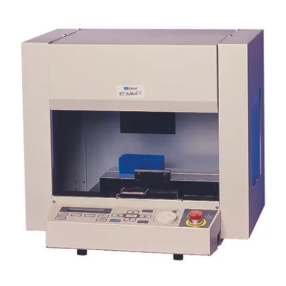
User's Manual
Thank you very much for purchasing the CAMM-3 Model PNC-
300.
• To ensure correct and safe usage with a full understanding of this
product's performance, please be sure to read through this manual
completely and store it in a safe location.
• Unauthorized copying or transferral, in whole or in part, of this
manual is prohibited.
• The contents of this operation manual and the specifications of
this product are subject to change without notice.
• The operation manual and the product have been prepared and
tested as much as possible. If you find any misprint or error,
please inform us.
• Roland DG Corp. assumes no responsibility for any direct or
indirect loss or damage which may occur through use of this
product, regardless of any failure to perform on the part of this
product.
• Roland DG Corp. assumes no responsibility for any direct or
indirect loss or damage which may occur with respect to any
article made using this product.
Advertisement
Table of Contents

Related Manuals for Roland CAMM-3 PNC-300


Summary of Contents for Roland CAMM-3 PNC-300
- Page 1 If you find any misprint or error, please inform us. • Roland DG Corp. assumes no responsibility for any direct or indirect loss or damage which may occur through use of this product, regardless of any failure to perform on the part of this product.
- Page 2 AVIS Cet appareil numérique de la classe B respecte toutes les exigences du Règlement sur le matériel brouilleur du Canada. ROLAND DG CORPORATION 1-6-4 Shinmiyakoda, Hamamatsu-shi, Shizuoka-ken, JAPAN 431-2103 MODEL NAME : See the MODEL given on the rating plate.
-
Page 3: Table Of Contents
Table of Contents How to Read This Manual ......................Typographic Conventions ......................To Ensure Safe Use ......................Part 1 Startup 1. Checking the Accessories ........................1 2. Part Names and Functions ......................... 2 3. Power Cord and Computer Connections ..................4 Vacuum Cleaner Connection ........................ -
Page 4: How To Read This Manual
Microsoft ® Corporation in the United States and/or other countries. i486 and Pentium are registered trademarks of Intel Corporation in the United States. IBM is a registered trademark of International Business Corporation. Copyright © 1994–2000 Roland DG Corporaion... -
Page 5: Typographic Conventions
Typographic Conventions This manual uses certain typographic symbols, outlined below. This indicates a point requiring particular care to ensure safe use of the product. : Failure to heed this message will result in serious injury or death. : Failure to heed this message may result in serious injury or death. -
Page 6: To Ensure Safe Use
To Ensure Safe Use Do not disassemble or remodel the Do not operate if a transparent cover machine. is cracked or broken. If the safety device is removed, the spindle If the transparent cover at the front or the side rotates while the cover is open, which is very of the unit is cracked, contact a service agent dangerous. - Page 7 Do not install in an unstable or high Do not block the ventilation holes. location. Do not installation the machine on the edge of a Blocking the ventilation holes at the rear of the table, or it may fall. unit may prevent heat radiation and cause fire. Handle the power cord with care.
- Page 8 About the Labels Affixed to the Unit These labels are affixed to the body of this product. The following figure describes the location and content of these messages. Please use a vacuum cleaner to remove cutting dust. Do not use any blower like airbrush. Otherwise, dust spread in the air may harm your health or damage this machine.
- Page 9 To Ensure Correct Use Fasten the tool and material securely in Do not operate beyond capacity or subject the place. tool to undue force. The tool may break. If machining operation beyond capacity is started inadvertently, immediately press the EMERGENCY STOP switch.
- Page 10 - MEMO -...
-
Page 11: Part 1 Startup
Machine vice (for chip-cleaning) 10 mm (0.3937") 6 mm 6 mm (0.2362") (0.2362") 10 mm 19 mm 24 mm (0.75") (0.94") (0.39") 60 mm (2-3/8") Straight end mill Wrenches Motor brushes User's manual Workpiece Power cord Roland Software Package CD-ROM... -
Page 12: Part Names And Functions
2. Part Names and Functions Cover Head Opening the cover during cutting This moves the spindle (cutting tool) up results in an emergency stop. Any and down). The head performs Z-axis cutting data in use becomes invalid, movement. and cutting cannot be continued. If the cover must be opened during cutting, first press the [ENTER/ PAUSE] key to pause the PNC-300,... - Page 13 Arrow keys TOOL UP key Liquid-crystal display HANDLE FUNCTION SELECT key HOME key ENTER/PAUSE Z1 key Z2 key SPINDLE TEST TOOL DOWN key JOG Handle ON/OFF key Z0 key VIEW key MENU key * A confirmation beep is produced whenever a key is pressed. Liquid-crystal display The settings and selection choices (or values) for the PNC-300 are shown on this display.
-
Page 14: Power Cord And Computer Connections
3. Power Cord and Computer Connections Use only with the power cord included with this product. Use with other than the included power cord may lead to fire or electrocution. NOTICE Ensure that the power supply voltage is within ±10% of the machine's rated voltage. Connect the cables only when the PNC-300 and the computer power sources are OFF. -
Page 15: Installing The Software
Log on to Windows as a member of the “Administrators” or “Power Users” group. For more information about groups, refer to the documentation for Windows. Switch on the computer and start Windows. Place the CD from the Roland Software Package in the CD-ROM drive. The Setup menu appears automatically. - Page 16 The Setup program starts. Follow the messages to carry out setup and finish setting up the program. When the setup for one program finishes, the setup for the next program starts. In the interval until the next setup starts, a dialog box showing the progress of processing is displayed.
- Page 17 How to use Help If you have trouble using the program or driver, see the help screens. Help contains information such as descriptions of software opera- tion, explanations of commands, and tips for using the software more effectively. From the [Help] menu, clik [Contents]. Clicking on text that is green and underlined (by a solid or dotted line) displays an explanation.
-
Page 18: Setting The Connection Parameters
5. Setting the Connection Parameters Connection with a parallel cable is called a "parallel connection," and connection with a serial cable is called a "serial connection." Make the appropriate settings on both the computer and the PNC-300 to configure the equipment for the type of connection that has been made. -
Page 19: Loading A Workpiece For Cutting
6. Loading a Workpiece for Cutting Installing the Machine Vise Machine vice A Machine vice B Tighten the screw by hand How to Secure a Workpiece in the Machine Vise Place the workpiece on the XY table, and move the Use the wrench included with the unit to secure machine vise so that it lightly touches both sides of machine vise A. -
Page 20: Examples Of Workpiece Of Loading
Examples of Workpiece Loading This section is an explanation of the cutting workpiece attachment method when a machine vice is used. If employing an alternative attachment method, fix the workpiece firmly in place using the following explanation for reference. Under the standard workpiece attachment method, a block is attached to the vice, then the workpiece is fixed to the block with double-sided adhesive tape. - Page 21 7. Cutting Tool Attachment Loosen the collet chuck. Insert the cutting tool. The cutting tool must not be inserted as far as the blade. Collet cap Tighten the collet chuck by hand to provisionally Secure the spindle motor so that it does not rotate, secure the cutting tool to the spindle motor.
-
Page 22: Cutting Tool Attachment
Changing the Collet Chuck The collet chuck included as standard equipment with the machine can hold a cutting tool with a shank that is 6 mm Shank diameter (0.24") in diameter. When using a cutting tool that has a different shank diameter, be sure to replace the collet chuck with one suited to the cutting tool's shank diameter. -
Page 23: Setting The Origin (Home Position And Z0)
8. Setting the Origin (Home Position and Z0) The PNC-300 are suitable for use with a versatile range of workpiece shapes and a wide variety of tools, so determine the standard points for cutting each time a new workpiece is set. Set the home position (origin point for X an Y axes) and Z0 (Z axis origin point). (If these points can be set with your current software, they should be set using the software.) Setting the Home Position The home position is the point that becomes the origin point in the X and Y directions. -
Page 24: Setting The Home Position
Setting the Z0 Position The Z0 position is the point that becomes the origin point in the Z directions. Usually, this point is set at the surface of the fixed workpiece. The following explains the method for setting the workpiece surface Z0 position. If "Z0_MEMORY" is off, then the Z0 position is set to the mechanically uppermost position immediately after the power is switched on. -
Page 25: Setting Z0 With The Z0 Position Sensor (Included With The Unit)
Setting Z0 with the Z0 Position Sensor (Included with the Unit) The Z0 sensor included with the unit is used to set the Z0 point on the Z0 position sensor surface of the workpiece. The Z0 sensor is placed on the location which is to serve as the Z0 point, and the Z0 point is set. - Page 26 The display changes to indicate the message shown Press the TOOL UP key to raise the cutting tool. below. Press the arrow keys to move the tool away from the Detach and remove the Z0 position sensor. top of the workpiece. Move out of the box Press the [Z0] key.
-
Page 27: Cutting Condition Setting
9. Cutting Condition Setting Before you begin the actual cutting process, the cutting conditions such as the revolution speed of the spindle motor and the feeding speed of each axis must be designated according to the quality of the workpiece and the type of tool used. There are several deciding factors to be taken into account when designating the cutting conditions. - Page 28 Press the [ ] or [ ] key to set the feed rate. Press the [ENTER] key. Setting range Make sure X- and Y-axis : 0 to 60 mm/sec that "< >" appears. Z-axis : 0 to 30 mm/sec Spindle Motor Revolution Speed Press the [MENU] key to make the following screen Press the HANDLE FUNCTION SELECT key to appear on the display.
-
Page 29: Cutting Condition Setting Examples
Cutting Condition Setting Examples The chart below contains reference examples of the appropriate cutting conditions for several types of workpiece material. In the case that the conditions are input using software or when constructing your own programs, set the cutting conditions with reference to the chart. However, because conditions differ depending on tool sharpness and workpiece hardness, cutting performance may not always be optimal when adhering to the conditions specified below. -
Page 30: Setting The Z1 And Z2 Position
10. Setting the Z1 and Z2 Position The cutting tool up position (Z2 point) and down position (Z1 point) are normally set with the software. If they cannot be set with your current software then set them manually using the keys on the switch panel. Tool Tool up position Tool down position... -
Page 31: Attaching A Brush Adapter For Chip Cleaning
11. Attaching a Brush Adapter for Chip Cleaning A commercially available vacuum cleaner is used during cutting to keep chips from flying into the box. Attaching the brush adapter included with the PNC-300 can enhance chip-cleaning performance. Before attaching the brush adapter, first clean away any chips that may be present on the mounting surface. NOTICE You should never bring floppy disks close to brush adapter, since the data on them could be... -
Page 32: Finishing
13. Finishing After cutting has been finished, detach the tool, remove the material, and clean away chips. The tool blade can cause injury to the hand even when not in motion. Press the [MENU] key to make the following screen Press the [VIEW] key for at least 0.5 seconds. -
Page 33: Part 2 User's Reference
User's Reference Cutting Area The maximum cutting area of the PNC-300 is 120 mm 100 mm 120 mm (4-11/16" 3-7/8" 4-11/16"). When converted to coordinate values, this corresponds to (x, y, z) = (12000, 10000, 12000) when the coordinate unit is 0.01 mm, or (x, y, z) = (4800, 4000, 12000) when the coordinate unit is 0.025 mm. -
Page 34: Operating Each Function
Operating Each Function Making Settings with the Liquid-crystal Display Changing to Other-language Messages on the Liquid-crystal Display Switch on the power while holding down the Press the [ ] key to move the blinking cursor (" ") to [MENU] key. "Japanese,"... -
Page 35: Performing Repeat Cutting
Performing Repeat Cutting The repeat cutting function cannot be used unless the PNC-300's memory buffer has been expanded to 1 MB. The data buffer is the place where data received from the computer is stored temporarily. (The data in the data buffer can be erased by switching off the power or executing the "BUFFER-CLEAR".) Executing the "REPEAT"... -
Page 36: Changing The Feed Rate Or Spindle Speed During Cutting
Changing the Feed Rate or Spindle Speed During Cutting The feed rate and spindle rotating speed set by the software can be changed while cutting is in progress. This is done by first pausing the PNC-300 during cutting, then changing the feed rate or spindle speed. However, if the computer subsequently sends a command to change the feed rate or spindle speed, the setting will change as specified by the new command. - Page 37 Changing the Spindle Speed Press the [ENTER/PAUSE] key while cutting is in Press the [MENU] key to make the following screen progress. One cutting step is performed, after which appear on the display. operation stops. The display changes to show the following message.
-
Page 38: Stopping The Cutting Process
Stopping the Cutting Process In the case that you begin cutting and then find that you have sent the wrong cutting data, perform the following operation. Press the [ENTER/PAUSE] key while cutting is in Use the software to stop data output. progress. -
Page 39: Explanation Of The Display Menus
Explanation of the Display Menus This shows the current position of the tool (in coordinates) and the spindle speed. The coordinate values indicate the home position as the origin point on the X and Y axes, and the Z0 point as the origin point on the Z axis. "RPM" is an abbreviations for "revolutions per minute."... - Page 40 "REVOLUTION" Default : ON When set to "OFF," cutting can be performed without rotating the spindle. "OVER_AREA" Default : CONTINUE This selects the action when the tool returns from a coordinate outside the cutting range to a coordinate inside the range. (The tool cannot actually be moved outside the cutting range, but the PNC-300's internal processing handles this as if it had.) "CONTINUE"...
- Page 41 "COMMAND" Default : AUTO This selects the instruction system for data sent from the computer. When set to "AUTO," the instruction system is determined automatically. If automatic determina- tion is not made correctly, find out what instruction system the application software (or driver software) uses for data that is sent, and change this setting to "MODE1"...
-
Page 42: Maintenance
Maintenance NOTICE When cleaning the PNC-300, make sure that the main unit's power OFF. Cleaning the Main Unit When the main unit becomes dirty, use a dry cloth to wipe it. Cleaning After Operation After cutting work is completed, use a vacuum cleaner to clean the PNC-300 main unit and the surrounding area of cutting dust. - Page 43 Included with the PNC-300 are two motor brushes (one set) which can be used the first time the motor brushes are replaced. Contact Roland DG Corp. when replacing for the second time or after.
- Page 44 Display of Spindle Rotation Time The PNC-300 has a function for the displaying the total rotation time of the spindle. The service life of the unit can be extended by carrying out periodic inspection. As a general guide, this inspection should be performed after every 500 hours of use. Press the [MENU] key to make the following screen Press the [ ] key to move the blinking cursor ("...
-
Page 45: Troubleshooting
Troubleshooting When the PNC-300 does not work... Is the cover open? The PNC-300 will not operate when the cover is open. Close the cover and try again. Is operation paused? Cancel the paused state. For details, see "Canceling the Paused State to Resume Cutting". -
Page 46: Error Messages
Error Messages An error message will appear if incoming data has any of the errors listed in table. Since the error is shown in the display for informational purposes, the data transfer continues and you are allowed to perform the next operation. To get the error message to go away, press the [MENU] key. -
Page 47: Other Messages
Other Messages Besides error messages related to commands or communication parameters, the following messages may also appear on the display. Message Meaning This message appears if repeat cutting is attempted when the cutting data exceeds 1 MB. The data cannot all fit in the PNC-300's data buffer, so repeat cutting cannot be performed. The display can be cleared by pressing the [MENU] key. -
Page 48: List Of Camm-Gl I Instructions
* 3 : -(2 -1)°—+(2 -1)° A "CAMM-GL I Programmer's Manual" is available for separate purchase for those wishing to create their own programs for this machine. For further information, please contact the nearest Roland DG Corp. dealer or distributor. mode1 Instruction Com. - Page 49 mode2 Instruction Com. Format Parameter Range [Default] Circle CI r (, Ød) ; Radius Ød Chord tolerance * 3 [5°] Character Plot CP nx, ny ; Number of character in X or Y-axis nx, ny CP ; direction Standard Character Set CS n;...
-
Page 50: Device Control Instructions
mode1, mode2 common instruction Instruction Com. Format Parameter Range [Default] Dwell !DW t [terminator] Dwell time 0—32767 [0] Input Home Position !IO x, y [terminator] x, y Coordinates of home position (designate by machine coordinate) Motor Control !MC n [terminator] Motor ON/OFF switching -32768—32767 [motor ON] !MC [terminator]... - Page 51 Instruction Format Parameter Range ([ ] is default) Explanation ESC .I [ESC].I<P1>;<P2>; P1 : Limit of the remaining 0—15358(byte) [80(byte)] Used for performing the Xon/Xoff handshake and the Set Xon/Xoff <P3> ;••••••••;<P12>: buffer capacity (for Xon/Xoff) ENQ/ACK handshake mode 2. Handshake and ENQ/ The number of data block The [ESC].I instruction with no parameter performs a...
-
Page 52: Display Menus Flowchart
Display Menus Flowchart Switch on the power while holding POWER ON down the [MENU] key to select the language used for the display, then press Press to go to (1) to move the "*" to "X" or "Y," then press to move the "*"... - Page 53 Menu Flowchart When Paused Press the [ENTER/PAUSE] key while cutting is in progress. COVER OPENED COVER CLOSED...
-
Page 54: Specifications
ø6 collet chuck, collet cap (these are installed on the unit), straight end mill (ø6), workpiece Z0 position sensor, motor brushes : 2, wrenches : 3 (10 mm, 19 mm, 24 mm each) machine vice, power cord, user's manual, Roland Software Package CD-ROM • Hardware Specification •... - Page 55 Parallel connector (in compliance with Serial connector (RS-232C) specifications of Centronics) Signal Terminal Signal Signal Terminal Signal Pin Connection Pin Connection number number number number number number HIGH** HIGH* HIGH* HIGH* BUSY Ω 3.3K Ω STROBE...
-
Page 56: Index
Index <D> “0.01 mm” ................30 “0.025mm” ................30 “DATA” ..................31 data bits ................8, 31 <A> device control instructions ..........40, 41 accessories ................. 1 display menus ............29—31, 42 application software ..............21 display menus flowchart ............42 arrow key ................... - Page 57 “Z0” ................... 14, 30 “REVOLUTION TIME” ........... 31, 34 “Z0_MEMORY” ................ 30 “REVOLUTION” ..............30 Z1 key .................. 3, 20 Roland Software Package CD-ROM ........1, 5 Z1 position ................20 “RPM” ..................29 “Z1” ................... 20, 29 RS-232C ..................4 Z2 key ..................
- Page 58 - MEMO -...
- Page 60 The enclosed Roland product is a single user version.