Table of Contents
Advertisement
Quick Links
Advertisement
Table of Contents

Related Manuals for DURKOPP ADLER 745-35-10 S


Summary of Contents for DURKOPP ADLER 745-35-10 S
- Page 1 745-35-10 S 745-35-10 A Operating Instructions...
- Page 2 IMPORTANT READ CAREFULLY BEFORE USE KEEP FOR FUTURE REFERENCE All rights reserved. Property of Dürkopp Adler AG and protected by copyright. Any reuse of these contents, includ- ing extracts, is prohibited without the prior written approval of Dürkopp Adler AG. Copyright ©...
-
Page 3: Table Of Contents
4.14 Stacker control................35 4.15 Corner knife station ..............36 4.15.1 Swiveling corner knife station in/out 745-35-10 S....... 36 4.15.2 Swiveling corner knife station in/out 745-35-10 A....... 37 4.15.3 Adjusting corner knife ..............38 4.16 Setting the reference position ............. 39 4.17... - Page 4 Troubleshooting ..............233 10.1 Customer Service ..............233 10.2 Messages of the software............233 Technical data................. 245 Appendix ................. 247 12.1 Wiring diagram 745-35-10 S............. 247 12.2 Wiring diagram 745-35-10 A............. 259 Operating Instructions 745-35-10 S/745-35-10 A - 03.0 - 04/2017...
-
Page 5: About These Instructions
Specifies proper setting. Disturbances Specifies the disturbances that can occur due to an incorrect setting. Cover Specifies which covers must be removed in order to access the compo- nents to be set. Operating Instructions 745-35-10 S/745-35-10 A - 03.0 - 04/2017... - Page 6 Safety ( p. 7). If no other clear location information is used in a figure, indications of right Location information or left are always from the user's point of view. Operating Instructions 745-35-10 S/745-35-10 A - 03.0 - 04/2017...
-
Page 7: Other Documents
Leave machines, equipment and packaging material in the condition in which they were found when the damage was discovered. This will ensure any claims against the transport company. Report all other complaints to Dürkopp Adler immediately after receiving the product. Operating Instructions 745-35-10 S/745-35-10 A - 03.0 - 04/2017... - Page 8 About these instructions Operating Instructions 745-35-10 S/745-35-10 A - 03.0 - 04/2017...
-
Page 9: Safety
• set up the machine • carry out maintenance work and repairs • perform work on electrical equipment Only authorized persons may work on the machine and must first have un- derstood these instructions. Operating Instructions 745-35-10 S/745-35-10 A - 03.0 - 04/2017... -
Page 10: Signal Words And Symbols Used In Warnings
If ignored, environmental damage can result NOTICE (without hazard symbol) If ignored, property damage can result The following symbols indicate the type of danger to personnel: Symbols Symbol Type of danger General Electric shock Operating Instructions 745-35-10 S/745-35-10 A - 03.0 - 04/2017... - Page 11 Consequences of non-compliance. Measures for avoiding the danger. This is what a warning looks like for a hazard that could result in moderate or minor injury if the warning is ignored. Operating Instructions 745-35-10 S/745-35-10 A - 03.0 - 04/2017...
- Page 12 Type and source of danger! Consequences of non-compliance. Measures for avoiding the danger. This is what a warning looks like for a hazard that could result in property damage if ignored. Operating Instructions 745-35-10 S/745-35-10 A - 03.0 - 04/2017...
-
Page 13: Machine Description
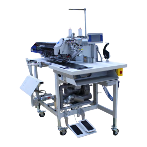
Machine description Machine description 3.1 Components of the machine 745-35-10 S Fig. 1: Components of the machine 745-35-10 S (1) ② ① (1) - Pedal (2) - Control panel OP7000 Operating Instructions 745-35-10 S/745-35-10 A - 03.0 - 04/2017... - Page 14 Machine description Fig. 2: Components of the machine 745-35-10 S (2) ③ ⑥ ④ ⑤ (3) - External winder (5) - Control DAC comfort (4) - Compressed air gun (6) - Compressed air maintenance unit Operating Instructions 745-35-10 S/745-35-10 A - 03.0 - 04/2017...
-
Page 15: Components Of The Machine 745-35-10 A
Fig. 3: Components of the machine 745-35-10 A (1) ① ⑤ ② ④ ③ (1) - Roll-off device (4) - Tape feeder (2) - Throw-over stacker (5) - Control panel OP7000 (additional equipment) (3) - Pedal Operating Instructions 745-35-10 S/745-35-10 A - 03.0 - 04/2017... -
Page 16: Proper Use
The seam must be completed with a thread that satisfies the requirements of the specific application at hand. The machine is intended for industrial use. Operating Instructions 745-35-10 S/745-35-10 A - 03.0 - 04/2017... -
Page 17: Declaration Of Conformity
Follow all instructions provided. 3.4 Declaration of Conformity The machine complies with European regulations ensuring health, safety, and environmental protection as specified in the declaration of conformity or in the declaration of incorporation. Operating Instructions 745-35-10 S/745-35-10 A - 03.0 - 04/2017... - Page 18 Machine description Operating Instructions 745-35-10 S/745-35-10 A - 03.0 - 04/2017...
-
Page 19: Operation
Fig. 5: Switching on the machine To switch on the machine: 1. Turn the main switch from position 0 to position I. The machine starts up. The control panel starts up. Operating Instructions 745-35-10 S/745-35-10 A - 03.0 - 04/2017... -
Page 20: Swiveling The Folding Station To The Side
4.4 Locking the folding station in place NOTICE Property damage may occur! If not fully swiveled down, the folding station can damage the machine when sewing starts. Lock the folding station in place inside the locking mechanism. Operating Instructions 745-35-10 S/745-35-10 A - 03.0 - 04/2017... - Page 21 (1) - Locking mechanism (2) - Folding station To lock the folding station in place: 1. Swivel down the folding station (2). 2. Lock the folding station in place inside the locking mechanism (1). Operating Instructions 745-35-10 S/745-35-10 A - 03.0 - 04/2017...
-
Page 22: Changing Needles
2. Loosen the screws (3) and remove the needles from the needle holders (1). 3. Insert the new needle into the hole of the needle holder (1) until it reaches the stop. Operating Instructions 745-35-10 S/745-35-10 A - 03.0 - 04/2017... -
Page 23: Threading The Needle Thread
5. Swivel the folding station to the side ( p. 18). 6. Fit the thread reel on the thread reel holder (1). 7. Feed the thread from the thread reel through the hole (2) of the thread reel holder. Operating Instructions 745-35-10 S/745-35-10 A - 03.0 - 04/2017... - Page 24 2. Fit the thread reel on the thread reel holder. 3. Feed the thread from the thread reel through the hole (2) of the thread reel holder. 4. Insert the thread through the guide (1). Operating Instructions 745-35-10 S/745-35-10 A - 03.0 - 04/2017...
- Page 25 13. Insert the thread through the guide (3). 14. Feed the thread through the needle thread monitor (12). 15. Insert the thread through the guide (5). Feed the thread into the right needle. Operating Instructions 745-35-10 S/745-35-10 A - 03.0 - 04/2017...
-
Page 26: Winding The Bobbin Thread
4. Insert the thread in a wavelike manner through the guide (6). 5. Feed the thread counterclockwise through the bobbin thread tensioner (2). 6. Wind some of the thread counterclockwise into the front and rear reserve grooves of the bobbin hub (4). Operating Instructions 745-35-10 S/745-35-10 A - 03.0 - 04/2017... -
Page 27: Replacing The Bobbin Thread Reels
3. Raise the fabric sliding plate and swivel it to the left ( p. 29). 4. Lift the bobbin case upper section (1). The bobbin case retainer (2) will be lifted as well. Operating Instructions 745-35-10 S/745-35-10 A - 03.0 - 04/2017... -
Page 28: Thread Tension
If the tension of needle thread and bobbin thread is identical, the thread interlacing lies in the middle of the sewing material. Set the needle thread tension so that the desired seam pattern is achieved with the lowest possible tension. Operating Instructions 745-35-10 S/745-35-10 A - 03.0 - 04/2017... -
Page 29: Setting The Needle Thread Tension
2. Adjust the tension of the needle threads using knurled nut (2) (right needle thread) and knurled nut (1) (left needle thread). • Increase the needle thread tension: Turn clockwise • Reduce the needle thread tension: Turn counterclockwise Operating Instructions 745-35-10 S/745-35-10 A - 03.0 - 04/2017... -
Page 30: Setting The Bobbin Thread Tension
• Increase the bobbin thread tension: Turn clockwise • Reduce the bobbin thread tension: Turn counterclockwise With the bobbin inserted and the bobbin thread threaded through the throat plate a uniform and easy pull-off must be assured. Operating Instructions 745-35-10 S/745-35-10 A - 03.0 - 04/2017... -
Page 31: Sliding Back The Hood And Removing The Fabric Sliding Plate
2. Loosen the screw (2) on the hood (1). 3. Slide the hood (1) to the left. You can now access the transport clamps. 4. Slide the hood (1) back to the right until it locks audibly into place. Operating Instructions 745-35-10 S/745-35-10 A - 03.0 - 04/2017... - Page 32 1. Lift the fabric sliding plate (3) in the area of the tabletop recess (4) and swing it out to the left. 2. Lift the fabric sliding plate completely at the pin (5). Operating Instructions 745-35-10 S/745-35-10 A - 03.0 - 04/2017...
-
Page 33: Swiveling Up The Machine Head
1. Remove the hood (1). To do so, lift the hood (1) up at the front to release the lock. 2. Carefully lift the hood (1) up and off. 3. Swivel the folding station out by 90° ( p. 18). 4. Swivel the locking lever (3) up. Operating Instructions 745-35-10 S/745-35-10 A - 03.0 - 04/2017... -
Page 34: Swiveling Down The Machine Head
Hold on to the machine head until it is completely at rest when lowered. Fig. 22: Swiveling down the machine head (1) ③ ① ② (1) - Hood (3) - Locking lever (2) - Head cover Operating Instructions 745-35-10 S/745-35-10 A - 03.0 - 04/2017... -
Page 35: Remaining Thread Monitor
(1) and (2) monitors the left and the right bobbin thread reel. Fig. 24: Remaining thread monitor ① ② ③ (1) - Light barrier 1 (3) - Reflecting surface (2) - Light barrier 2 Operating Instructions 745-35-10 S/745-35-10 A - 03.0 - 04/2017... - Page 36 1. Switch off the main switch. 2. Clean the lenses of the light barriers with a soft cloth every time you change the bobbin. 3. Switch on the main switch. 4. Start a new sewing process. Operating Instructions 745-35-10 S/745-35-10 A - 03.0 - 04/2017...
-
Page 37: Stacker Control
Do not reach into the movement area of the transport carriage when removing the workpiece. Do not clean the lenses of the light barriers unless the sewing unit is switched off. Operating Instructions 745-35-10 S/745-35-10 A - 03.0 - 04/2017... -
Page 38: Corner Knife Station
Unless swiveled in all the way, the corner knife station can damage the machine. When swiveled in, the corner knife station engages audibly. Fig. 26: Swiveling corner knife station in/out 745-35-10 S ① (1) - Corner knife station To swivel the corner knife station in and out: 1. -
Page 39: Swiveling Corner Knife Station In/Out 745-35-10 A
1. Swivel the corner knife station (1) to the left. The knives are accessible for setup and service work. 2. Swivel down and engage the corner knife station under the sewing unit. Operating Instructions 745-35-10 S/745-35-10 A - 03.0 - 04/2017... -
Page 40: Adjusting Corner Knife
5. Set the angle at the other pair of knives accordingly. 6. Swivel in the corner knife station. Height of the corner knives The height of the corner knives cannot be adjusted. The knives always cut through completely. Operating Instructions 745-35-10 S/745-35-10 A - 03.0 - 04/2017... -
Page 41: Setting The Reference Position
Operation Position of the adjustable knife block (745-35-10 S only) Fig. 29: Position of the adjustable knife block (745-35-10 S only) ⑤ ⑥ (5) - Scale (6) - Clamping lever The position of the adjustable knife block corresponds to the seam length that has been set in the global parameters. -
Page 42: Performing A Quick Stop
(2) - Flap projection max. 20 mm. (3) - Flap NA: Seam projection (4) - Piping strip a, b: Material passage at the folder (5) - Flap projection max. 20 mm/40 mm Operating Instructions 745-35-10 S/745-35-10 A - 03.0 - 04/2017... - Page 43 20 mm beyond seam beginning and seam end. The length of the piping strip is calculated as follows: Piping strip length = sewing length + 2 x 20 mm Operating Instructions 745-35-10 S/745-35-10 A - 03.0 - 04/2017...
-
Page 44: Folder Monitor (745-35-10 A Only)
To correct a faulty transport clamp setup: 1. Press the left pedal back. The error message is canceled. 2. Select another seam program. 3. Change the setting in the seam program. Operating Instructions 745-35-10 S/745-35-10 A - 03.0 - 04/2017... -
Page 45: Additional Equipment
3. Press the left pedal forwards. The downholder (1) lowers and clamps the hind trousers in their position. 4. Smooth out the clamped hind trousers laterally and to the front. Operating Instructions 745-35-10 S/745-35-10 A - 03.0 - 04/2017... -
Page 46: Waistband Clamp (745-35-10 A Only)
5. Press the left pedal forwards. Downholder (1) and waistband clamp (3) lower and clamp the hind trousers in their position. 6. Smooth out the clamped hind trousers laterally and to the front. Operating Instructions 745-35-10 S/745-35-10 A - 03.0 - 04/2017... -
Page 47: Roll-Off Device (745-35-10 A Only)
1. Activate the roll-off on the control panel in menu item Machine param- eters, ( p. 134). The parameter signals to the control that the sewing unit is equipped with an roll-off device. Operating Instructions 745-35-10 S/745-35-10 A - 03.0 - 04/2017... -
Page 48: Blow-Out Device
1. Switch on the blow-out device (1) in the menu item Machine parame- ters, ( p. 134). 2. Set blowing mode ( p. 130). Information The blast pipe continues to blow until the light barrier used for stacker con- trol is clear. Operating Instructions 745-35-10 S/745-35-10 A - 03.0 - 04/2017... -
Page 49: Bundle Clamp
(3) - Bundle clamp (2) - Pedal (4) - Table extension To operate the bundle clamp: 1. Press the pedal (2) and hold it down. The bundle clamp (3) opens. Operating Instructions 745-35-10 S/745-35-10 A - 03.0 - 04/2017... -
Page 50: Tape Feeder With Automatic Cutter (745-35-10 A Only)
3. Insert the adapter (3) into a new tape roll on the left and the right. 4. Slip the adjusting ring (2) back onto the shaft. 5. Tighten the screw (1) again. Operating Instructions 745-35-10 S/745-35-10 A - 03.0 - 04/2017... - Page 51 7. Swivel the fabric sliding plate (8) aside ( p. 29). 8. Press the slide (10) to the rear and lift off the cover. 9. Press the button. The tape brake is released, and the reinforcement strip advances continuously. Operating Instructions 745-35-10 S/745-35-10 A - 03.0 - 04/2017...
- Page 52 The reinforcement strip is cut to the correct length. Information The tape projection at seam beginning and seam end can be set in the menu item Pocket parameters ( p. 120). Operating Instructions 745-35-10 S/745-35-10 A - 03.0 - 04/2017...
-
Page 53: Vacuum Device (745-35-10 A)
2. Turn on the switch (1) at the control box of the vacuum device. 3. Switch on the vacuum device on the control panel in the menu item Pocket parameters, ( p. 127). Operating Instructions 745-35-10 S/745-35-10 A - 03.0 - 04/2017... -
Page 54: Sewing
• Press the pedal back. The last step of the positioning sequence is canceled. The workpiece can be positioned again. 3. Press the pedal forwards. The sewing procedure is started. Operating Instructions 745-35-10 S/745-35-10 A - 03.0 - 04/2017... - Page 55 This section describes how to adjust and align the positioning aids (e.g. positioning marks, marking lamps, stops, etc.). Positioning and starting sewing process This item includes a list of the individual positioning steps illustrated by typical examples. Operating Instructions 745-35-10 S/745-35-10 A - 03.0 - 04/2017...
-
Page 56: Working Method A (Production Of Trousers)
EXAMPLE: Hind trousers without flap, with underlaid pocket bag (745-35-10 S) Fig. 44: Hind trousers without flap, with underlaid pocket bag 745-35-10 S (1) ① (1) - Pocket bag clamp To sew a pair of hind trousers without flap and with underlaid pocket bag: 1. - Page 57 Operation Fig. 45: Hind trousers without flap, with underlaid pocket bag 745-35-10 S (2) ② ③ (2) - Downholder (3) - Marking lamps 3. Line up the hind trousers with the laser markings (3). 4. Tap the pedal / left pedal.
- Page 58 Operation Fig. 46: Hind trousers without flap, with underlaid pocket bag 745-35-10 S (3) ⑥ ⑤ ④ (4) - Front edges (6) - Folder (5) - Piping strip 7. Tap the pedal / left pedal. The transport clamps move to the front and lower onto the workpiece.
- Page 59 ⑤ (2) - Markings (4) - Waistband clamp (3) - Downholder (5) - Rear positioning point 3. Position the hind trousers at the rear positioning point (5) and the markings (2) Operating Instructions 745-35-10 S/745-35-10 A - 03.0 - 04/2017...
- Page 60 (6). The alignment of the different types of piping on the transport clamps is described in more detail below. 8. Tap the pedal. The folder (8) lowers. 9. Tap the pedal again. The sewing process starts. Operating Instructions 745-35-10 S/745-35-10 A - 03.0 - 04/2017...
- Page 61 Flap clamp right, which is available as additional equipment. The edges (9) and (10) must be sufficiently seized by the needle, but must not be cut by the middle knife. Operating Instructions 745-35-10 S/745-35-10 A - 03.0 - 04/2017...
- Page 62 Depending on the area of application, the following additional equipment is required for the simultaneous sewing-in of flaps or other additional parts: • Production of trousers: Flap clamp right • Production of jackets: Flap clamp left Operating Instructions 745-35-10 S/745-35-10 A - 03.0 - 04/2017...
- Page 63 The flap clamp (2) delivers the unmachined part (1). It has to be machined as a shaped guide that corresponds to the flap used. When sewing in flaps, the seam beginning and seam end are recognized by the light barrier. Operating Instructions 745-35-10 S/745-35-10 A - 03.0 - 04/2017...
- Page 64 Correction of seam beginning and seam end To correct seam beginning (NA) and seam end (NE) when sewing with light barrier: 1. Select pocket program Correction light barrier, see ( p. 107). Operating Instructions 745-35-10 S/745-35-10 A - 03.0 - 04/2017...
-
Page 65: Working Method A (Production Of Jackets)
(rear positioning point selected) and a pocket program for right jacket front parts (front positioning point selected). This will save you the trouble of al- tering the pocket program on the start screen when changing between left and right jacket front parts. Operating Instructions 745-35-10 S/745-35-10 A - 03.0 - 04/2017... - Page 66 If the flap (10) is positioned outside the dotted lines (outside of the sewing area), the function sequence will be interrupted. The display shows the fol- lowing error messages: Info 9721 Info 9722 Operating Instructions 745-35-10 S/745-35-10 A - 03.0 - 04/2017...
- Page 67 (9) - Light spot (5) - Stop (10) - Flap (6) - Light spot (11) - Side seam Fig. 58: Positioning and starting sewing process (2) ⑫ (12) - Pocket opening Operating Instructions 745-35-10 S/745-35-10 A - 03.0 - 04/2017...
- Page 68 To make positioning corrections: 1. Press the pedal back. The transport clamps lift. 2. Press the pedal back again. The transport carriage returns to its waiting position. Operating Instructions 745-35-10 S/745-35-10 A - 03.0 - 04/2017...
- Page 69 Fig. 60: Positioning and starting sewing process (4) ⑦ ⑮ ⑩ ⑱ ⑯ ⑰ ⑤ (5) - Stop (16) - Flap clamp (7) - Stop (17) - Folder (10) - Flap (18) - Flap clamp (15) - Stop Operating Instructions 745-35-10 S/745-35-10 A - 03.0 - 04/2017...
- Page 70 ( p. 127). They can also close in a different order. 3. Press the pedal forwards. Flap clamp (16) closes. 4. Press the pedal forwards. Flap clamp (18) closes. The sewing process starts. Operating Instructions 745-35-10 S/745-35-10 A - 03.0 - 04/2017...
-
Page 71: Programming
p. 138 1.17 Select flap clamps p. 143 1.18 Set light barrier scan p. 156 1.22 Corner knife device (745-35-10 A only) p. 142 1.23 Set pedal operation Operating Instructions 745-35-10 S/745-35-10 A - 03.0 - 04/2017... - Page 72 3.4 External devices p. 174 3.5 Multi test I/O p. 182 3.6 Sewing motor test p. 173 3.7 Error messages p. 179 RAM test p. 181 ROM test Operating Instructions 745-35-10 S/745-35-10 A - 03.0 - 04/2017...
- Page 73 5.1.4.9 Select flap right/left p. 101 5.1.4.10 Select positioning points p. 101 5.1.4.11 Set stitch length main seam p. 105 5.1.4.12 Set flap scan p. 107 5.1.5 Correction light barrier Operating Instructions 745-35-10 S/745-35-10 A - 03.0 - 04/2017...
- Page 74 p. 127 5.1.13.2 Vacuum On/Off p. 127 5.1.13.3 Downholder On/Off p. 128 5.1.13.4 Select downholder mode (745-35-10 A only) p. 130 5.1.13.5 Set blowing mode (745-35-10 A only) Operating Instructions 745-35-10 S/745-35-10 A - 03.0 - 04/2017...
- Page 75 p. 185 8.1 Data transfer to USB p. 187 8.2 Data transfer from USB 9.0 Init. parameters p. 189 Initialize machine configuration p. 189 Initialize global parameters Operating Instructions 745-35-10 S/745-35-10 A - 03.0 - 04/2017...
- Page 76 Initialize all sequences p. 189 Initialize RAM 10.0 Maintenance p. 191 10.3 Display software version p. 191 10.4 Enter date and time p. 196 Updating machine software Operating Instructions 745-35-10 S/745-35-10 A - 03.0 - 04/2017...
- Page 77 The user must enable the machine for use after the display of the welcome message goes out. Follow the instructions shown on the display for this purpose: To switch on the machine: 1. Press the pedal. The control panel is enabled. Operating Instructions 745-35-10 S/745-35-10 A - 03.0 - 04/2017...
- Page 78 p. 81 Edit seam sequence ④ p. 80 Piece counter ⑤ Display of selected seam pattern • the display changes with the setting of the pocket program (with/without flap). Operating Instructions 745-35-10 S/745-35-10 A - 03.0 - 04/2017...
- Page 79 2. Press the desired button for which you wish to display a Help text. The selected button and a Help text are displayed. 3. Press on the Help text. The Help text disappears. Operating Instructions 745-35-10 S/745-35-10 A - 03.0 - 04/2017...
- Page 80 Home button • saves the settings in the menu • Return to the start screen Return button • saves the settings in the menu • Return to next higher menu level Operating Instructions 745-35-10 S/745-35-10 A - 03.0 - 04/2017...
- Page 81 To enter a negative value on the numeric keypad: 1. Enter the desired value. 2. Press the +/- button. The value is given a - sign and becomes negative. 3. Confirm with OK. Operating Instructions 745-35-10 S/745-35-10 A - 03.0 - 04/2017...
- Page 82 The display switches to Edit mode. 2. Use the numeric keypad to set the desired number of pieces (0-10000). 3. Confirm with OK. The display returns to the start screen. Operating Instructions 745-35-10 S/745-35-10 A - 03.0 - 04/2017...
- Page 83 Varies with the programming Selected seam sequence ② Varies with the programming Display of pocket programs assigned to the seam sequence ③ Call up additional seam sequences • in steps of 5 Operating Instructions 745-35-10 S/745-35-10 A - 03.0 - 04/2017...
- Page 84 ⑨ ⑬ ⑩ ⑪ ⑫ (9) - Seam sequence template (12) - Help (10) - Seam sequence to be created (13) - Delete pocket program (11) - Available pocket program slot Operating Instructions 745-35-10 S/745-35-10 A - 03.0 - 04/2017...
- Page 85 The pocket programs will be stored in the seam sequence in the order in which they were added to the seam sequence. Operating Instructions 745-35-10 S/745-35-10 A - 03.0 - 04/2017...
- Page 86 Important The preset program is copied to the selected pocket program slot, deleting the previous program. 5. Select additional preset programs as described above and add them to the sequence. Operating Instructions 745-35-10 S/745-35-10 A - 03.0 - 04/2017...
- Page 87 OR tap on the trash to delete all pocket programs. The pocket programs are deleted from the sequence. 2. Press the button (1). The display switches to Select program. Operating Instructions 745-35-10 S/745-35-10 A - 03.0 - 04/2017...
- Page 88 The order in which they are selected corresponds to the order of the programs in the seam sequence. To scroll up and down the list of pocket programs, press the buttons Operating Instructions 745-35-10 S/745-35-10 A - 03.0 - 04/2017...
- Page 89 The display switches to Select source of sequence. Fig. 71: Changing the seam sequence template (2) Display of the sequence Selectable content sequences The destination sequence is grayed out and cannot be selected. Operating Instructions 745-35-10 S/745-35-10 A - 03.0 - 04/2017...
- Page 90 4. Use Drag and Drop to drag any pocket programs you do not need from the sequence to be created (3) to the trash OR tap on the trash to delete all pocket programs. The pocket programs are deleted from the sequence. Operating Instructions 745-35-10 S/745-35-10 A - 03.0 - 04/2017...
- Page 91 The display returns to Overview of sequences. 7. Press the button to save the setting and return to the start screen. You can start sewing with the new seam sequence right away. Operating Instructions 745-35-10 S/745-35-10 A - 03.0 - 04/2017...
- Page 92 Fig. 75: Naming a seam sequence (2) 2. Enter the desired sequence name. You can enter up to 18 characters. Every sequence must be given a name. 3. Confirm with OK. Operating Instructions 745-35-10 S/745-35-10 A - 03.0 - 04/2017...
- Page 93 3. Press the desired seam sequence. The selected seam sequence is highlighted with a bold frame and the color orange (1). 4. Press the button. The display switches to Copy sequence. Operating Instructions 745-35-10 S/745-35-10 A - 03.0 - 04/2017...
- Page 94 To scroll up and down the list of sequences, press the buttons OR drag the bar up or down. Information Cancel the selection by pressing the same sequence again. 6. Press the desired seam sequence. The display shows an info field. Operating Instructions 745-35-10 S/745-35-10 A - 03.0 - 04/2017...
- Page 95 Fig. 79: Activating a pocket program from the seam sequence ① ② (1) - Pocket programs in sequence (2) - selected pocket program Operating Instructions 745-35-10 S/745-35-10 A - 03.0 - 04/2017...
- Page 96 To activate the automatic seam sequence: 1. Press the button. The start screen shows arrows between the seam sequences. The arrows indicate that the automatic seam sequence has been activated. Operating Instructions 745-35-10 S/745-35-10 A - 03.0 - 04/2017...
- Page 97 Select pocket program p. 97 Enter name of pocket program p. 98 Copy pocket program p. 98 Create seam program p. 100 Correction light barrier p. 107 Operating Instructions 745-35-10 S/745-35-10 A - 03.0 - 04/2017...
- Page 98 Program loading process p. 127 Stacker/smoother/blow-off/roll-off p. 134 Tape trimming On/Off (745-35-10 A only) Reset seam program 2. Press the desired button. The user interface for setting the desired item is displayed. Operating Instructions 745-35-10 S/745-35-10 A - 03.0 - 04/2017...
- Page 99 ( p. 81). If the pocket program has already been copied to the selected seam sequence, you can activate it in the seam sequence ( p. 93). Operating Instructions 745-35-10 S/745-35-10 A - 03.0 - 04/2017...
- Page 100 The display switches to Copy pocket program. Fig. 82: Copying a pocket program (1) Symbols Meaning Select source Select destination Save settings To copy a pocket program: 1. Press the button. Operating Instructions 745-35-10 S/745-35-10 A - 03.0 - 04/2017...
- Page 101 Fig. 83: Copying a pocket program (2) 6. Confirm with OK. The message Copy was successful is displayed. 7. Confirm with OK. The display switches to the selected seam program. Operating Instructions 745-35-10 S/745-35-10 A - 03.0 - 04/2017...
- Page 102 • slanted • slanted • Set slanted pocket shape seam begin. (1 - 13 mm) Securement seam beginning left/right needle • Stitch condensing OR • Single tack OR • Double tack Operating Instructions 745-35-10 S/745-35-10 A - 03.0 - 04/2017...
- Page 103 • 100 mm - 450 mm Set stitch length main seam • 1.5 mm - 3.5 mm Set flap scan • Fixed seam length • 1 light barrier • Automatic flap scan left Reset seam program Operating Instructions 745-35-10 S/745-35-10 A - 03.0 - 04/2017...
- Page 104 Select double tack • Set stitch length for double tack at seam beginning (0.5 - 3.5 mm) • Set number of stitches for double tack at seam beginning (0 - 10) Operating Instructions 745-35-10 S/745-35-10 A - 03.0 - 04/2017...
- Page 105 ( p. 102). Set securement seam end left needle The display switches to Securement seam end left needle. Fig. 86: Set securement seam end left needle Operating Instructions 745-35-10 S/745-35-10 A - 03.0 - 04/2017...
- Page 106 2. Enter the desired value using the numeric keypad. The user interface for setting the desired item is displayed. Information If the seam pattern is straight, you only have to set the left seam securement. Operating Instructions 745-35-10 S/745-35-10 A - 03.0 - 04/2017...
- Page 107 Set maximum flap length Not available unless Activate flap scan has been selected Activate automatic flap scan left • Light barrier must be activated in the Machine configuration p. 143 Operating Instructions 745-35-10 S/745-35-10 A - 03.0 - 04/2017...
- Page 108 Fig. 88: Activating the flap (2) ② ① ② ③ (1) - Quick access corner knife correction (3) - Display of flap (2) - Quick access flap correction Operating Instructions 745-35-10 S/745-35-10 A - 03.0 - 04/2017...
- Page 109 • -20 mm - 20 mm To make a correction to the light barrier: 1. Press the desired button. 2. Enter the desired value using the numeric keypad. 3. Confirm with OK. Operating Instructions 745-35-10 S/745-35-10 A - 03.0 - 04/2017...
- Page 110 Fig. 90: Set correction light barrier seam begin./end Information The arrows in the left half of the display indicate the correction direction: Seam beginning Correction outward Correction inward Seam end Correction outward Correction inward Operating Instructions 745-35-10 S/745-35-10 A - 03.0 - 04/2017...
- Page 111 The user interface for setting the desired item is displayed. Information The default option allows you to switch 8 marking lamps on/off. The system offers the option of assembling 8 additional marking lamps. Operating Instructions 745-35-10 S/745-35-10 A - 03.0 - 04/2017...
- Page 112 Set seam securement • R.p.m seam begin. • R.p.m seam end To edit the sewing head parameters: 1. Press the desired button. The user interface for setting the desired item is displayed. Operating Instructions 745-35-10 S/745-35-10 A - 03.0 - 04/2017...
- Page 113 Number of stitches for loosening the needle thread clamp • 1 - 20 To edit the soft start parameters: 1. Press the desired button. 2. Enter the desired value using the numeric keypad. 3. Confirm with OK. Operating Instructions 745-35-10 S/745-35-10 A - 03.0 - 04/2017...
- Page 114 Set r.p.m. seam end • 100 RPM - 1500 RPM To set the seam securement: 1. Press the desired button. 2. Enter the desired value using the numeric keypad. Confirm with OK. Operating Instructions 745-35-10 S/745-35-10 A - 03.0 - 04/2017...
- Page 115 Set speed middle knife • 100 RPM - 3000 RPM To set the middle knife parameters: 1. Press the desired button. 2. Enter the desired value using the numeric keypad. 3. Confirm with OK. Operating Instructions 745-35-10 S/745-35-10 A - 03.0 - 04/2017...
- Page 116 Fig. 96: Set middle knife correction seam begin./seam end Information The arrows in the left half of the display indicate the correction direction: Seam beginning Correction outward Correction inward Seam end Correction inward Correction outward Operating Instructions 745-35-10 S/745-35-10 A - 03.0 - 04/2017...
- Page 117 Set corner knife correction seam end • -9.9 mm - 9.9 mm To set the corner knife: 1. Press the desired button. 2. Enter the desired value using the numeric keypad. 3. Confirm with OK. Operating Instructions 745-35-10 S/745-35-10 A - 03.0 - 04/2017...
- Page 118 Seam beginning Correction outward Correction inward Seam end Correction inward Correction outward Corner knife options (Without corner knife, Straight pocket, Straight/Slanted pocket) must be set in the Machine configuration ( p. 137). Operating Instructions 745-35-10 S/745-35-10 A - 03.0 - 04/2017...
- Page 119 Corner knife seam begin. right On/Off Correction seam begin. left • -9.9 mm - 9.9 mm Correction seam begin. right • -9.9 mm - 9.9 mm Seam end outer left On/Off Operating Instructions 745-35-10 S/745-35-10 A - 03.0 - 04/2017...
- Page 120 1. Press the desired button. 2. Enter the desired value using the numeric keypad. 3. Confirm with OK. Set corner knife correction seam begin./seam end Fig. 100: Set corner knife correction seam begin./seam end Operating Instructions 745-35-10 S/745-35-10 A - 03.0 - 04/2017...
- Page 121 Seam beginning Correction outward Correction inward Seam end Correction inward Correction outward Corner knife options (Without corner knife, Straight pocket, Straight/Slanted pocket) must be set in the Machine configuration ( p. 137). Operating Instructions 745-35-10 S/745-35-10 A - 03.0 - 04/2017...
- Page 122 Set length of tape at seam begin. • 0 - 99 mm Set length of tape at seam end • 0 - 99 mm Adjust clamp speed with belt transport • 10 - 100 % Operating Instructions 745-35-10 S/745-35-10 A - 03.0 - 04/2017...
- Page 123 • Transport up to loading position Set waiting position of transport clamp To set the transport clamp: 1. Press the desired button. The user interface for setting the desired item is displayed. Operating Instructions 745-35-10 S/745-35-10 A - 03.0 - 04/2017...
- Page 124 1 mm - 100 mm Activate transport up to loading position To set the transport clamp return: 1. Press the desired button. 2. Enter the desired value using the numeric keypad. Confirm with OK. Operating Instructions 745-35-10 S/745-35-10 A - 03.0 - 04/2017...
- Page 125 • 1 mm - 515 mm To set the waiting position of the transport clamp: 1. Press the desired button. 2. Enter the desired value using the numeric keypad. Confirm with OK. Operating Instructions 745-35-10 S/745-35-10 A - 03.0 - 04/2017...
- Page 126 The display switches to Process of transport clamp. Fig. 105: Process of transport clamp To set the process of the transport clamp: 1. Press the desired button. The user interface for setting the desired item is displayed. Operating Instructions 745-35-10 S/745-35-10 A - 03.0 - 04/2017...
- Page 127 Left in, right in (double pipe) Left out, right in (single pipe left) Left in, right out (single pipe right) Left out, right out To set the transport clamp quick adjustment: 1. Press the desired button. Operating Instructions 745-35-10 S/745-35-10 A - 03.0 - 04/2017...
- Page 128 Lower left transport clamp first, depressurize right transport clamp Lower right transport clamp first, depressurize left transport clamp To select the process of the transport clamp: 1. Press the desired button. Operating Instructions 745-35-10 S/745-35-10 A - 03.0 - 04/2017...
- Page 129 Right flap clamp closes first Vacuum On/Off Downholder On/Off Select downholder mode (745-35-10 A only) Select blowing mode (745-35-10 A only) Breast welt mode On/Off (745-35-10 A only) Select pedal mode Operating Instructions 745-35-10 S/745-35-10 A - 03.0 - 04/2017...
- Page 130 Programming Information If vacuum and downholder are activated in the Machine configuration, these functions must be activated / deactivated together in the 745-35-10 S. To program the loading process: 1. Press the desired button. The user interface for setting the desired item is displayed.
- Page 131 To select downholder mode: 1. Press the desired button. Information The numbering of the buttons downholder , vacuum and waist- band clamp in the lower half of the display changes with the selected setting. Operating Instructions 745-35-10 S/745-35-10 A - 03.0 - 04/2017...
- Page 132 2: Blowing ON at folding plate 180 mm + blowing ON at flap clamp 1: Blowing ON at flap clamp, blowing ON at folding plate for 180 mm seam path To select blowing mode: 1. Press the desired button. Operating Instructions 745-35-10 S/745-35-10 A - 03.0 - 04/2017...
- Page 133 Programming Information The numbering of the buttons folding plate , flap clamp lower pickup folder in the lower half of the display changes with the selected setting. Operating Instructions 745-35-10 S/745-35-10 A - 03.0 - 04/2017...
- Page 134 Programming Operating Instructions 745-35-10 S/745-35-10 A - 03.0 - 04/2017...
- Page 135 • The flap clamps can be opened or closed again after the transport clamps have been triggered, and the sewing process can be started. To select pedal mode: 1. Press the desired button. Operating Instructions 745-35-10 S/745-35-10 A - 03.0 - 04/2017...
- Page 136 • only with active blow-off p. 138 Set the duration for which the blow-off will be blowing • only with active blow-off p. 138 • 0 ms - 1000 ms Roll-off On/Off Operating Instructions 745-35-10 S/745-35-10 A - 03.0 - 04/2017...
- Page 137 • 0 ms - 1000 ms To set the stacker, the smoother, the blow-off, and the roll-off device: 1. Press the desired button. 2. Enter the desired value using the numeric keypad. Confirm with OK. Operating Instructions 745-35-10 S/745-35-10 A - 03.0 - 04/2017...
- Page 138 Test individual machine functions p. 150 Perform system updates p. 169 Test machine settings p. 172 Read/write data to/from a USB key p. 184 Set basic parameters p. 189 Operating Instructions 745-35-10 S/745-35-10 A - 03.0 - 04/2017...
- Page 139 The Machine configuration menu is protected with a password. You use this menu to adjust basic machine parameters. The password is 25483. The display switches to Machine config. Fig. 114: Machine configuration Operating Instructions 745-35-10 S/745-35-10 A - 03.0 - 04/2017...
- Page 140 • left flap clamp only • right flap clamp only • left and right flap clamp Set light barrier scan p. 143 Waistband clamp On/Off (745-35-10 A only) Operating Instructions 745-35-10 S/745-35-10 A - 03.0 - 04/2017...
- Page 141 • straight or slanted pocket Toolbox configuration p. 144 Kit Shims On/Off To set the machine configuration: 1. Press the desired button. The user interface for setting the desired item is displayed. Operating Instructions 745-35-10 S/745-35-10 A - 03.0 - 04/2017...
- Page 142 3. Restart the machine to activate the selection. Information When you switch to another class, tools that are not available for the selected class may be removed from the toolbox on the start screen. Operating Instructions 745-35-10 S/745-35-10 A - 03.0 - 04/2017...
- Page 143 Programming Selecting needle distance The display switches to Select needle distance: Fig. 116: Select needle distance To select the needle distance: 1. Select the desired needle distance. Operating Instructions 745-35-10 S/745-35-10 A - 03.0 - 04/2017...
- Page 144 Operation with 2 pedals: 1. pedal left, 2. pedal right Operation with pedal and knee lever: 1. pedal, 2. knee lever • not active in 745-35-10 S and 745-35-10 A To set the pedal operation: 1. Press the desired button.
- Page 145 You can configure no more than 2 light barriers at a time. The automatic slant scan (3) is only available for the 745-35-10 A. It is only intended for the left side and for jacket processing. Operating Instructions 745-35-10 S/745-35-10 A - 03.0 - 04/2017...
- Page 146 The display switches to an overview of the possible tools. Tools that have already been selected are highlighted in gray. The display will only show the tools available for the selected class. Operating Instructions 745-35-10 S/745-35-10 A - 03.0 - 04/2017...
- Page 147 Tools already in use are grayed out. 2. To navigate up and down the list, use the arrow buttons 3. Press the selected tool to select it. The display returns to Machine config. Operating Instructions 745-35-10 S/745-35-10 A - 03.0 - 04/2017...
- Page 148 Set positioning point seam center (100 mm - 300 mm) • Set positioning point seam end (100 mm - 300 mm) Adjust transport clamp p. 148 Adjust corner knife • Set cutting duration (0 ms - 1000 ms) Operating Instructions 745-35-10 S/745-35-10 A - 03.0 - 04/2017...
- Page 149 Set counting direction of piece counter UP Set counting direction of piece counter DOWN To set the Global parameters: 1. Press the desired button. The user interface for setting the desired item is displayed. Operating Instructions 745-35-10 S/745-35-10 A - 03.0 - 04/2017...
- Page 150 • Return transport delayed • 0 ms - 1000 ms To set the transport clamp: 1. Press the desired button. 2. Enter the desired value using the numeric keypad. 3. Confirm with OK. Operating Instructions 745-35-10 S/745-35-10 A - 03.0 - 04/2017...
- Page 151 To set password protection: 1. Press the button in front of the desired area to enable or disable password protection. Information Locking the screen requires that you assign a user password ( p. 194). Operating Instructions 745-35-10 S/745-35-10 A - 03.0 - 04/2017...
- Page 152 Adjust and test corner knife p. 156 Switch on needle and middle knife • Test sewing motor On/Off • Test middle knife On/Off • Split needle bar slanted pocket On/Off Operating Instructions 745-35-10 S/745-35-10 A - 03.0 - 04/2017...
- Page 153 3. Plug the USB key with the Log.txt file into the USB port. 4. Confirm with OK. USB_Logging automatically writes all status messages of the OPO7000 to the Log.txt file until the machine is switched off. Operating Instructions 745-35-10 S/745-35-10 A - 03.0 - 04/2017...
- Page 154 Fig. 125: Set and test hook thread monitor Symbols Meaning Set sensitivity left • 0 - 15 Set sensitivity right • 0 - 15 To test the hook thread monitor: 1. Press the desired button. Operating Instructions 745-35-10 S/745-35-10 A - 03.0 - 04/2017...
- Page 155 Test roll-off speed and duration (On/Off) Test roll-off speed (On/Off) To test the roll-off device: 1. Press the desired button. 2. Enter the desired value using the numeric keypad. 3. Confirm with OK. Operating Instructions 745-35-10 S/745-35-10 A - 03.0 - 04/2017...
- Page 156 Refer to the Service Instructions for instructions on how to align the light barriers with the help of templates. To align the light barriers: 1. Press the button. Reference run is carried out. Operating Instructions 745-35-10 S/745-35-10 A - 03.0 - 04/2017...
- Page 157 Lift pick-up folder/lower pick-up folder depressurized Transport clamp quick adjustment ( p. 125) Open/Close flap clamp Split needle bar On/Off Scan straight flap Scan slanted flap 2. Press the desired button. Operating Instructions 745-35-10 S/745-35-10 A - 03.0 - 04/2017...
- Page 158 The display switches to Adjust corner knife. Fig. 128: Test and adjust corner knife (1), automatic corner knife station Fig. 129: Test and adjust corner knife (2), manual corner knife station Operating Instructions 745-35-10 S/745-35-10 A - 03.0 - 04/2017...
- Page 159 • only for configuration: Automatic corner knife station Test corner knife function of all corner knives On/Off 2. Press the desired button. 3. Enter the desired value using the numeric keypad. 4. Confirm with OK. Operating Instructions 745-35-10 S/745-35-10 A - 03.0 - 04/2017...
- Page 160 • only for configuration: Automatic corner knife station To adjust the corner knives: 1. Press the desired button. 2. Enter the desired value using the numeric keypad. 3. Confirm with OK. Operating Instructions 745-35-10 S/745-35-10 A - 03.0 - 04/2017...
- Page 161 Loading process test, test loading process step by step Test step by step Display cycle time To perform a machine workflow test: 1. Press the desired button. The user interface for setting the desired item is displayed. Operating Instructions 745-35-10 S/745-35-10 A - 03.0 - 04/2017...
- Page 162 5. Press the right pedal. The loading process is completed without sewing by performing pedal strokes. 6. To exit the test: access the menu again and press the OFF button. Operating Instructions 745-35-10 S/745-35-10 A - 03.0 - 04/2017...
- Page 163 2. Press the pedal after every single work step. The step by step test allows you to test the machine workflow. 3. To exit the test: access the menu again and press the OFF button. Operating Instructions 745-35-10 S/745-35-10 A - 03.0 - 04/2017...
- Page 164 The display shows the time in ms. The cycle time allows you to optimize the machine settings. 2. To exit the test: access the menu again and press the OFF button. Operating Instructions 745-35-10 S/745-35-10 A - 03.0 - 04/2017...
- Page 165 To test the step motor: 1. Press the button. Reference run is carried out. The following table lists the items that can be set in the Test step motor menu. Operating Instructions 745-35-10 S/745-35-10 A - 03.0 - 04/2017...
- Page 166 If there is a difference between the Encoder and Position values, you can reset the values by carrying out a reference run. Operating Instructions 745-35-10 S/745-35-10 A - 03.0 - 04/2017...
- Page 167 Adjust brightness and contrast Touch calibration Touch test To adjust and test the control panel: 1. Press the desired button. The user interface for setting the desired item is displayed. Operating Instructions 745-35-10 S/745-35-10 A - 03.0 - 04/2017...
- Page 168 Fig. 137: Adjust brightness and contrast To adjust the brightness of the display: 1. Move the controller. • Increase brightness: Slide the controller to the right • Reduce brightness: Slide the controller to the left Operating Instructions 745-35-10 S/745-35-10 A - 03.0 - 04/2017...
- Page 169 The display returns to Adjust and test control panel. Information Another option is to perform the touch calibration using the boot loader. To do so, press on the control panel while the control panel boots up. Operating Instructions 745-35-10 S/745-35-10 A - 03.0 - 04/2017...
- Page 170 Programming Touch test The display switches to Touch test. Fig. 139: Touch test The Touch test menu item allows you to draw on the touch screen. Operating Instructions 745-35-10 S/745-35-10 A - 03.0 - 04/2017...
- Page 171 This submenu allows the user to trigger the update of the control again. To perform the update: 1. Press on the screen. A prompt appears on the display asking if you wish to perform the update. Operating Instructions 745-35-10 S/745-35-10 A - 03.0 - 04/2017...
- Page 172 2. Confirm with OK. Fig. 142: DAC update (3) Important Do not switch off the machine while the update is in progress! The display shows notice 8408: Waiting for Reset by machine. Operating Instructions 745-35-10 S/745-35-10 A - 03.0 - 04/2017...
- Page 173 After restarting, the machine loads the start screen and is ready for operation. The progress of the update is indicated by a progress bar. When the update is complete, the control panel will perform a restart. Operating Instructions 745-35-10 S/745-35-10 A - 03.0 - 04/2017...
- Page 174 • Time of the error Test inputs and outputs Display of the internal devices Test the working memory RAM Display of the external devices Test the read-only memory ROM Test sewing motor Operating Instructions 745-35-10 S/745-35-10 A - 03.0 - 04/2017...
- Page 175 Error messages The display switches to Error messages. Fig. 145: Error messages The list contains the last 10 error messages as well as the date and time of the error. Operating Instructions 745-35-10 S/745-35-10 A - 03.0 - 04/2017...
- Page 176 Light barrier for material removal / Cover monitoring Pedal in front Pedal back Light barrier for flap scan Second Light barrier for flap scan S100 reference switch for sewing motor S101 Reference switch transport clamp Operating Instructions 745-35-10 S/745-35-10 A - 03.0 - 04/2017...
- Page 177 Open needle thread cutter Lower center knife Blow out fluff Open hook thread cutter Close hook thread cutter Close thread tension Lower left transport clamp Lower right transport clamp Lift folder off Lower folder Operating Instructions 745-35-10 S/745-35-10 A - 03.0 - 04/2017...
- Page 178 Lift left transport clamp Lift right transport clamp Pincer stacker: Stacker bracket swivelled out YC133 Move transport clamp left to the inner side YC134 Move transport clamp right to the inner side Operating Instructions 745-35-10 S/745-35-10 A - 03.0 - 04/2017...
- Page 179 Blowing on (folding plate) YC140 Needles waistband clamp YC141 Marking lamp YC142 Marking lamp YC143 Marking lamp YC144 Marking lamp YC145 Marking lamp YC146 Marking lamp YC147 Marking lamp YC148 Marking lamp Operating Instructions 745-35-10 S/745-35-10 A - 03.0 - 04/2017...
- Page 180 The display switches to Internal devices. Fig. 147: Internal devices The area State can display 3 different status messages: • conn = connected • nc = not connected • err = error Operating Instructions 745-35-10 S/745-35-10 A - 03.0 - 04/2017...
- Page 181 Fig. 148: RAM test (1). The test result is displayed. Fig. 149: RAM test (2) 1. Press the OK button to confirm. The display returns to Multi test. Operating Instructions 745-35-10 S/745-35-10 A - 03.0 - 04/2017...
- Page 182 The External devices menu is used to detect errors in CAN devices. External devices have only been fitted on the 745-35-10 A. • Knife block unit (CAN 0) • Transport unit (CAN 1) Operating Instructions 745-35-10 S/745-35-10 A - 03.0 - 04/2017...
- Page 183 Fig. 151: ROM test (1) The test result is displayed. ROM error-free OR ROM defective. Fig. 152: ROM test (2) 1. Press the OK button to confirm. The display returns to Multi test. Operating Instructions 745-35-10 S/745-35-10 A - 03.0 - 04/2017...
- Page 184 • 70 RPM - 3000 RPM Start sewing motor To test the sewing motor: 1. Press the desired button. 2. Enter the desired values using the numeric keypad. 3. Confirm with OK. Operating Instructions 745-35-10 S/745-35-10 A - 03.0 - 04/2017...
- Page 185 Do NOT reach into the moving part of the machine. NOTICE Property damage may occur! Jamming of the machine. Unthread the needle thread before starting the sewing motor. The sewing drive starts at the set speed. Operating Instructions 745-35-10 S/745-35-10 A - 03.0 - 04/2017...
- Page 186 Read data from the USB key To read and write data to and from the USB key: 1. Press the desired button. The user interface for setting the desired item is displayed. Operating Instructions 745-35-10 S/745-35-10 A - 03.0 - 04/2017...
- Page 187 The software checks the USB key. The selected option is written to the USB key. Depending on the amount of data selected, the process may take anywhere from a few seconds to approx. 2 minutes. Operating Instructions 745-35-10 S/745-35-10 A - 03.0 - 04/2017...
- Page 188 When the data has been written to the USB key, the display shows the message Data successfully written: XY. Fig. 156: Data transfer to USB (2) 3. Press OK. The display returns to USB data transfer. Operating Instructions 745-35-10 S/745-35-10 A - 03.0 - 04/2017...
- Page 189 • All seam programs and sequences • Global parameters • Machine config. 2. Press the button to confirm. The software checks the USB key. The selected option is written to the OP7000. Operating Instructions 745-35-10 S/745-35-10 A - 03.0 - 04/2017...
- Page 190 When the data has been written to the OP7000, the display shows the message Data successfully read: XY. Fig. 158: Data transfer from USB (2) 3. Press the OK button. The display returns to USB data transfer. Operating Instructions 745-35-10 S/745-35-10 A - 03.0 - 04/2017...
- Page 191 To initialize the parameters: 1. Press the desired button. 2. Press OK to reset the values to their factory settings. 3. Press Cancel to cancel the initialization. Operating Instructions 745-35-10 S/745-35-10 A - 03.0 - 04/2017...
- Page 192 Enter date and time for DA service staff only To edit the parameters in the Maintenance menu item: 1. Press the desired button. The user interface for setting the desired item is displayed. Operating Instructions 745-35-10 S/745-35-10 A - 03.0 - 04/2017...
- Page 193 Fig. 162: Date and time To enter date and time: 1. Press the Date button. 2. Use the buttons to enter the desired date. 3. Use the buttons to enter the desired time. Operating Instructions 745-35-10 S/745-35-10 A - 03.0 - 04/2017...
- Page 194 Symbols Meaning Language selection User password setup Button beep On/Off To set the user configuration: 1. Press the desired button. The user interface for setting the desired item is displayed. Operating Instructions 745-35-10 S/745-35-10 A - 03.0 - 04/2017...
- Page 195 Language selection The display switches to Language selection. Fig. 164: Language selection To select the language: 1. Select the desired language. The system restarts with the new language setting. Operating Instructions 745-35-10 S/745-35-10 A - 03.0 - 04/2017...
- Page 196 Fig. 165: User password setup (1) To set up a user password: 1. Enter the desired 4-digit PIN. 2. Confirm with OK. 3. Re-enter the password (password check) 4. Confirm with OK. Operating Instructions 745-35-10 S/745-35-10 A - 03.0 - 04/2017...
- Page 197 Programming Information After setting up a user password, you can lock the start screen for other operators with a press on the button. Fig. 166: User password setup (2) Operating Instructions 745-35-10 S/745-35-10 A - 03.0 - 04/2017...
- Page 198 3. Switch off the machine and wait for approx. 15 seconds. 4. Connect the Dürkopp Adler USB key to the OP7000. 5. Restart the machine. The OP7000 boot loader appears: Operating Instructions 745-35-10 S/745-35-10 A - 03.0 - 04/2017...
- Page 199 6. Remove the USB key when prompted to do so. The machine restarts automatically. The display shows notice 8403: Machine has an outdated program. Should a new program be transmitted? Operating Instructions 745-35-10 S/745-35-10 A - 03.0 - 04/2017...
- Page 200 Fig. 171: Update the machine software (5) Important Do not switch off the machine while the update is in progress! The display shows notice 8408: Waiting for Reset by machine. Operating Instructions 745-35-10 S/745-35-10 A - 03.0 - 04/2017...
- Page 201 8. Press CANCEL to cancel the update. The following warning appears: Fig. 173: Update the machine software (7) After confirming with OK, you can continue working with the old control software. Operating Instructions 745-35-10 S/745-35-10 A - 03.0 - 04/2017...
- Page 202 Programming Information If the update fails, you can restart it in the Service menu under DAC update ( p. 169). Operating Instructions 745-35-10 S/745-35-10 A - 03.0 - 04/2017...
-
Page 203: Maintenance
WARNING Risk of injury from moving parts! Crushing possible. Prior to any maintenance work, switch off the machine or set the machine to threading mode. Operating Instructions 745-35-10 S/745-35-10 A - 03.0 - 04/2017... -
Page 204: Cleaning
Lint and thread remnants can impair the operation of the machine. Clean the machine as described. NOTICE Property damage from solvent-based cleaners! Solvent-based cleaners will damage paintwork. Use only solvent-free substances for cleaning. Operating Instructions 745-35-10 S/745-35-10 A - 03.0 - 04/2017... -
Page 205: Lubricating
If oil has come into contact with your skin, wash the affected areas thoroughly. NOTICE Property damage from incorrect oil! Incorrect oil types can result in damage to the machine. Only use oil that complies with the data in the instructions. Operating Instructions 745-35-10 S/745-35-10 A - 03.0 - 04/2017... - Page 206 (3) - MAX marking (2) - MIN marking (4) - Hole Proper setting The oil level must not raise above the MAX marking (3) or drop below the MIN marking (2). Operating Instructions 745-35-10 S/745-35-10 A - 03.0 - 04/2017...
- Page 207 The oil level must not be higher than the MAX marking. To refill oil: 1. Swivel up the machine head ( p. 31). 2. Refill oil through the nipple (1) until the oil level reaches the MAX marking (3). Operating Instructions 745-35-10 S/745-35-10 A - 03.0 - 04/2017...
-
Page 208: Servicing The Pneumatic System
2. Turn the pressure controller until the pressure gage (2) indicates the proper setting: • Increase pressure = turn clockwise • Reduce pressure = turn counterclockwise 3. Push the pressure controller (1) down. Operating Instructions 745-35-10 S/745-35-10 A - 03.0 - 04/2017... -
Page 209: Draining The Water Condensation
3. Loosen the drain screw (3) completely. 4. Allow water to drain into the collection tray. 5. Tighten the drain screw (3). 6. Connect the machine to the compressed air supply. Operating Instructions 745-35-10 S/745-35-10 A - 03.0 - 04/2017... -
Page 210: Cleaning The Filter Element
6. Wash out the filter tray using benzine. 7. Tighten the filter element (1). 8. Tighten the water separator (2). 9. Tighten the drain screw (3). 10. Connect the machine to the compressed air supply. Operating Instructions 745-35-10 S/745-35-10 A - 03.0 - 04/2017... -
Page 211: Parts List
Maintenance 6.4 Parts list A parts list can be ordered from Dürkopp Adler. Or visit our website for fur- ther information at: www.duerkopp-adler.com Operating Instructions 745-35-10 S/745-35-10 A - 03.0 - 04/2017... - Page 212 Maintenance Operating Instructions 745-35-10 S/745-35-10 A - 03.0 - 04/2017...
-
Page 213: Setup
The scope of delivery depends on your specific order. Check that all parts required are present before setting up the machine: • Basic equipment • Additional equipment • Small parts in an accessory pack Operating Instructions 745-35-10 S/745-35-10 A - 03.0 - 04/2017... -
Page 214: Setting Up The Sewing Unit
7.2.2 Lifting the sewing unit Fig. 180: Lifting the sewing unit Important When lifting the stand without castors, ONLY use a lifting carriage or forklift. Operating Instructions 745-35-10 S/745-35-10 A - 03.0 - 04/2017... -
Page 215: Rolling The Sewing Unit
If you wish to transport the sewing unit to a different location, you have to attach the transport locks again. When removing/fitting the transport locks, also observe the information given in the supplementary sheet included with the machine. Operating Instructions 745-35-10 S/745-35-10 A - 03.0 - 04/2017... -
Page 216: Setting The Working Height
1. Loosen the screws (1). 2. Set the tabletop to the desired working height. 3. To avoid jamming, slide the stand pipes in or out evenly at both sides. 4. Tighten the screws (1). Operating Instructions 745-35-10 S/745-35-10 A - 03.0 - 04/2017... -
Page 217: Connecting The Pedal
For convenience, the parts are only named on one side. However, the same mapping applies on the other side of the pedal. Information The foot pedals can be adjusted in height, angle of inclination and lateral position. Operating Instructions 745-35-10 S/745-35-10 A - 03.0 - 04/2017... - Page 218 3. Tighten screws (2) and screws (1) at the pedals’ desired angle of inclination. To adjust the lateral position of the pedals: 1. Loosen the screws (4) (4x). 2. Shift the pedal laterally on the stand brace. 3. Tighten the screws (4). Operating Instructions 745-35-10 S/745-35-10 A - 03.0 - 04/2017...
-
Page 219: Assembling The Machine Parts Removed For Shipping
1. Insert the thread reel holder (3) into the hole (1) in the tabletop and assemble it with a nut below the tabletop. 2. Mount and align the reel plate (2) and the unwinder arms (4) as shown in the figure. Operating Instructions 745-35-10 S/745-35-10 A - 03.0 - 04/2017... -
Page 220: Assembling The Control Panel
1. Assemble the bracket (8) to the pin (5) using screws (3). 2. Tighten the control panel (1) to the bracket (8) using screws (4). 3. Tighten the ground cable (7) to the nut (5) using screws (2). Operating Instructions 745-35-10 S/745-35-10 A - 03.0 - 04/2017... -
Page 221: Assembling Winder And Tray (745-35-10 A Only)
2. Assemble the bracket (5) in place on the tabletop. 3. Align arms (2) and (4). 4. Assemble the tray (3) to the arm (4). 5. Assemble the winder (1) to the arm (2). Operating Instructions 745-35-10 S/745-35-10 A - 03.0 - 04/2017... -
Page 222: Assembling The Workpiece Boxes (Additional Equipment)
2. Adjust the height of the workpiece boxes. 3. Tighten the screws on the clamping pieces (1). 4. Loosen the clamping lever (2). 5. Align the workpiece boxes with the sewing station. 6. Fasten the clamping lever (2). Operating Instructions 745-35-10 S/745-35-10 A - 03.0 - 04/2017... -
Page 223: Mounting The Table Extensions (Additional Equipment)
Storage table (large) Fig. 190: Storage table (large) To mount the storage table (large): The fastening of the large storage table is identical to the fastening of the slanted table above. Operating Instructions 745-35-10 S/745-35-10 A - 03.0 - 04/2017... -
Page 224: Electrical Connection
Work on the electrical system must ONLY be carried out by qualified electricians or appropriately trained and authorized personnel. ALWAYS pull the power plug before working on the electrical equipment. Operating Instructions 745-35-10 S/745-35-10 A - 03.0 - 04/2017... -
Page 225: Connecting The Op7000 Control Panel
To connect the winder: 1. Insert the plug of the winder into the socket (1) below the tabletop. 2. Secure the plug with a union nut. 3. Fit the equipotential bonding (2). Operating Instructions 745-35-10 S/745-35-10 A - 03.0 - 04/2017... -
Page 226: Pneumatic Connection
Proper setting Refer to the Technical data ( p. 245) chapter for the permissible oper- ating pressure. The operating pressure must not deviate by more than ± 0.5 bar. Operating Instructions 745-35-10 S/745-35-10 A - 03.0 - 04/2017... -
Page 227: Connection To The In-House Vacuum System
The motor winding becomes damaged. When mounting the vacuum device (side-channel blower), you MUST replace the sealing ring (2) (black) with a filter ring (white). The filter ring is included in the accessory pack. Operating Instructions 745-35-10 S/745-35-10 A - 03.0 - 04/2017... - Page 228 To connect the in-house vacuum system: 1. Connect the hose of the in-house vacuum unit to the connection (1). 2. Replace the sealing ring (2) with the filter ring included in the accessory pack. Operating Instructions 745-35-10 S/745-35-10 A - 03.0 - 04/2017...
-
Page 229: Commissioning
6. Select the seam program ( p. 97). 7. Insert sewing material ( p. 54). 8. Press the pedal. The different steps of the positioning procedure are triggered one after another. The sewing procedure is started. Operating Instructions 745-35-10 S/745-35-10 A - 03.0 - 04/2017... - Page 230 Setup Operating Instructions 745-35-10 S/745-35-10 A - 03.0 - 04/2017...
-
Page 231: Decommissioning
5. Cover the control panel to protect it from soiling. 6. Cover the control to protect it from soiling. 7. Cover the entire machine if possible to protect it from contamination and damage. Operating Instructions 745-35-10 S/745-35-10 A - 03.0 - 04/2017... - Page 232 Decommissioning Operating Instructions 745-35-10 S/745-35-10 A - 03.0 - 04/2017...
-
Page 233: Disposal
When disposing of the machine, be aware that it consists of a range of different materials (steel, plastic, electronic components, etc.). Follow the national regulations when disposing these materials. Operating Instructions 745-35-10 S/745-35-10 A - 03.0 - 04/2017... - Page 234 Disposal Operating Instructions 745-35-10 S/745-35-10 A - 03.0 - 04/2017...
-
Page 235: Troubleshooting
• Replace the sewing motor cable • Sewing motor cable defective 1002 Sewing motor insulation fault • Check motor phase and PE for low-impedance connection • Replace the sewing motor encoder • Replace sewing motor Operating Instructions 745-35-10 S/745-35-10 A - 03.0 - 04/2017... - Page 236 • Sewing motor defective • Replace the sewing motor • Control defective • Replace the control 1053 Mains voltage too high Check the mains voltage 1054 Internal short circuit Replace the control Operating Instructions 745-35-10 S/745-35-10 A - 03.0 - 04/2017...
- Page 237 p. 208 • Replace the control 1342-1344 Error in the reference run • Switch off and on the machine again • Perform software update p. 208 • Replace the control Operating Instructions 745-35-10 S/745-35-10 A - 03.0 - 04/2017...
- Page 238 • Step motor transport clamp • Eliminate seizing seized up • Replace the transport clamp step • Faulty step motor transport motor clamp • Replace the control • Control defective Operating Instructions 745-35-10 S/745-35-10 A - 03.0 - 04/2017...
- Page 239 • Control defective 2401 Step motor error at corner knife, seam begin. • Faulty cable to the reference • Check the reference switch and switch replace, if necessary • Reference switch defective Operating Instructions 745-35-10 S/745-35-10 A - 03.0 - 04/2017...
- Page 240 Check the mains voltage Temporary mains voltage interruption 3102 Voltage sewing motor: Check the mains voltage Temporary mains voltage interruption 3103 Voltage step motors: Check the mains voltage Temporary mains voltage interruption Operating Instructions 745-35-10 S/745-35-10 A - 03.0 - 04/2017...
- Page 241 • Inform Dürkopp Adler Service Error code 7000-7999: Error messages displays 7200 Failure in CAN - Module corner • Check cable knife (AC001), no module • Check jumpers recognized at address • Check voltage supply Operating Instructions 745-35-10 S/745-35-10 A - 03.0 - 04/2017...
- Page 242 Update failed! Should the program be retransmitted? 8408 Information Waiting for RESET by machine. 8409 Information Switch off and on the machine again. 8410 Information Update failed! Should the program be retransmitted? Operating Instructions 745-35-10 S/745-35-10 A - 03.0 - 04/2017...
- Page 243 Set light barrier for sewing material removal not active removal 9605 Transport clamp moves 9700 Folder not up Correct folder setting 9701 Folder not down Correct folder setting 9702 Folder not vertical Correct folder setting Operating Instructions 745-35-10 S/745-35-10 A - 03.0 - 04/2017...
- Page 244 Corner knife cut impossible • Increment the pocket length • Use additional equipment short pockets 9800 Middle knife not ready for use Check cable 9810 Smoother not ready for use Check cable Operating Instructions 745-35-10 S/745-35-10 A - 03.0 - 04/2017...
- Page 245 • Set pocket sequences 9902 Defective pocket programs • Initialize pocket programs again (Checksum error) • Set pocket programs 9999 Machine configuration has been Switch off and on the machine again changed Operating Instructions 745-35-10 S/745-35-10 A - 03.0 - 04/2017...
- Page 246 Troubleshooting Operating Instructions 745-35-10 S/745-35-10 A - 03.0 - 04/2017...
-
Page 247: Technical Data
[Hz] 50/60 50/60 Operating pressure [bar] Length [mm] 1440 1440 Width [mm] Height [mm] 1200 1200 Weight [kg] approx. 275 approx. 280 Rated power: [kWh] - StandBy >0.1 >0.1 - Operation Operating Instructions 745-35-10 S/745-35-10 A - 03.0 - 04/2017... - Page 248 Information about sewing equipment and folders for the various fields of application can be found in the equipment sheets for the 745-35-10. Please direct all requests to our DÜRKOPP ADLER offices. Operating Instructions 745-35-10 S/745-35-10 A - 03.0 - 04/2017...
-
Page 249: Appendix
Appendix 12 Appendix 12.1 Wiring diagram 745-35-10 S Operating Instructions 745-35-10 S/745-35-10 A - 03.0 - 04/2017... - Page 250 Appendix Operating Instructions 745-35-10 S/745-35-10 A - 03.0 - 04/2017...
- Page 251 Appendix Operating Instructions 745-35-10 S/745-35-10 A - 03.0 - 04/2017...
- Page 252 Appendix Operating Instructions 745-35-10 S/745-35-10 A - 03.0 - 04/2017...
- Page 253 Appendix Operating Instructions 745-35-10 S/745-35-10 A - 03.0 - 04/2017...
- Page 254 Appendix Operating Instructions 745-35-10 S/745-35-10 A - 03.0 - 04/2017...
- Page 255 Appendix Operating Instructions 745-35-10 S/745-35-10 A - 03.0 - 04/2017...
- Page 256 Appendix Operating Instructions 745-35-10 S/745-35-10 A - 03.0 - 04/2017...
- Page 257 Appendix " Operating Instructions 745-35-10 S/745-35-10 A - 03.0 - 04/2017...
- Page 258 Appendix Operating Instructions 745-35-10 S/745-35-10 A - 03.0 - 04/2017...
- Page 259 Appendix Operating Instructions 745-35-10 S/745-35-10 A - 03.0 - 04/2017...
- Page 260 Appendix Operating Instructions 745-35-10 S/745-35-10 A - 03.0 - 04/2017...
-
Page 261: Wiring Diagram 745-35-10 A
Appendix 12.2 Wiring diagram 745-35-10 A Operating Instructions 745-35-10 S/745-35-10 A - 03.0 - 04/2017... - Page 262 Appendix Operating Instructions 745-35-10 S/745-35-10 A - 03.0 - 04/2017...
- Page 263 Appendix Operating Instructions 745-35-10 S/745-35-10 A - 03.0 - 04/2017...
- Page 264 Appendix Operating Instructions 745-35-10 S/745-35-10 A - 03.0 - 04/2017...
- Page 265 Appendix Operating Instructions 745-35-10 S/745-35-10 A - 03.0 - 04/2017...
- Page 266 Appendix Operating Instructions 745-35-10 S/745-35-10 A - 03.0 - 04/2017...
- Page 267 Appendix Operating Instructions 745-35-10 S/745-35-10 A - 03.0 - 04/2017...
- Page 268 Appendix Operating Instructions 745-35-10 S/745-35-10 A - 03.0 - 04/2017...
- Page 269 Appendix Operating Instructions 745-35-10 S/745-35-10 A - 03.0 - 04/2017...
- Page 270 Appendix Operating Instructions 745-35-10 S/745-35-10 A - 03.0 - 04/2017...
- Page 271 Appendix Operating Instructions 745-35-10 S/745-35-10 A - 03.0 - 04/2017...
- Page 272 Appendix Operating Instructions 745-35-10 S/745-35-10 A - 03.0 - 04/2017...
- Page 273 Appendix Operating Instructions 745-35-10 S/745-35-10 A - 03.0 - 04/2017...
- Page 274 Appendix Operating Instructions 745-35-10 S/745-35-10 A - 03.0 - 04/2017...
- Page 275 Appendix " Operating Instructions 745-35-10 S/745-35-10 A - 03.0 - 04/2017...
- Page 276 Appendix Operating Instructions 745-35-10 S/745-35-10 A - 03.0 - 04/2017...
- Page 277 Appendix Operating Instructions 745-35-10 S/745-35-10 A - 03.0 - 04/2017...
- Page 278 Appendix Operating Instructions 745-35-10 S/745-35-10 A - 03.0 - 04/2017...
- Page 279 Appendix " Operating Instructions 745-35-10 S/745-35-10 A - 03.0 - 04/2017...
- Page 280 Appendix Operating Instructions 745-35-10 S/745-35-10 A - 03.0 - 04/2017...
- Page 281 Appendix " Operating Instructions 745-35-10 S/745-35-10 A - 03.0 - 04/2017...
- Page 282 Appendix Operating Instructions 745-35-10 S/745-35-10 A - 03.0 - 04/2017...
- Page 284 DÜRKOPP ADLER AG Potsdamer Str. 190 33719 Bielefeld Germany Phone: +49 (0) 521 925 00 Email: service@duerkopp-adler.com www.duerkopp-adler.com...