DURKOPP ADLER 745-35-10 S Manuals
Manuals and User Guides for DURKOPP ADLER 745-35-10 S. We have 2 DURKOPP ADLER 745-35-10 S manuals available for free PDF download: Service Instructions Manual, Operating Instructions Manual
DURKOPP ADLER 745-35-10 S Service Instructions Manual (382 pages)
Brand: DURKOPP ADLER
|
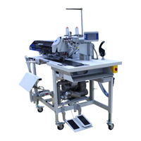
Category: Sewing Machine
|
Size: 49.85 MB
Table of Contents
Advertisement
DURKOPP ADLER 745-35-10 S Operating Instructions Manual (284 pages)
Brand: DURKOPP ADLER
|
Category: Sewing Machine
|
Size: 34.22 MB