DURKOPP ADLER 745-34 Speedpocket Service Instructions Manual
Sewing unit for runstitching of rectangular piped pockets
Hide thumbs
Also See for 745-34 Speedpocket:
- Manual (96 pages) ,
- Parts list (87 pages) ,
- User manual (84 pages)
Table of Contents
Advertisement
Postfach 17 03 51, D-33703 Bielefeld • Potsdamer Straße 190, D-33719 Bielefeld
Telefon +49 (0) 521 / 9 25-00 • Telefax +49 (0) 521 / 9 25 24 35 • www.duerkopp-adler.com
Ausgabe / Edition:
Änderungsindex
06/2007
Rev. index: 02.0
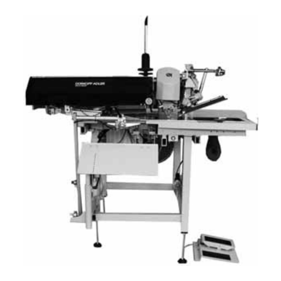
745 - 34 Speedpocket
Sewing unit for runstitching
of rectangular piped pockets
Operating Instructions
Installation Instructions
Instructions for programming DAC
Printed in Federal Republic of Germany
Service Instructions
Teile-Nr./Part.-No.:
0791 745171
1
2
3
4
Advertisement
Table of Contents

Related Manuals for DURKOPP ADLER 745-34 Speedpocket


Summary of Contents for DURKOPP ADLER 745-34 Speedpocket
-
Page 1: Operating Instructions
745 - 34 Speedpocket Sewing unit for runstitching of rectangular piped pockets Operating Instructions Installation Instructions Service Instructions Instructions for programming DAC Postfach 17 03 51, D-33703 Bielefeld • Potsdamer Straße 190, D-33719 Bielefeld Telefon +49 (0) 521 / 9 25-00 • Telefax +49 (0) 521 / 9 25 24 35 • www.duerkopp-adler.com Ausgabe / Edition: Änderungsindex Teile-Nr./Part.-No.:... - Page 2 All rights reserved. Property of Dürkopp Adler AG and copyrighted. Reproduction or publication of the content in any manner, even in extracts, without prior written permission of Dürkopp Adler AG, is prohibited. Dürkopp Adler AG - 2007 Copyright ©...
- Page 3 Foreword This instruction manual is intended to help the user to become familiar with the machine and take advantage of its application possibilities in accordance with the recommendations. The instruction manual contains important information on how to operate the machine securely, properly and economically. Observation of the instructions eliminates danger, reduces costs for repair and down-times, and increases the reliability and life of the machine.
-
Page 4: General Safety Instructions
General safety instructions The non-observance of the following safety instructions can cause bodily injuries or damages to the machine. 1. The machine must only be commissioned in full knowledge of the instruction book and operated by persons with appropriate training. 2. -
Page 5: Table Of Contents
Index Page: Part 3: Service Instructions 745-34 Speedpocket General notes..........Gauges . - Page 6 Index Page: Transport carriage Rear end position ..........3.1.1 Position of the limit switch in the slotted hole .
-
Page 7: General Notes
General notes The service instruction manual on hand describes the setting of the sewing unit 745-34 in an appropriate sequence. ATTENTION ! Some of the setting positions are interdependent. Therefore it is absolutely necessary to carry out the individual settings following the described order. -
Page 8: Gauges
Gauges The gauges listed below allow a precise setting and testing of the sewing unit. The locking peg 1 belongs to the standard accessories of the sewing unit. It serves to stake out the position A (looping stroke). The setting gauges marked with *) are available on inquiry. Position Setting gauge Order No. -
Page 9: Groove In The Arm Shaft Crank
Groove in the arm shaft crank The arm shaft crank 1 is provided with a groove 2 (5 mm). The machine head can be staked out with the locking peg through drill-hole 3. Now the machine head is in looping stroke position (position A). -
Page 10: Sewing Machine Head
Sewing machine head Raising the sewing machine head For maintenance work the machine head can be raised. For this purpose the transport carriage must be in its rear position. Caution: Danger of injury ! Switch the main switch off. Raise the machine head only with the main switch switched off. - Page 11 Raising the machine head – Remove the covering cap 1. For this purpose lift the covering cap at the front and at the back so that the arrest is released. Lift the covering cap carefully. – Swivel the folding station 3 out by 90°. –...
-
Page 12: Removing / Installing The Sewing Machine Head
Removing / Installing the sewing machine head For repair work or an easier change to another needle distance the machine head can be removed. For this purpose the transport carriage must be in its rear position. Caution: Danger of injury! Switch the main switch off and disconnect from the pneumatic net. - Page 13 Removing the machine head – Remove the covering cap 1. For this purpose lift the covering cap at the front and at the back so that the arrest is released. Lift the covering cap carefully. – Swivel the folding station 3 out by 90°. –...
-
Page 14: Crank Pin At The Arm Shaft
Crank pin at the arm shaft The distance between the eccentric crank pin 1 and the arm shaft 4 determines the needle bar stroke and thus the upper dead centre of the needle bars. ATTENTION ! The crank pin 1 has been precisely set by the manufacturer! After exchanging the thread lever the crank pin 1 has to be readjusted. - Page 15 Caution: Danger of injury ! Switch the main switch off. Adjust the crank pin only with the main switch switched off. – Remove the head cover 9 after loosening the fastening screws 8. – Swivel the thread tension plate 10 sideways after loosening the fastening screws 11.
- Page 16 – Detach the needle bar tie rod from the crank pin 1 after unscrewing its fastening screws (ATTENTION left-hand thread) and pull it off with the needle cage. – Turn the handwheel until the Allen screws 2 point downward. In this position the screws are accessible. –...
-
Page 17: Needle Bar Linkage
Needle bar linkage 2.4.1 Removing the needle bar linkage Caution: Danger of injury! Switch the main switch off. Remove the needle bar linkage only with the sewing unit switched off. – Unscrew the screws 1 and take off the head cover 2. –... - Page 18 – Loosen the counternut 12. – Loosen the adjusting screw 13 a bit. ATTENTION ! Do not loosen both adjusting screws 13. With the two adjusting screws 13 the correct height of the linkage frame has been set by the manufacturer. ATTENTION ! Avoid damage to the oil wick when taking off the needle bar.
-
Page 19: Removing A Needle Bar From The Linkage
2.4.2 Removing a needle bar from the linkage – Loosen the clamping screw 1. – Pull out the bearing bolt 2 – Pull off the support plate 3 from the needle bar linkage. – Unscrew the screws 8 and 10. –... -
Page 20: Disassembly Of The Needle Bar
2.4.3 Disassembly of a needle bar – Remove the linkage 16 and the needle bar as described under 2.4.1. – Screw off the screw 1 and unscrew the needle holder 2. – Unscrew the screw 15 and loosen the spring counter bearing 16. ATTENTION !The spring counter bearing is under spring pressure. -
Page 21: Installation Of The Needle Bars In The Needle Bar Linkage
2.4.5 Installation of the needle bars in the needle bar linkage – Insert the needle bar 7 in the linkage 10 from below. – Insert the needle bar in yoke 14 and clamping ring 13. The thin side of the clamping ring must point to the other needle bar and its indentation must point upwards. - Page 22 – Fasten the clamping ring 13 on the needle bar. Please observe that both clamping rings 13 with their round extensions are guided in clevis 17 fastened on the yoke. After tightening the fastening screw 15 the safety bolt 16 has to be tightened, too. –...
-
Page 23: Installation Of The Needle Bar Linkage
2.4.6 Installation of the needle bar linkage Caution: Danger of injury ! Switch the main switch off. Mount the needle bar linkage only with the sewing unit switched off. – Push the support plate 4 on the needle bar linkage 5. –... - Page 24 – Push the thread puller 11 on the pins 9 and 12 and tighten with screws 10 and 13. – Adjust the thread puller (see chapter 2.10).
-
Page 25: Height Of The Needle Bar Linkage
2.4.7 Height of the needle bar linkage 0,2 mm Caution: Danger of injury ! Switch the main switch off. Check and adjust the height of the needle bar linkage only with the sewing unit switched off. Standard checking If the two needle bars in the top dead centre are engaged, there must be a distance of 0.2 mm between the yoke 4 and the needle bar linkage 3. -
Page 26: Aligning The Needle Bar Linkage To The Throat Plate
2.4.8 Aligning the needle bar linkage to the throat plate Caution: Danger of injury ! Switch the main switch off. Check and adjust the alignment of the needle bar linkage only with the sewing unit switched off. Standard checking The needles should penetrate in the centre of the holes of throat plate 3. -
Page 27: Exchanging The Needle Holder
2.4.9 Exchanging the needle holder Caution: Danger of injury ! Switch the main switch off. Check and exchange the needle holder only with the sewing unit switched off. ATTENTION ! For changing a needle holder the needle bar in question must be in position “down”. -
Page 28: Hook
Hook 2.5.1 Hook shaft height Standard checking The distance between the throat plate support 4 and the flange surface 1 of the hook shaft must amount to 17.7 mm. The exact height of the hook shafts is set by means of gauge 3 (order number 0244 001001). -
Page 29: Adjusting The Gear Clearance Of The Hook Drive
2.5.2 Gear clearance of the hook drive Standard checking The gear clearance between worm and worm wheel should be as small as possible. The free movement must, however, remain guaranteed. The gear clearance has to be reset after every adjustment of the hook drive in axial direction (alteration of the needle distance). -
Page 30: Looping Stroke
2.5.3 Looping stroke Standard checking The looping stroke is the way of the needle bars from the bottom dead centre to the point where the hook tips 3 are at the level of the middle of needle 4. The looping stroke is 2 mm. It is set with the locking peg (order number 0211 000700). -
Page 31: Height Of The Needle Holders
2.5.4 Height of the needle holders 1,5 mm Standard checking In looping stroke position the distance between the top edge of the needle’s eye and the hook tip 2 must amount to 1.5 mm. The setting is done by means of the measuring bridge 3 (order number 0212 004942) and the measuring pin 4 (order number 0216 001070). - Page 32 Correction – Remove the throat plate. – Remove the needles from the needle holders. Hint For turning the needle holders one needle bar each has to be disconnected. – Move the needle bars by handwheel nearly up to the top dead centre.
-
Page 33: Distance Between Hook Tips And Needles
2.5.5 Distance between hook tips and needles Standard checking In looping stroke position the distance between the hook tips 6 and the needles 7 should amount to 0.1 mm. The set distance allows to work with needle sizes Nm 90 to Nm 110. When changing between these needle sizes a correction of the distance between the hook tips and the needles is not necessary. - Page 34 – Loosen screw 12. – Reset the needle protection 11 by turning the eccentric bolt 13. – Remove the needle from the needle holder. – Push the adjusting pin 5 into the needle holder as far as it will go. –...
-
Page 35: Needle Protection
2.5.6 Needle protection 0,1 mm Standard checking The needle protection 1 avoids that the needle 4 is deflected into the path of the hook tip 5. Before the hook tip 5 reaches the needle, the needle point must abut on the needle protection 1. It must not be possible to push the needle into the path of the hook tip 5. -
Page 36: Exchanging The Hook
2.5.7 Exchanging the hook Caution: Danger of injury ! Switch the main switch off. Exchange the hook only with the sewing unit switched off. – Remove the throat plate 6 after loosening the fastening screws. – Remove the bobbin case top part 1 with bobbin. –... -
Page 37: Bobbin Case Holding Wire
2.5.8 Bobbin case holding wire Function The bobbin case holding wire 6 holds the bobbin case top and bottom parts in a certain position against the rotary motion of the hook. The needle thread loop guided around the hook is pulled between the springy holding wire 6 and the edge 5 of the bobbin case top part. - Page 38 Correction – Loosen the clamping screw 3. – Adjust the holding wire 1. The holding wire must project from the plate 5 by 13 mm. – Tighten the clamping screw 3. – Loosen screw 6. – Adjust the height of plate 5. The holding wire 1 must abut in front of the edge 2 of the bobbin case top part 9.
-
Page 39: Center Knife
Center knife 2.6.1 Removing / Installing the driving motor Caution: Danger of injury ! Switch the main switch off Remove and install the driving motor only with the sewing unit switched off. Removing the driving motor – Unscrew the screws 6 at the driving motor and pull off cover 1. –... -
Page 40: Removing / Installing The Switching Cylinder
2.6.2 Removing / Installing the switching cylinder Caution: Danger of injury ! Switch the main switch off. Remove and mount the switching cylinder only with the sewing unit switched off. Removing the switching cylinder – Pull off the pneumatic hoses 3 and 4. –... -
Page 41: Adjusting The Knife
2.6.3 Adjusting the knife Caution: Danger of injury ! Switch the main switch off. Separate the sewing unit from the pneumatic net. Adjust the center knife only with the sewing unit switched off. Standard checking In the bottom dead centre the front edge 2 of center knife 3 must jut out approx. - Page 42 – Loosen screws 5 and 6. – Place the knife holder 4 with the center knife 3 to the left against the stationary knife in the throat plate. The center knife must abut in parallel position and with slight pressure. –...
-
Page 43: Thread Controller Spring
Thread controller spring Caution: Danger of injury! Switch the main switch off. Adjust the thread controller spring only with the sewing unit switched off. Standard checking The thread controller springs must keep the needle threads under tension until the needle points penetrate the fabric. If the needle threads are slack when the needles penetrate the fabric it may happen that the needles prick the threads when moving down. -
Page 44: Trimming And Clamping Device For The Needle Threads
Trimming and clamping device for the needle threads 2.8.1 Function Caution: Danger of injury! Switch the main switch off. Check knife and thread catcher only with the sewing unit switched off. Function – The cylinder 2 is switched on after the seam end and during the feed to the corner knives. -
Page 45: Exchanging Knife And Thread Catcher
2.8.2 Exchanging knife and thread catcher 0,5 mm Caution: Danger of injury ! Switch the main switch off. Exchange knife and thread catcher only with the sewing unit switched off. Standard After a certain service life the knife 5 loses its sharpness. The blunt knife has to be removed for resharpening. - Page 46 Mounting the complete thread catcher – Mount the complete thread catcher on the machine head. – Mount the complete thread catcher in such a way that the needle thread catcher 3 is centric between the needles. – Adjust the height of the thread catcher so that the dimension between sliding sheet and lower edge of the needle thread catcher is 27 +/- 1 mm.
-
Page 47: Trimming And Clamping Device For The Hook Threads
Trimming and clamping device for the hook threads Function – After the seam end and during the thread pulling process the hook threads are pulled through the thread grooves of the throat plate into the open hook thread scissors 2 and the hook thread clamp 1. –... - Page 48 Standard The top edge of the hook thread scissors 2 must be on the same level as the top side of the throat plate. A hook thread scissors in a too high position may damage the fabric. If the hook thread scissors is positioned too low, the hook threads are not cut off.
- Page 49 – Align the spring clamping sheets 3. The spring clamping sheets must abut on the throat plate panel flat and with slight spring pressure. Check the safety distance between the hook tips and the pneumatically opened thread clamps. For this purpose please proceed as follows: –...
-
Page 50: Thread Puller For The Needle Threads
2.10 Thread puller for the needle threads Caution: Danger of injury ! Switch the main switch off. Adjust the thread puller only with the sewing unit switched off. Standard checking The thread puller 1 pulls a certain needle thread quantity out of the opened thread tension. -
Page 51: Synchronizer
2.11 Synchronizer Caution: Danger of injury! Switch the main switch off. Adjust the synchronizer only with the sewing unit switched off. Standard checking After positioning the thread lever should be approx. 5 mm in front of the top dead centre. The distance between the synchronizer 2 and the cam segment 5 should amount to approx. -
Page 52: Oil Lubrication
2.12 Oil lubrication Caution: Danger of injury ! Oil can cause skin rashes. Avoid longer skin contact. After contact wash yourself thoroughly. ATTENTION ! The handling and disposal of mineral oils is subject to legal regulations. Deliver used oil to an authorized collecting station. Protect your environment. -
Page 53: Hook Lubrication
2.12.1 Hook lubrication Standard The necessary oil quantity has been adjusted by the manufacturer with the screws 7 and 8. It should be reduced or increased in special cases only. – Adjust the screws 7 and 8. – Screw the screws in: less oil –... - Page 54 Note:...
-
Page 55: Transport Carriage
Transport carriage Rear end position Standard checking The switch 1 determines the rear and by means of a definitely specified path also the front end position of the transport carriage. The switching screw 3 should be 12 mm above the fastening surface at the transport carriage. -
Page 57: Position Of The Limit Switch In The Slotted Hole
3.1.1 Position of the limit switch in the slotted hole Checking – Unscrew screws 7 and take off the covering cap 6. – Check the position of the limit switch 1 in the slotted hole 2. Correction – Loosen the upper counternut at the limit switch 1. –... -
Page 58: Changing The Toothed Belt
Changing the toothed belt Caution: Danger of injury ! Switch the main switch off. Change the toothed belt only with the sewing unit switched off. For an easier exchange the toothed belt 4 is divided. It is held together by the belt clamp 3. Removing the old toothed belt –... -
Page 59: Adjusting The Belt Tension
Adjusting the belt tension Caution: Danger of injury ! Switch the main switch off. Adjust the belt tension only with the sewing unit switched off. Correction – Push the transport carriage to the front. – Measure the distance between the toothed belt and the upper edge of the table top with a tape measure 1. -
Page 60: Feeding Clamps
Feeding clamps Measuring line for aligning the feeding clamps and the folder For an unhindered material feed and a perfect pocket opening the folding and cutting tools as well as the marking lamps must be aligned to the middle of the pocket opening. The middle between both needle holders is considered as the middle of the pocket opening. -
Page 61: Aligning The Feeding Clamps As To The Auxiliary Line
Aligning the feeding clamps as to the auxiliary line Caution: Danger of injury ! Switch the main switch off. Check the parallel position of the feeding clamps only with the sewing unit switched off. Standard checking The feeding clamps 5 must be in parallel position to the pick-up folder and to the auxiliary line 2. -
Page 62: Feeding Clamp Stroke
Feeding clamp stroke Caution: Danger of injury ! Switch the main switch off. Check and adjust the feeding clamp stroke only with the sewing unit switched off. Standard checking When the flap clamps 4 are closed, the raised feeding clamps 2 and 3 must pass the machine arm 1 without hitting it. -
Page 63: Distance Between The Feeding Clamps And The Folder Sole
Distance between the feeding clamps and the folder sole Standard checking Between the outer edges 1 of the folder sole and the inner edges 2 of the feeding clamps there must be a certain distance. When processing medium-weight clothing fabrics the distance should amount to approx. -
Page 64: Front End Position Of The Feeding Clamp
Front end position of the feeding clamp Caution: Danger of injury ! Switch the main switch off. Adjust the feeding clamp with utmost caution. – Move towards the reference point (switch 1). The feeding clamp runs to the front end position. –... -
Page 65: Knives For Corner Incision
Knives for corner incision Caution: Danger of injury ! Do not reach into the area of the corner knives. The corner knives shooting up can cause severe cuts. Carry out adjusting operations with utmost caution when the sewing unit is running. Presetting In order to be able to precisely adjust the position of the corner knives 1 all four corner knives are at first brought in a basic position. -
Page 66: Aligning The Corner Knife Station As To The Seams
Aligning the corner knife station as to the seams Caution: Danger of injury ! Switch the main switch off. Adjust the corner knife station only with the sewing unit switched off. Standard checking The corner incisions must be symmetrical to the seams. –... - Page 67 – Loosen the screws 3 slightly. – Shift the holder 2 correspondingly. – Tighten the screws 3. – Swing the corner knife station in again. – Correct the distance from the switch 6. Correction of the corner incision at the seam beginning –...
-
Page 68: Adjusting The Slant Of The Corner Incisions
Adjusting the slant of the corner incisions Caution: Danger of injury ! Switch the main switch off. Adjust the corner knives only with the sewing unit switched off. Standard checking The incisions of the corner knives should be as close to the seam as possible, but must not cut it. -
Page 69: Exchanging The Corner Knives
Exchanging the corner knives Caution: Danger of injury ! Switch the main switch off. Exchange the corner knife station only with the sewing unit switched off. Danger of cuts. Do not reach into the sharp edges of the corner knives. Blunt knives are to be exchanged against a set of knives included in the accessories. -
Page 70: Laser Markings
Laser markings Class 745-34 S is equipped with 3 standard laser modules for marking the positioning points. The laser .. (Nummer einfügen?) marks the front positioning point for the left or right workpiece, the laser .. marks the rear positioning point. The laser .. marks the middle of the pocket opening. -
Page 71: Aligning The Markings
Aligning the markings Caution: Danger of injury ! Laser light. Do not look into the light source. The markings 13 mark the seam beginning, the markings 14 the middle of the pocket opening and the markings 15 the seam end. The markings 1 and 3 must be aligned as to the cutting line 6 (middle of pocket opening). -
Page 72: Reflected Light Barriers For Flap Scanning
Reflected light barriers for flap scanning Swivel arm Caution: Danger of injury ! Switch the main switch off. Adjust the swivel arm of the reflected light barriers only with the sewing unit switched off. Standard checking The swivel arm 1 should stand in parallel position to the machine arm. When swivelled in front of the arm it must snap in safely. -
Page 73: Aligning The Light Barriers
Aligning the light barrier for flap See Programming Instructions chapter 4... -
Page 74: Aligning The Folding Station Plate As To The Measuring Line
Aligning the folding station plate as to the measuring line 79 mm Caution: Danger of injury ! Switch the main switch off. Adjust the folding station plate of the loading station only with the sewing unit switched off. Standard checking The distance between the middle of the needle and the inner side of the folding station plate 1 must amount to 79 mm. -
Page 75: Positioning The Sewing Machine Head As To The Table Top
Positioning the sewing machine head as to the table top Caution: Danger of injury ! Switch the main switch off. Adjust the sewing machine head only with the sewing unit switched off. Standard checking The non-varnished surface of the base plate 1 of the sewing machine head must be at the same level as the table top 2 over its whole length. -
Page 76: Folder
10. Folder 10.1 Proper fastening Caution: Danger of injury ! Switch the main switch off. Remove and mount the folder only with the sewing unit switched off. Standard The folder 3 has to be pushed upwards until it abuts on the clamping collar 1. -
Page 77: Aligning The Folder As To The Middle Of The Pocket Opening
10.2 Aligning the folder as to the middle of the pocket opening Caution: Danger of injury ! Switch the main switch off. Align the folder as to the middle of the pocket opening only with the main switch switched off. Standard checking If properly fitted, the folder can be aligned as to the middle of the pocket opening from the measuring line 1. -
Page 78: Lifting Motion Of The Folder
10.3 Lifting motion of the folder Caution: Danger of injury ! Switch the main switch off. Adjust the lifting motion of the folder only with the sewing unit switched off. Standard checking When the folder is lowered – Lower the folder 2 on the fabric sliding sheet 1. In this position there must be a clearance of 0.3 - 0.5 mm between the guide roller 3 and the lowest point of the guide groove 4. - Page 79 Caution: Danger of injury ! Switch the main switch off. Adjust the guide groove for the folder only with the sewing unit switched off. – Loosen the screw 8. – Shift the cam piece 6 in the slotted holes. – Tighten the screw 8.
-
Page 80: Position Of The Folder To The Needles
10.4 Position of the folder to the needles Caution: Danger of injury ! Switch the main switch off. Align the folder as to the needles and to the center knife only with the sewing unit switched off. Standard checking When the folder is properly fastened, the following conditions must be fulfilled: When the folder is lowered, the needles must stick in the needle holes of the folder sole 1 without hindrance (without being pushed out of the... -
Page 81: Guide Plates At The Folder
10.5 Guide plates at the folder Caution: Danger of injury! Switch the main switch off. Adjust the guide plates only with the sewing unit switched off. Standard checking When the folder is lowered, the edges 3 of the guide plates 2 must project beyond the needles by approx. -
Page 82: Stacker
Stacker The basic stacker settings mentioned hereafter have been made by the manufacturer in factory 6. They have to be corrected in exceptional cases only. Caution: Danger of injury ! Before carrying out any adjustment work switch off the main switch and separate the stacker from the compressed air supply. -
Page 83: Position And Closing Of The Pincers
11.3 Position and closing of the pincers Standard checking When the cylinder 3 extends, the disc 2 reaches the bushing 4 after ~42mm. This is the front position of the pincers 1 (from this position the pincers closes, when the cyclinder 3 is moving on, and clamps the material). -
Page 84: Cylinder Speed
11.4 Cylinder speed The speed can be set with the throttling valves at the cylinders 1 and 2. Adjust the end cushioning 7 at the cylinder 2 in such a way that the lever reaches the end position rapidly, but not abruptly. 11.5 Position of the rest plate The height of the bow 3 with rest table 4 can be adjusted so that workpieces of different length and bundles of different thickness can... -
Page 85: Swivelling The Stacker Aside
11.6 Swivelling the stacker aside For adjusting the corner knives the stacker can be swivelled aside. – Loosen the pawl 1. – Swivel the stacker aside. – Let the stacker catch in its position again after the adjusting operations. – With the screw 2 the stacker can be set close to the stand. - Page 86 Note:...