Table of Contents
Advertisement
Quick Links
Advertisement
Table of Contents
Troubleshooting

Related Manuals for Daikin REYQ-TA Series


Summary of Contents for Daikin REYQ-TA Series
- Page 1 SiUS371614E Service Manual REYQ72-456TAYDU REYQ72-456TATJU Heat Recovery 60 Hz...
- Page 2 SiUS371614E REYQ-TA Series Heat Recovery R-410A 60 Hz ED Reference For items below, please refer to Engineering Data. Item Model ED No. Page FXFQ-T EDUS391400-F14 FXFQ-P EDUS391000-F1 FXZQ-M EDUS391300-F9 FXUQ-P EDUS391437-F15 FXEQ-P EDUS391533-F16 FXDQ-M EDUS39-600-F2 VRV indoor unit FXMQ-PB EDUS391503-F4...
-
Page 3: Table Of Contents
SiUS371614E 1. Safety Cautions..................vii 1.1 Warnings and Cautions Regarding Safety of Workers........ vii 1.2 Warnings and Cautions Regarding Safety of Users........ix 2. Icons Used ....................xii Part 1 General Information .............. 1 1. Model Names of Indoor/Outdoor Units............2 1.1 Indoor Unit.................... - Page 4 SiUS371614E 2.2 Wireless Remote Controller ............... 47 3. MAIN/SUB Setting..................48 3.1 BRC1E73 ....................48 3.2 Wireless Remote Controller ............... 49 4. Centralized Control Group No. Setting............50 4.1 BRC1E73 ....................50 4.2 Wireless Remote Controller ............... 52 4.3 Group No. Setting Example................ 53 5.
- Page 5 SiUS371614E 9. Outline of Control (Indoor Unit) ..............89 9.1 Operation Flowchart ................... 89 9.2 Set Temperature and Control Temperature ..........91 9.3 Remote Controller Thermistor ..............93 9.4 Thermostat Control..................95 9.5 Drain Pump Control..................98 9.6 Control of Electronic Expansion Valve ............. 100 9.7 Freeze-up Prevention................
- Page 6 SiUS371614E 3.2 Indoor Unit PCB Abnormality ..............172 3.3 Drain Level Control System Abnormality..........173 3.4 Fan Motor Lock, Overload................ 175 3.5 Indoor Fan Motor Abnormality..............178 3.6 Overload/Overcurrent/Lock of Indoor Fan Motor........182 3.7 Blower Motor Not Running ............... 183 3.8 Indoor Fan Motor Status Abnormality............
- Page 7 SiUS371614E 3.48 Power Supply Voltage Imbalance ............242 3.49 Reactor Temperature Abnormality ............244 3.50 Inverter Radiation Fin Temperature Abnormality ........245 3.51 Field Setting after Replacing Outdoor Unit Main PCB Abnormality or Combination of PCB Abnormality............. 246 3.52 Refrigerant Shortage ................247 3.53 Reverse Phase, Open Phase..............
-
Page 8: Safety Cautions
Safety Cautions SiUS371614E 1. Safety Cautions Be sure to read the following safety cautions before conducting repair work. After the repair work is complete, be sure to conduct a test operation to ensure that the equipment operates normally, and explain the cautions for operating the product to the customer. Caution Items The caution items are classified into Warning and... - Page 9 SiUS371614E Safety Cautions Warning Do not turn the air conditioner on or off by plugging in or unplugging the power cable. Plugging or unplugging the power cable to operate the equipment may cause an electrical shock or fire. Be sure to wear a safety helmet, gloves, and a safety belt when working in a high place (more than 2 m (6.5 ft)).
-
Page 10: Warnings And Cautions Regarding Safety Of Users
Safety Cautions SiUS371614E Caution Be sure to check that the refrigerating cycle section has cooled down enough before conducting repair work. Working on the unit when the refrigerating cycle section is hot may cause burns. Conduct welding work in a well-ventilated place. Using a welder in an enclosed room may cause oxygen deficiency. - Page 11 SiUS371614E Safety Cautions Warning When wiring between the indoor and outdoor units, make sure that the terminal cover does not lift off or dismount because of the cable. If the cover is not mounted properly, the terminal connection section may cause an electrical shock, excessive heat generation or fire.
- Page 12 Safety Cautions SiUS371614E Caution Do not install the equipment in a place where there is a possibility of combustible gas leaks. If combustible gas leaks and remains around the unit, it may cause a fire. Check to see if parts and wires are mounted and connected properly, and if the connections at the soldered or crimped terminals are secure.
-
Page 13: Icons Used
SiUS371614E Icons Used 2. Icons Used The following icons are used to attract the attention of the reader to specific information. Icon Type of Description Information Warning A warning is used when there is danger of personal injury. Warning Caution A caution is used when there is danger that the reader, through incorrect manipulation, may damage equipment, lose data, get Caution... -
Page 14: Part 1 General Information
SiUS371614E Part 1 General Information 1. Model Names of Indoor/Outdoor Units............2 1.1 Indoor Unit....................2 1.2 DOAS Unit....................2 1.3 Outdoor Unit ....................2 1.4 Air Treatment Equipment ................4 1.5 Branch Selector Unit ..................4 2. External Appearance................... 5 2.1 Indoor Unit.................... -
Page 15: Model Names Of Indoor/Outdoor Units
SiUS371614E Model Names of Indoor/Outdoor Units 1. Model Names of Indoor/Outdoor Units Indoor Unit Capacity Range (ton) 1.25 Power Supply, Capacity Index Standard Ceiling Mounted Cassette FXFQ 07T — — — — — — (Round Flow with Sensing) Type Ceiling Mounted Cassette FXFQ —... - Page 16 Model Names of Indoor/Outdoor Units SiUS371614E 1.3.1 Combination of Outdoor Units (Heat Recovery 460 V) REYQ-TAYDU Model name REYQ72TAYDU REYQ96TAYDU REYQ120TAYDU REYQ144TAYDU REYQ168TAYDU Outdoor unit 1 REYQ72TAYDU REYQ96TAYDU REYQ120TAYDU REYQ144TAYDU REYQ168TAYDU Model name REYQ192TAYDU REYQ216TAYDU REYQ240TAYDU REYQ264TAYDU REYQ288TAYDU Outdoor unit 1 REYQ72TAYDU REYQ96TAYDU REYQ96TAYDU...
-
Page 17: Air Treatment Equipment
SiUS371614E Model Names of Indoor/Outdoor Units Air Treatment Equipment Outdoor Air Processing Unit Series Model Name Power Supply, Standard FXMQ 48MF 72MF 96MF Energy Recovery Ventilator (VAM series) Series Model Name Power Supply, Standard 300G 470G 600G 1200G : 1 phase, 208/230 V, 60 Hz U(VJU) : Standard Symbol Branch Selector Unit Single Branch Selector Unit for Heat Recovery... -
Page 18: External Appearance
External Appearance SiUS371614E 2. External Appearance Indoor Unit Ceiling mounted cassette (Round flow with sensing) type Ceiling mounted duct type FXFQ-T FXMQ-M Shown with BYCQ125B-W1 Ceiling mounted cassette (Round flow) type Ceiling suspended type FXFQ-P FXHQ-M Shown with BYCP125K-W1 4 way ceiling mounted cassette (2’×2’) type Wall mounted type FXZQ-M FXAQ-P... -
Page 19: Doas Unit
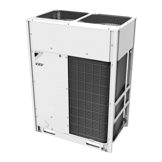
SiUS371614E External Appearance DOAS Unit DVSV05/10/12 Outdoor Unit Single Outdoor Unit REYQ72TAYDU REYQ96/120/144/168TAYDU REYQ72TATJU REYQ96/120/144/168TATJU Double Outdoor Unit REYQ192TAYDU REYQ216/240/264/288/312/336TAYDU REYQ192TATJU REYQ216/240/264/288/312/336TATJU General Information... -
Page 20: Air Treatment Equipment
External Appearance SiUS371614E Triple Outdoor Unit REYQ360/384/408/432/456TAYDU REYQ360/384/408/432/456TATJU Air Treatment Equipment Outdoor air processing unit Energy recovery ventilator (VAM series) FXMQ-MF VAM-G Branch Selector Unit Single branch selector unit Multi branch selector unit BS-Q54T BSQ-T General Information... -
Page 21: Combination Of Outdoor Units
SiUS371614E Combination of Outdoor Units 3. Combination of Outdoor Units System capacity Module Number of Outdoor Unit Multi Connection units Piping Kit 21.1 28.1 12.5 35.2 — 42.2 17.5 49.2 56.3 22.5 63.3 70.3 27.5 77.4 BHFP26P100U 84.4 32.5 91.4 98.5 37.5 105.5... -
Page 22: Capacity Range
Capacity Range SiUS371614E 4. Capacity Range Combination Ratio Total capacity index of the indoor units Combination ratio = Capacity index of the outdoor units Max. combination ratio Type of connected air treatment Types of connected indoor units equipments Min. Type combination When using FXMQ-MF... -
Page 23: Limitation Of Capacity Index For Heat Recovery
SiUS371614E Capacity Range Limitation of Capacity Index for Heat Recovery Single Branch Selector unit Model BSQ36TVJ BSQ60TVJ BSQ96TVJ Maximum number of connectable indoor units unit ≤ 36 36 < unit ≤ 60 60 < unit ≤ 96 Total capacity index of connectable indoor units Multi Branch Selector unit Model BS4Q54TVJ... -
Page 24: Part 2 Refrigerant Circuit
SiUS371614E Part 2 Refrigerant Circuit 1. Refrigerant Circuit ..................12 1.1 Outdoor Unit ....................12 1.2 Indoor Unit....................16 1.3 Outdoor-Air Processing Unit............... 18 1.4 Branch Selector Unit .................. 19 2. Functional Parts Layout ................25 2.1 REYQ72TAYDU ..................25 2.2 REYQ96/120TAYDU .................. 26 2.3 REYQ144/168TAYDU ................ -
Page 25: Refrigerant Circuit
SiUS371614E Refrigerant Circuit 1. Refrigerant Circuit Outdoor Unit 1.1.1 REYQ72TAYDU, REYQ72TATJU No. in Electric piping Name Major function symbol diagram Inverter compressor is operated on frequencies between 52 Hz to 210 Hz by using the Inverter compressor inverter. Compressor operation steps: Refer to page 66~ Because the system is an air heat exchange type, the fan is operated at 9-step rotation Inverter fan speed by using the inverter. - Page 26 Refrigerant Circuit SiUS371614E REYQ72TAYDU, REYQ72TATJU Refrigerant Circuit...
- Page 27 SiUS371614E Refrigerant Circuit 1.1.2 REYQ96-168TAYDU, REYQ96-168TATJU No. in Electric piping Name Major function symbol diagram Inverter compressor Inverter compressor is operated on frequencies between 52 Hz to 210 Hz by using the inverter. Compressor operation steps: Refer to page 66~ Inverter compressor Because the system is an air heat exchange type, the fan is operated at 9-step rotation Inverter fan...
- Page 28 Refrigerant Circuit SiUS371614E REYQ96-168TAYDU, REYQ96-168TATJU Refrigerant Circuit...
-
Page 29: Indoor Unit
SiUS371614E Refrigerant Circuit Indoor Unit Symbol No. in piping Except Name Function diagram FXMQ-PB, FXMQ-PB FXTQ-TA FXTQ-TA Used for gas superheated degree control while Electronic expansion in cooling or subcooled degree control while in valve heating. Suction air thermistor R1T (∗1) Used for thermostat control. - Page 30 Refrigerant Circuit SiUS371614E FXMQ-PB FXTQ-TA Gas piping connection port Indoor heat exchanger Liquid piping connection port Filter Filter C: 4D034245P C: 4D068194 Refrigerant Circuit...
-
Page 31: Outdoor-Air Processing Unit
SiUS371614E Refrigerant Circuit Outdoor-Air Processing Unit Gas pipe connection port Heat exchanger Filter Capillary tube Distributor Solenoid valve Liquid pipe connection port Check valve Filter Filter Electronic expansion valve C: 4D018650D No. in Electric piping Name Function symbol diagram Used to control the flow rate of refrigerant, and make the Electronic expansion valve SH control (∗1) while in cooling. -
Page 32: Branch Selector Unit
Refrigerant Circuit SiUS371614E Branch Selector Unit 1.4.1 Single Branch Selector Unit BSQ36-96TVJ Electric Name Function symbol Opens while in heating operation or all indoor units are in cooling. Electronic expansion valve (EVH) (Max : 760 pulse) Electronic expansion valve (EVL) Opens while in cooling. - Page 33 SiUS371614E Refrigerant Circuit 1.4.2 Multi Branch Selector Unit BS4Q54TVJ Electronic Expansion Valve (HP/LP gas) Electronic Expansion Valve Filter Gas pipe Double pipe heat (Subcooling) Electronic Expansion Valve (Suction) Filter connection port exchanger Liquid pipe connection port Electronic Expansion Valve (HP/LP gas) Electronic Expansion Valve Filter...
- Page 34 Refrigerant Circuit SiUS371614E BS6Q54TVJ Electronic Expansion Valve (HP/LP gas) Electronic Expansion Valve Filter Gas pipe Double pipe heat (Subcooling) Electronic Expansion Valve (Suction) Filter exchanger connection port Liquid pipe connection port Electronic Expansion Valve (HP/LP gas) Electronic Expansion Valve Filter Gas pipe Double pipe heat (Subcooling)
- Page 35 SiUS371614E Refrigerant Circuit BS8Q54TVJ Electronic Expansion Valve ( HP/LP gas ) Electronic Expansion Valve Filter Double pipe heat Gas pipe ( Subcooling ) Electronic Expansion Valve ( Suction ) Filter exchanger connection port Liquid pipe connection port Electronic Expansion Valve ( HP/LP gas ) Electronic Expansion Valve Filter...
- Page 36 Refrigerant Circuit SiUS371614E BS10Q54TVJ Electronic Expansion Valve (HP/LP gas) Electronic Expansion Valve Filter Double pipe heat Gas pipe (Subcooling) Electronic Expansion Valve (Suction) Filter exchanger connection port Liquid pipe connection port Electronic Expansion Valve (HP/LP gas) Electronic Expansion Valve Filter Double pipe heat Gas pipe (Subcooling)
- Page 37 SiUS371614E Refrigerant Circuit BS12Q54TVJ Electronic Expansion Valve (HP/LP gas) Electronic Expansion Valve Filter Double pipe heat (Subcooling) Gas pipe Electronic Expansion Valve (Suction) Filter exchanger connection port Liquid pipe connection port Electronic Electronic Expansion Valve (HP/LP gas) Expansion Valve Filter Double pipe heat Gas pipe (Subcooling)
-
Page 38: Functional Parts Layout
Functional Parts Layout SiUS371614E 2. Functional Parts Layout REYQ72TAYDU Top View Electronic expansion valve (Refrigerant cooling) (Y5E) Electronic expansion valve (Subcooling heat exchanger) Solenoid valve (Liquid shutoff) (Y2E) (Y3S) Four way valve (Heat exchanger lower) Solenoid valve (DS oil return) (Y5S) (Y1S) Four way valve... -
Page 39: Reyq96/120Taydu
SiUS371614E Functional Parts Layout REYQ96/120TAYDU Top View Electronic expansion valve Solenoid valve (Liquid shutoff) (Refrigerant cooling) (Y3S) (Y5E) Electronic expansion valve Solenoid valve (DS oil return 2) (Subcooling heat exchanger) (Y2S) (Y2E) Four way valve (Heat exchanger upper) Solenoid valve (DS oil return 1) (Y6S) (Y1S) Four way valve... -
Page 40: Reyq144/168Taydu
Functional Parts Layout SiUS371614E REYQ144/168TAYDU Top View Electronic expansion valve (Refrigerant cooling) Solenoid valve (Liquid shutoff) (Y5E) (Y3S) Electronic expansion valve (Subcooling heat exchanger) Solenoid valve (DS oil return 2) (Y2E) (Y2S) Four way valve Solenoid valve (DS oil return 1) (Heat exchanger upper) (Y1S) (Y6S) -
Page 41: Reyq72Tatju
SiUS371614E Functional Parts Layout REYQ72TATJU Top View Electronic expansion valve Solenoid valve (Liquid shutoff) (Refrigerant cooling) (Y3S) (Y5E) Solenoid valve (DS oil return) Electronic expansion valve (Y1S) (Subcooling heat exchanger) (Y2E) Thermistor (Suction) Four way valve (R10T) (Heat exchanger lower) (Y5S) Four way valve (Heat exchanger upper) -
Page 42: Reyq96/120Tatju
Functional Parts Layout SiUS371614E REYQ96/120TATJU Top View Solenoid valve (Liquid shutoff) Electronic expansion valve (Y3S) (Refrigerant cooling) (Y5E) Solenoid valve (DS oil return 2) Electronic expansion valve (Y2S) (Subcooling heat exchanger) (Y2E) Solenoid valve (DS oil return 1) Four way valve (Y1S) (Heat exchanger lower) (Y5S) -
Page 43: Reyq144/168Tatju
SiUS371614E Functional Parts Layout REYQ144/168TATJU Top View Electronic expansion valve (Refrigerant cooling) Solenoid valve (Liquid shutoff) (Y5E) (Y3S) Electronic expansion valve Solenoid valve (DS oil return 2) (Subcooling heat exchanger) (Y2S) (Y2E) Four way valve (Heat exchanger upper) Solenoid valve (DS oil return 1) (Y6S) (Y1S) Four way valve... -
Page 44: Refrigerant Flow For Each Operation Mode
Refrigerant Flow for Each Operation Mode SiUS371614E 3. Refrigerant Flow for Each Operation Mode REYQ72TAYDU, REYQ72TATJU 3.1.1 Cooling Operation High temperature, high pressure gas High temperature, high pressure liquid Low temperature, low pressure gas Low temperature, low pressure liquid Stop valve ( With service port φ5/16in. ( 7.9mm ) flare connection ) Check valve Check valve Liquid... - Page 45 SiUS371614E Refrigerant Flow for Each Operation Mode 3.1.2 Heating Operation High temperature, high pressure gas High temperature, high pressure liquid Low temperature, low pressure gas Low temperature, low pressure liquid Stop valve ( With service port φ5/16in. ( 7.9mm ) flare connection ) Check valve Check valve Liquid...
- Page 46 Refrigerant Flow for Each Operation Mode SiUS371614E 3.1.3 Simultaneous Cooling and Heating Operation High temperature, high pressure gas High temperature, high pressure liquid Low temperature, low pressure gas Low temperature, low pressure liquid Stop valve ( With service port φ5/16in. ( 7.9mm ) flare connection ) Check valve Check valve Liquid...
- Page 47 SiUS371614E Refrigerant Flow for Each Operation Mode 3.1.4 Cooling Oil Return Operation High temperature, high pressure gas High temperature, high pressure liquid Low temperature, low pressure gas Low temperature, low pressure liquid Stop valve ( With service port φ5/16in. ( 7.9mm ) flare connection ) Check valve Check valve Liquid...
- Page 48 Refrigerant Flow for Each Operation Mode SiUS371614E 3.1.5 Defrost Heating Oil Return Operation High temperature, high pressure gas High temperature, high pressure liquid Low temperature, low pressure gas Low temperature, low pressure liquid Stop valve ( With service port φ5/16in. ( 7.9mm ) flare connection ) Check valve Check valve Liquid...
- Page 49 SiUS371614E Refrigerant Flow for Each Operation Mode 3.1.6 Oil Return Operation at Simultaneous Cooling and Heating Operation High temperature, high pressure gas High temperature, high pressure liquid Low temperature, low pressure gas Low temperature, low pressure liquid Stop valve ( With service port φ5/16in. ( 7.9mm ) flare connection ) Check valve Check valve Liquid...
-
Page 50: Reyq96-168Taydu, Reyq96-168Tatju
Refrigerant Flow for Each Operation Mode SiUS371614E REYQ96-168TAYDU, REYQ96-168TATJU 3.2.1 Cooling Operation High temperature, high pressure gas High temperature, high pressure liquid Low temperature, low pressure gas Low temperature, low pressure liquid Stop valve ( With service port φ5/16in. ( 7.9mm ) flare connection ) Check valve Check valve Liquid... - Page 51 SiUS371614E Refrigerant Flow for Each Operation Mode 3.2.2 Heating Operation High temperature, high pressure gas High temperature, high pressure liquid Low temperature, low pressure gas Low temperature, low pressure liquid Stop valve ( With service port φ5/16in. ( 7.9mm ) flare connection ) Check valve Check valve Liquid...
- Page 52 Refrigerant Flow for Each Operation Mode SiUS371614E 3.2.3 Simultaneous Cooling and Heating Operation High temperature, high pressure gas High temperature, high pressure liquid Low temperature, low pressure gas Low temperature, low pressure liquid Stop valve ( With service port φ5/16in. ( 7.9mm ) flare connection ) Check valve Check valve Liquid...
- Page 53 SiUS371614E Refrigerant Flow for Each Operation Mode 3.2.4 Cooling Oil Return Operation High temperature, high pressure gas High temperature, high pressure liquid Low temperature, low pressure gas Low temperature, low pressure liquid Stop valve ( With service port φ5/16in. ( 7.9mm ) flare connection ) Check valve Check valve Liquid...
- Page 54 Refrigerant Flow for Each Operation Mode SiUS371614E 3.2.5 Defrost Heating Oil Return Operation High temperature, high pressure gas High temperature, high pressure liquid Low temperature, low pressure gas Low temperature, low pressure liquid Stop valve ( With service port φ5/16in. ( 7.9mm ) flare connection ) Check valve Check valve Liquid...
- Page 55 SiUS371614E Refrigerant Flow for Each Operation Mode 3.2.6 Oil Return Operation at Simultaneous Cooling and Heating Operation High temperature, high pressure gas High temperature, high pressure liquid Low temperature, low pressure gas Low temperature, low pressure liquid Stop valve ( With service port φ5/16in. ( 7.9mm ) flare connection ) Check valve Check valve Liquid...
-
Page 56: Part 3 Remote Controller
SiUS371614E Part 3 Remote Controller 1. Applicable Models ..................44 2. Names and Functions ................45 2.1 BRC1E73 ....................45 2.2 Wireless Remote Controller ............... 47 3. MAIN/SUB Setting..................48 3.1 BRC1E73 ....................48 3.2 Wireless Remote Controller ............... 49 4. Centralized Control Group No. Setting............50 4.1 BRC1E73 .................... -
Page 57: Applicable Models
SiUS371614E Applicable Models 1. Applicable Models Wired remote controller Wireless remote Series controller Navigation FXFQ-T – FXFQ-P FXZQ-M BRC7E830 FXUQ-P – FXEQ-P FXDQ-M FXMQ-PB BRC1E73 BRC4C82 FXMQ-M FXHQ-M BRC7E83 FXAQ-P BRC7E818 FXLQ-M – FXNQ-M FXTQ-TA BRC4C82 – – Remote Controller... -
Page 58: Names And Functions
Names and Functions SiUS371614E 2. Names and Functions BRC1E73 1. Operation mode selector button 11. LCD (with backlight) 4. Up button 5. Down button 6. Right button 7. Left button 9. Operation lamp 8. On/Off button 3. Menu/OK button 10. Cancel button 2. - Page 59 SiUS371614E Names and Functions 4. Up button Used to raise the setpoint. The item above the current selection will be highlighted. (The highlighted items will be scrolled continuously when the button is continuously pressed.) Used to change the selected item. 5.
-
Page 60: Wireless Remote Controller
Names and Functions SiUS371614E Wireless Remote Controller ON OFF DOWN ON OFF TEMP TIME DOWN RESERVE CANCEL TIMER TEST MODE SWING TEST TEST DISPLAY (SIGNAL TRANSMISSION) FAN SPEED CONTROL BUTTON Press this button to select the fan speed, HIGH or This lights up when a signal is being transmitted. -
Page 61: Main/Sub Setting
SiUS371614E MAIN/SUB Setting 3. MAIN/SUB Setting BRC1E73 Situation The MAIN/SUB setting is necessary when 1 indoor unit is controlled by 2 remote controllers. When you use 2 remote controllers (control panel and separate remote controller), set one to MAIN and the other to SUB. Setting The remote controllers are factory setting to MAIN, so you only have to change one remote controller from MAIN to SUB. -
Page 62: Wireless Remote Controller
MAIN/SUB Setting SiUS371614E Wireless Remote Controller Introduction To set the wireless remote controller, you have to set the address for: The receiver of the wireless remote controller The wireless remote controller. Setting the Address for the Receiver The address for the receiver of the wireless remote controller is factory setting to 1. To change this setting, proceed as follows: Set the wireless address switch (SS2) on the PCB according to the table below. -
Page 63: Centralized Control Group No. Setting
SiUS371614E Centralized Control Group No. Setting 4. Centralized Control Group No. Setting BRC1E73 In order to conduct the centralized remote control using the central remote controller and the unified ON/OFF controller, Group No. settings should be made by group using the operating remote controller. Make Group No. - Page 64 Centralized Control Group No. Setting SiUS371614E Note: For setting group No. of Energy recovery ventilator and wiring adaptor for other air conditioners, etc., refer to the instruction manual. NOTICE Enter the group No. and installation place of the indoor unit into the attached installation table. Be sure to keep the installation table with the operation manual for maintenance.
-
Page 65: Wireless Remote Controller
SiUS371614E Centralized Control Group No. Setting Wireless Remote Controller Group No. setting by wireless remote controller for centralized control 1. When in the normal mode, press INSPECTION/TEST button for 4 seconds or more to enter field setting mode. 2. Set mode No. 00 with MODE button. 3. -
Page 66: Group No. Setting Example
Centralized Control Group No. Setting SiUS371614E Group No. Setting Example Centralized Remote Controller Indoor/Outdoor Outdoor/Outdoor Indoor/Outdoor Outdoor/Outdoor F1 F2 F1 F2 F1 F2 F1 F2 F1 F2 F1 F2 P1 P2 F1 F2 P1 P2 F1 F2 P1 P2 F1 F2 P1 P2 Group Control by Remote Controller Main 1-00... -
Page 67: Service Mode
SiUS371614E Service Mode 5. Service Mode BRC1E73 Operating the remote controller allows service data to be acquired and various services to be set. Basic screen is displayed. Press the Cancel Press the button. Cancel Press and hold the Cancel button button for 4 seconds or more. - Page 68 Service Mode SiUS371614E Maintenance Menu Item 2 Remarks Indoor Unit Status 10.FLOAT FLOAT SWITCH ON/OFF 11.T1/T2 T1/T2 input from outside ON/OFF 12.Th1 Suction air thermistor 13.Th2 Heat exchanger liquid pipe thermistor 14.Th3 Heat exchanger gas pipe thermistor 15.Th4 Discharge air thermistor 16.Th5 —...
-
Page 69: Part 4 Functions And Control
SiUS371614E Part 4 Functions and Control 1. Operation Flowchart (Outdoor Unit) ............58 2. Stop Control ....................59 2.1 Stop due to Error ..................59 2.2 When System is in Stop Mode ..............59 2.3 Slave Unit Stops during Master Unit Operation.......... 59 3. - Page 70 SiUS371614E 9.6 Control of Electronic Expansion Valve ............. 100 9.7 Freeze-up Prevention................101 9.8 List of Swing Flap Operations ..............103 9.9 Hot Start Control (In Heating Only) ............104 9.10 Louver Control for Preventing Ceiling Dirt..........105 9.11 Heater Control (Except FXTQ-TA Models)..........106 9.12 Heater Control (FXTQ-TA Models)............
-
Page 71: Operation Flowchart (Outdoor Unit)
SiUS371614E Operation Flowchart (Outdoor Unit) 1. Operation Flowchart (Outdoor Unit) For detailed description of each function in the flow below, refer to the details on related function on the following pages. Stop control (1) Stop due to error (2) When system is in stop mode (3) Slave unit stops during master unit operation Special control Standby control... -
Page 72: Stop Control
Stop Control SiUS371614E 2. Stop Control Stop due to Error In order to protect compressors, if any of the abnormal state occurs, the system will stop with thermostat OFF and the error will be determined when the retry times reaches certain number. (Refer to "Error code and Descriptions"... -
Page 73: Standby Control
SiUS371614E Standby Control 3. Standby Control Restart Standby Used to forcedly stop the compressor for a period of 2 minutes, in order to prevent the frequent ON/OFF of the compressor and equalize the pressure within the refrigerant system. In addition, the outdoor fan carry out the residual operation for a while to suppress the acceleration of the pressure equalizing and melting of the refrigerant to the evaporator. -
Page 74: Startup Control
Startup Control SiUS371614E 4. Startup Control This control is used to equalize the pressure in the front and back of the compressor prior to the startup of the compressor, thus reducing startup loads. Furthermore, the inverter is turned ON to charge the capacitor. To avoid stresses to the compressor due to oil return or else after the startup, the following control is made and the position of the four way valve is also determined. -
Page 75: Startup Control In Heating
SiUS371614E Startup Control Startup Control in Heating Frequency step up 5 sec. interval Frequency (Hz) REYQ72TA REYQ96-168TA +3 Hz/5 sec. Inverter compressor 1 0 Hz (M1C) +3 Hz/5 sec. Inverter compressor 2 0 Hz (M2C) ∗ REYQ96-168TA only PI control Initial opening Electronic expansion... -
Page 76: Basic Control
Basic Control SiUS371614E 5. Basic Control Normal Operation Electric Symbol Function of Functional Part Normal Part Name REYQ REYQ72TA Normal Cooling Normal Heating Simultaneous 96-168TA Cooling / Heating PI control, High PI control, High PI control, High pressure protection, pressure protection, pressure protection, Low pressure Low pressure... -
Page 77: Compressor Pi Control
SiUS371614E Basic Control Compressor PI Control Carries out the compressor capacity PI control to maintain Te at constant during cooling operation and Tc at constant during heating operation to ensure stable unit performance. On multi-outdoor-unit systems, this control is made according to values of the first-priority unit, which is detected with the pressure sensor. - Page 78 Basic Control SiUS371614E Double Outdoor Units Standard type: REYQ192TA Standard type: REYQ216-336TA No. 1 No. 2 No. 3 No. 1 No. 3 No. 2 No. 4 No. 2 No. 1 No. 3 No. 2 No. 4 No. 1 No. 3 M1C M2C M1C M2C M1C M2C...
-
Page 79: Compressor Step Control
SiUS371614E Basic Control Compressor Step Control Compressor operations vary with the following steps according to information in Compressor PI Control on page 64. Furthermore, the operating priority of compressors is subject to information in Operation Priority and Rotation of Compressors on page 64. Single unit installation REYQ72TA Step No. - Page 80 Basic Control SiUS371614E REYQ96/120TA Step Step up (Hz) Step down (Hz) Step Step up (Hz) Step down (Hz) Step Step up (Hz) Step down (Hz) 52.0 52.0 120.8 56.4 64.4 154.4 164.4 154.4 164.4 52.8 52.8 122.4 56.6 66.0 156.6 166.6 156.6 166.6...
- Page 81 SiUS371614E Basic Control REYQ144/168TA Step Step up (Hz) Step down (Hz) Step Step up (Hz) Step down (Hz) Step Step up (Hz) Step down (Hz) 52.0 52.0 116.0 54.2 61.8 132.8 140.7 132.8 140.7 52.8 52.8 117.6 55.0 62.7 140.4 148.8 140.4 148.8...
-
Page 82: Electronic Expansion Valve Pi Control
Basic Control SiUS371614E Electronic Expansion Valve PI Control Main electronic expansion valve EVM control When the outdoor unit heat exchanging is performed via the condenser (Y5S or Y6S is set to OFF), this function is used to exert PI control on the electronic expansion valve (Y1E or Y3E) so that the condenser outlet subcooled degree (SC) will become constant. -
Page 83: Step Control Of Outdoor Fans
SiUS371614E Basic Control Step Control of Outdoor Fans Used to control the revolutions of outdoor fans in the steps listed in table below, according to condition changes. REYQ72TA REYQ96TA Standard (default) Standard (default) Step No. Heating, Heating, Cooling Step No. Cooling Simultaneous Simultaneous... - Page 84 Basic Control SiUS371614E REYQ120TA REYQ144/168TA Standard (default) Standard (default) Heating, Heating, Step No. Cooling Step No. Cooling Simultaneous Simultaneous 25(∗1) 26(∗1) 1072 1072 1005 1115 1005 1115 1050 1160 1050 1160 1096 1206 1096 1206 1040 1040 1135 1265 1110 51(∗2) 1021 1131...
-
Page 85: Heat Exchanger Control
SiUS371614E Basic Control Heat Exchanger Control While in heating or cool/heat simultaneous operation, ensure target condensing and evaporating temperature by changing over the air heat exchange of outdoor unit to the evaporator or the condenser in response to loads. Single system Outdoor unit Outdoor unit Lower side... -
Page 86: Protection Control
Protection Control SiUS371614E 6. Protection Control High Pressure Protection Control This high pressure protection control is used to prevent the activation of protection devices due to abnormal increase of high pressure and to protect compressors against the transient increase of high pressure. - Page 87 SiUS371614E Protection Control Heating Normal Operation < 3.17 MPa > 3.31 MPa (460 psi) (480 psi) Pc: High pressure sensor detection value for master > 3.39 MPa unit All units (492 psi) Compressor step: 1 9-step down After 10 > 3.31 MPa seconds (480 psi)
-
Page 88: Low Pressure Protection Control
Protection Control SiUS371614E Low Pressure Protection Control This low pressure protection control is used to protect compressors against the transient decrease of low pressure. Cooling Normal Operation < 0.25 MPa > 0.39 MPa (36.3 psi) (56.6 psi) Pe: Low pressure sensor detection value for master unit All compressors step.: 1... -
Page 89: Discharge Pipe Protection Control
SiUS371614E Protection Control Discharge Pipe Protection Control This discharge pipe protection control is used to protect the compressor internal temperature against an error or transient increase of discharge pipe temperature. HTdi > 115˚C Upper limit compressor step: (239˚F) max (Max. Step) HTdi: Value of inverter compressor Normal Operation discharge pipe temperature... -
Page 90: Compressor Body Protection Control
Protection Control SiUS371614E Compressor Body Protection Control This compressor body protection control is used to protect the compressor internal temperature against an error or transient increase of compressor body temperature. Contents The following control is performed for each compressor of single unit as well as multi units. Inverter compressor (only for type JT15JBVDKYR) Normal operation Compressor body... -
Page 91: Inverter Protection Control
SiUS371614E Protection Control Inverter Protection Control Inverter current protection control and radiation fin temperature control are performed to prevent tripping due to an error, or transient inverter overcurrent, and fin temperature increase. In the case of multi-outdoor-unit system, each inverter compressor performs these controls in the following sequence. - Page 92 Protection Control SiUS371614E Radiation fin temperature control Perform the following control of integrated as well as multi units for each inverter compressor. Normal operation Reduce compressor capacity When occurring 4 times within 60 Fin temperature standby minutes, the error code L4 is output. REYQ72TAYDU REYQ96-120TAYDU REYQ144-168TAYDU...
-
Page 93: Special Control
SiUS371614E Special Control 7. Special Control Pump Down Residual Operation Pc : High pressure sensor detection value Pe : Low pressure sensor detection value Ta : Outdoor air temperature Te : Low pressure equivalent saturation temperature HTdi : Value of inverter compressor discharge pipe temperature (Tdi) compensated with outdoor air temperature If the liquid refrigerant stays in the evaporator at the startup of a compressor, this liquid refrigerant enters the compressor, thus resulting in diluted oil in the compressor and then degraded lubrication performance. -
Page 94: Oil Return Operation
Special Control SiUS371614E Oil Return Operation In order to prevent the compressor from running out of oil, the oil return operation is conducted to recover oil that has flowed out from the compressor to the system side. Tc : High pressure equivalent saturation temperature Te : Low pressure equivalent saturation temperature TsA: Suction pipe temperature detected by thermistor R3T 7.2.1 Oil Return Operation in Cooling Operation... - Page 95 SiUS371614E Special Control 7.2.2 Oil Return Operation in Heating Operation Starting conditions Electric Symbol Part Name Oil return operation REYQ72TA REYQ96-168TA Inverter compressor 1 +1 to +6 steps from frequency to frequency when oil return is IN at a constant level Inverter compressor 2 —...
-
Page 96: Defrost Operation
Special Control SiUS371614E Defrost Operation To defrost the outdoor heat exchanger while in Evaporator, the defrost operation is conducted to recover the heating capacity. Tb: Heat exchanger deicer temperature Electric Symbol Part Name Defrost operation REYQ72TA REYQ96-168TA REYQ72TA: 282 Hz Inverter compressor 1 REYQ96-168TA: 252 Hz + 252 Hz Inverter compressor 2... -
Page 97: Cooling/Heating Mode Switching
SiUS371614E Special Control Cooling/Heating Mode Switching [While in cooling / heating mixed mode, single-room cooling → heating] First, the electronic expansion valve of the indoor unit in cooling operation will close, and the Y2E and Y3E electronic expansion valves of the branch selector unit will all close once. Next, the Y2E electronic expansion valve will open little by little to perform pressure equalization. - Page 98 Special Control SiUS371614E [While in cooling/heating mixed mode, single-room heating → cooling] First, the electronic expansion valve of the indoor unit in heating operation will close, and the Y2E and Y3E electronic expansion valves of the branch selector unit will all close once. Next, the Y3E electronic expansion valve will open little by little to perform pressure equalization.
- Page 99 SiUS371614E Special Control [While in all-room cooling operation → All-room cooling/heating simultaneous operation] Dual pressure gas pipe (1) All the indoor units in cooling operation · Using the dual pressure gas pipe as a suction Suction gas pipe gas pipe. Liquid pipe (2) Pump-down residual operation...
- Page 100 Special Control SiUS371614E [While in all-room heating operation or cooling/heating simultaneous operation → All-room cooling] Dual pressure gas pipe (1) In heating operation or cooling and heating simultaneous operation Suction gas pipe · Using the dual pressure gas pipe as a suction gas pipe.
-
Page 101: Other Control
SiUS371614E Other Control 8. Other Control Backup Operation If any of the compressors goes wrong, disable the relevant compressor or the relevant outdoor unit from operating, and then conduct emergency operation only with operational compressors or outdoor units. "Emergency operation with remote controller reset" and "Emergency operation with outdoor unit PCB setting"... -
Page 102: Outline Of Control (Indoor Unit)
Outline of Control (Indoor Unit) SiUS371614E 9. Outline of Control (Indoor Unit) Operation Flowchart Cooling Operation Start (Option) Turn ON Aux. electric : OFF ∗16 power supply heater Humidifier : OFF Initialize electronic expansion valve Swing flap Detect louver lock prevention condition? The previous settings of airflow LED in remote... - Page 103 SiUS371614E Outline of Control (Indoor Unit) Program dry operation Heating Operation (option) Program ∗7 dry display Drain : OFF pump kit ∗8 Thermostat status : Operating in L mode after it stops for 6 min. Operating in L mode Swing flap? Electronic 20E : expansion valve...
-
Page 104: Set Temperature And Control Temperature
Outline of Control (Indoor Unit) SiUS371614E Set Temperature and Control Temperature 9.2.1 Without Optional Infrared Presence/Floor Sensor The relationship between remote controller set temperature and control target temperature is described below. • When the suction air thermistor is used for controlling (Default), the control target temperature is determined as follows to prevent insufficient heating in heating operation. - Page 105 SiUS371614E Outline of Control (Indoor Unit) 9.2.2 With Optional Infrared Presence/Floor Sensor The relationship between remote controller set temperature and control target temperature is described below. The temperature difference for cooling ⇔ heating mode switching is 5°C (9°F). • • When using the floor temperature as the control target, the remote controller set temperature is equal to the actual control target temperature in heating operation.
-
Page 106: Remote Controller Thermistor
Outline of Control (Indoor Unit) SiUS371614E Remote Controller Thermistor Temperature is controlled by both the remote controller thermistor and suction air thermistor for the indoor unit. (This is however limited to when the field setting for the remote controller thermistor is set to Use.) Note: When outdoor air is introduced to the air-conditioner with mixed into indoor air, the room... - Page 107 SiUS371614E Outline of Control (Indoor Unit) Heating When heating, the hot air rises to the top of the room, resulting in the temperature being lower near the floor where the occupants are. When controlling by suction air thermistor only, the indoor unit may therefore be turned off by the thermostat before the lower part of the room reaches the set temperature.
-
Page 108: Thermostat Control
Outline of Control (Indoor Unit) SiUS371614E Thermostat Control 9.4.1 Without Optional Infrared Presence/Floor Sensor Whether the thermostat is turned on or off is determined by the difference between the remote controller set temperature and the actual detected room temperature (∗1). Normal operation ·... - Page 109 SiUS371614E Outline of Control (Indoor Unit) 9.4.2 With Optional Infrared Presence/Floor Sensor Whether the thermostat is turned on or off is determined by the difference between the remote controller set temperature and the detected temperature around people. Normal operation · Cooling operation ∆T ≤...
- Page 110 Outline of Control (Indoor Unit) SiUS371614E 9.4.3 Thermostat Control with Operation Mode Set to AUTO When the operation mode is set to AUTO on the remote controller, the system will conduct the temperature control shown below. Furthermore, setting changes of the differential value (D) can be made referring to page 114 and later (Field Setting from Remote Controller).
-
Page 111: Drain Pump Control
SiUS371614E Outline of Control (Indoor Unit) Drain Pump Control 9.5.1 Normal Operation Float switch Thermostat (running) Error display Drain pump 5 min. • The float switch is ON in normal operation. • When cooling operation starts (thermostat ON), the drain pump turns ON simultaneously. •... - Page 112 Outline of Control (Indoor Unit) SiUS371614E 9.5.3 If the Float Switch is OFF with the Thermostat OFF in Cooling Operation Float switch Thermostat (running) Error display Drain pump 5 min. 5 sec. • When the float switch turns OFF, the drain pump turns ON simultaneously. •...
-
Page 113: Control Of Electronic Expansion Valve
SiUS371614E Outline of Control (Indoor Unit) Control of Electronic Expansion Valve Electronic expansion valves in indoor units have the functions of conducting superheated degree control in cooling operation and subcooling degree control in heating operation. However, if the indoor units receive any control command such as a protection control command or a special control command from the outdoor unit, the units will give a priority to the control command. -
Page 114: Freeze-Up Prevention
Outline of Control (Indoor Unit) SiUS371614E Freeze-up Prevention Freeze-up Prevention by Off Cycle (Indoor Unit Individual Control) When the temperature detected by the liquid pipe temperature thermistor of the indoor heat exchanger drops too low, the unit enters freeze-up prevention control in accordance with the following conditions, and is also set in accordance with the conditions given below. - Page 115 SiUS371614E Outline of Control (Indoor Unit) Note: When the indoor unit is FXFQ, FXZQ or FXUQ, if the air outlet is set as dual-directional or tri- directional, the starting conditions will be changed as follows. Liquid pipe temperature ≤ 1°C (33.8°F) (for total of 15 minutes) Liquid pipe temperature ≤...
-
Page 116: List Of Swing Flap Operations
Outline of Control (Indoor Unit) SiUS371614E List of Swing Flap Operations Swing flaps operate as shown in table below. Flap FXFQ FXEQ FXHQ FXAQ Swing Horizontal Horizontal Horizontal Horizontal Hot start from defrost operation Airflow direction set Horizontal Horizontal Horizontal Horizontal Swing Horizontal... -
Page 117: Hot Start Control (In Heating Only)
SiUS371614E Outline of Control (Indoor Unit) Hot Start Control (In Heating Only) At startup with thermostat ON or after the completion of defrosting in heating operation, the indoor fan is controlled to prevent cold air from blasting out and ensure startup capacity. TH2: Temperature detected with the gas thermistor Tc : High pressure equivalent saturated temperature Starting condition... -
Page 118: Louver Control For Preventing Ceiling Dirt
Outline of Control (Indoor Unit) SiUS371614E 9.10 Louver Control for Preventing Ceiling Dirt We have added a control feature that allows you to select the range of in which air direction can be adjusted in order to prevent the ceiling surrounding the air discharge outlet of ceiling mounted cassette type units from being soiled. -
Page 119: Heater Control (Except Fxtq-Ta Models)
SiUS371614E Outline of Control (Indoor Unit) 9.11 Heater Control (Except FXTQ-TA Models) Note: Optional PCB KRP1B ... is required. The heater control is conducted in the following manner. Normal control While in heating, the heater control (ON/ Set temperature OFF) is conducted as shown on the right. 2˚C 2˚C (3.6˚F) -
Page 120: Heater Control (Fxtq-Ta Models)
Outline of Control (Indoor Unit) SiUS371614E 9.12 Heater Control (FXTQ-TA Models) Note: Optional heater kit HKS... is required. For FXTQ models, heater ON/OFF output from wiring adaptor interlocks with the operation of heater kit HKS….(When the heater 1 turns ON/OFF, heater output of wiring adaptor turns ON/OFF.) Fan residual operation also interlocks with the fan residual operation of heater kit HKS…. - Page 121 SiUS371614E Outline of Control (Indoor Unit) Condition A • No fan motor system error • High pressure condition: ON (∗1) • Liquid pipe temperature condition: ON (∗2) • Heater ON permission (Defrost/oil Return): 0 (∗4) & & • Not during defrost/oil return •...
- Page 122 Outline of Control (Indoor Unit) SiUS371614E 9.12.2 Heat Pump Lockout Control For heating operation, users can select to use electric heater. For this, signals are sent using ABC terminal of outdoor unit PCB. When the hot-water heating signal is received from the outdoor unit PCB, heating operation is performed only with the electric heater as manual backup operation.
-
Page 123: Step Thermostat Processing (Fxtq-Ta Models)
SiUS371614E Outline of Control (Indoor Unit) 9.13 3 Step Thermostat Processing (FXTQ-TA Models) Outline The thermostat ON/OFF for the indoor unit is controlled in accordance with [Thermostat Step 1]. The heater ON/OFF operation during heating is controlled as follows. Thermostat step 2, 3: Auxiliary electric heater control Thermostat step 1, 2: Heat pump lockout control For more details of the heater, refer to Heater Control (FXTQ-TA Models) on page 107. -
Page 124: Fan Control (Heater Residual) (Fxtq-Ta Models)
Outline of Control (Indoor Unit) SiUS371614E 9.14 Fan Control (Heater Residual) (FXTQ-TA Models) Outline If the indoor heater turned OFF from ON during heating operation, the fan will keep operating for further period of time in order to cool the heater. Detail Residual ON •... - Page 125 SiUS371614E Outline of Control (Indoor Unit) 9.15.3 Economizer When indoor and outdoor air temperatures are reversed, the compressor is stopped to let in the outdoor air to save energy. This operation is called economizer operation, and the equipment to detect indoor and outdoor air temperatures and open and close the damper to perform this operation is called an economizer.
-
Page 126: Part 5 Field Settings
SiUS371614E Part 5 Field Settings 1. Field Setting from Remote Controller............114 1.1 Wired Remote Controller................114 1.2 Wireless Remote Controller ..............116 1.3 Simplified Remote Controller..............117 1.4 Setting Contents and Code No. for Indoor Units ........118 2. Field Setting from Outdoor Unit............... 136 2.1 Accessing the BS Buttons on the Logic Board......... -
Page 127: Field Setting From Remote Controller
SiUS371614E Field Setting from Remote Controller 1. Field Setting from Remote Controller Individual function of indoor unit can be changed from the remote controller. At the time of installation or after service inspection / repair, make the field setting in accordance with the following description. Wrong setting may cause error. - Page 128 Field Setting from Remote Controller SiUS371614E Press Menu/OK button. Setting confirmation screen is displayed. <Setting confirmation screen> Select Yes and press Menu/OK button. Setting details are determined and field settings screen returns. In the case of multiple setting changes, repeat “ ”...
-
Page 129: Wireless Remote Controller
SiUS371614E Field Setting from Remote Controller Wireless Remote Controller UP button Mode No. Field setting mode DOWN button RESERVE button First code No. MODE button Second code No. INSPECTION/TEST button To set the field settings, you have to change: Mode No. First code No. -
Page 130: Simplified Remote Controller
Field Setting from Remote Controller SiUS371614E Simplified Remote Controller Mode No. First code Unit No. Second code No. (2)(8) (7) (4) (5) (6) 1. Remove the upper part of remote controller. 2. When in the normal mode, press the BS6 button (2) (field setting) to enter the field setting mode. 3. -
Page 131: Setting Contents And Code No. For Indoor Units
SiUS371614E Field Setting from Remote Controller Setting Contents and Code No. for Indoor Units : Factory setting Mode First Second Code No. Code Setting Contents (∗2) Approx. Approx. Ultra long life 10,000 5,000 Filter sign setting filter hrs. hrs. (Setting for display time to clean air filter) Approx. - Page 132 Field Setting from Remote Controller SiUS371614E Mode First Second Code No. Code Setting Contents (∗2) Setting of airflow rate Standard High ceiling 1 High ceiling 2 — Airflow direction setting F (4 directions) T (3 directions) — (Set when a blocking pad kit has been installed.) (2 directions) All direction Swing pattern settings...
- Page 133 SiUS371614E Field Setting from Remote Controller 1.4.1 Applicable Range of Field setting Ceiling mounted 4-way blow One way Slim Ceiling Ceiling Wall Floor Concealed cassette type ceiling blow ceiling mounted suspended mounted standing floor handling suspended cassette mounted duct type type type type...
- Page 134 Field Setting from Remote Controller SiUS371614E 1.4.2 Detailed Explanation of Setting Modes Filter Sign Setting If switching the filter sign ON time, set as given in the table below. First Code Second Standard Long Life Ultra Long Life Mode No. Contents Code No.
- Page 135 SiUS371614E Field Setting from Remote Controller (˚F) (˚C) 96.8 93.2 In cooling 89.6 Suction air Remote controller Suction air thermistor thermistor thermistor Suction air Suction air Remote controller 82.4 thermistor thermistor thermistor 78.8 75.2 71.6 (˚C) 62.6 66.2 69.8 73.4 80.6 84.2 87.8 91.4 98.6 (˚F)
- Page 136 Field Setting from Remote Controller SiUS371614E Filter Cleaning Sign Whether or not to display "Filter Cleaning" after operation of certain duration can be selected. Mode No. First Code No. Second Code No. Contents Displayed 10 (20) Not displayed ∗ Filter cleaning sign is not displayed when an Auto-clean Panel is connected. Time for Absence Area Detection (For units with an infrared presence/floor sensor only) By selecting the energy-saving operation mode in the absence, the target temperature is shifted to the energy-...
- Page 137 SiUS371614E Field Setting from Remote Controller Auxiliary Electric Heater ON/OFF Temperature Thermostat Set temperature Thermostat Toff + S (∗1) Ton + S (∗1) Note: ∗1. S value varies automatically based on the room temperature trend. FXFQ-T, FXMQ-PB Second Code No. Mode No.
- Page 138 Field Setting from Remote Controller SiUS371614E Setting the Airflow Rate when Heating The fan revolution is changed to maintain the sufficient distance for warm air to reach during the heating operation. The setting should be changed depending on the installation condition of the unit. Second Code No.
- Page 139 SiUS371614E Field Setting from Remote Controller Setting the Rate of Human Detection (For units with the infrared presence/floor sensor only) Set the sensitivity of the infrared presence sensor. • The infrared presence sensor can be disabled by selecting the Second code No. 04. (Note) When the infrared presence sensor is disabled, the remote controller menu does not display some functions such as the automatic draft reduction, energy-saving operation in absence and halt in absence.
- Page 140 Field Setting from Remote Controller SiUS371614E Compensating the Floor Temperature (For units with the infrared presence/floor sensor only) Offset the detected value of the infrared floor sensor with a certain temperature. This setting should be used to have the actual floor temperature detected when, for example, the unit is installed close to a wall. Mode No.
- Page 141 SiUS371614E Field Setting from Remote Controller Thermostat Switching Differential value during thermostat ON/OFF control can be changed. Mode No. First Code No. Second Code No. Contents 1°C (1.8°F) 12(22) 0.5°C (0.9°F) Airflow Setting when Heating Thermostat is OFF This setting is used to set airflow when heating thermostat is OFF. ∗...
- Page 142 Field Setting from Remote Controller SiUS371614E Setting of Airflow Rate Make the following setting according to the ceiling height. The second code No. is set to 01 at the factory. FXHQ, FXAQ Mode No. First Code No. Second Code No. Contents Standard 13 (23)
- Page 143 SiUS371614E Field Setting from Remote Controller Operation of Downward Flow Flap (for FXEQ model) When only the front-flow is used, sets yes/no of the swing flap operation of down-flow Model No. First Code No. Second Code No. Contents Equipped 13 (23) Not equipped Setting of Airflow Direction Adjustment Range Make the following airflow direction setting according to the respective purpose.
- Page 144 Field Setting from Remote Controller SiUS371614E Optional Kit Setting (UV lamp + Humidifier + Economizer) (for FXTQ-TA model) Contents Economizer setting for Mode No. First Code No. Second Code No. UV lamp + humidifier fan Mech standby duration speed (minutes) Refer to controller High Refer to controller...
- Page 145 Contents Not equipped 15 (25) Individual operation of ventilation Display of Contact Center (For BRC1E73 only) You can turn OFF the display of "DAIKIN Contact Center" as "Contact for Service Display." Mode No. First Code No. Second Code No. Contents...
- Page 146 Field Setting from Remote Controller SiUS371614E Setting "Restricted / Permitted" of Airflow Block (For units with the infrared presence/floor sensor only) Due to possibility of dew condensation, the airflow block function cannot be enabled when closure material kit, fresh air intake kit, natural / separately installed evaporation humidifier, or branch air duct is equipped. This setting will prevent the airflow block is advertently set to ON.
- Page 147 SiUS371614E Field Setting from Remote Controller 1.4.3 Outdoor-Air Processing Unit - Field Setting (Remote Controller) : Factory setting First Second Code No. Mode Setting Contents Code Filter contamination 2500 hr 1250 hr — — — — — — — — —...
- Page 148 Field Setting from Remote Controller SiUS371614E How to Select Operation Mode Whether operation by remote controller will be possible or not for turning ON/OFF, controlling temperature or setting operation mode is selected and decided by the operation mode given on the right edge of the table below. Example ON by remote OFF by remote...
-
Page 149: Field Setting From Outdoor Unit
SiUS371614E Field Setting from Outdoor Unit 2. Field Setting from Outdoor Unit To continue the configuration of the VRV IV heat recovery system, it is required to give some input to the logic board of the unit. This chapter will describe how manual input is possible by operating the BS buttons/DIP switches on the logic board and reading the feedback from the 7 segment displays. -
Page 150: Operating The Bs Buttons And Dip Switches On The Logic Board
Field Setting from Outdoor Unit SiUS371614E Operating the BS Buttons and DIP Switches on the Logic Board Operating the BS buttons By operating the BS buttons it is possible to: • Perform special actions (testrun, etc). • Perform field settings (demand operation, low noise, etc). Below procedure explains how to operate the BS buttons to reach the required mode in the menu, select the correct setting and modify the value of the setting. - Page 151 SiUS371614E Field Setting from Outdoor Unit Accessing modes BS1 is used to change the mode you want to access. • Access mode 1 Press BS1 once. Segment indication changes to: • Access mode 2 Press BS1 for at least 5 seconds. Segment indication changes to: INFORMATION If you get confused in the middle of the process, press BS1.
-
Page 152: Connecting Of The Optional Pc Configurator Cable To The Outdoor Unit
Field Setting from Outdoor Unit SiUS371614E Example: Checking the content of parameter [2-18] (to define the high static pressure setting of the outdoor unit's fan). Mode: 2 Setting: 18 • Make sure the segment indication is as during normal operation (default situation when shipped from factory). •... -
Page 153: Monitoring Function And Field Settings
SiUS371614E Field Setting from Outdoor Unit Monitoring Function and Field Settings The operation of the outdoor unit can further be defined by changing some field settings. Next to making field settings it is also possible to confirm the current operation parameters of the unit. The setting can also be performed via the PC configuration software. - Page 154 Field Setting from Outdoor Unit SiUS371614E [1-5]: shows the current Te target parameter position. [1-6]: shows the current Tc target parameter position. [1-10]: shows the total number of connected indoor units. It can be convenient to check if the total number of indoor units which are installed match the total number of indoor units which are recognized by the system.
- Page 155 SiUS371614E Field Setting from Outdoor Unit [2-9]: Tc target temperature during heating operation Value Tc target [2-9] 0 (default) Auto 41°C (105.8°F) 42°C (107.6°F) 43°C (109.4°F) 46°C (114.8°F) [2-12]: Enable the night-time low noise function and/or power consumption limitation via external control adaptor (DTA104A61/62) If the system needs to be running under night-time low noise operation or under power consumption limitation conditions when an external signal is sent to the unit, this setting should be changed.
- Page 156 Field Setting from Outdoor Unit SiUS371614E [2-21]: Refrigerant recovery/vacuuming mode In order to achieve a free pathway to reclaim refrigerant out of the system or to remove residual substances or to vacuum the system it is necessary to apply a setting which will open required valves in the refrigerant circuit so the reclaim of refrigerant or vacuuming process can be done properly.
- Page 157 SiUS371614E Field Setting from Outdoor Unit [2-30]: Power consumption limitation level (step 1) via the external control adaptor (DTA104A61/62) If the system needs to be running under power consumption limitation conditions when an external signal is sent to the unit, this setting defines the level power consumption limitation that will be applied for step 1.
- Page 158 Field Setting from Outdoor Unit SiUS371614E [2-34]: Indoor fan tap setting Indoor fan speed limitation related to connection capacity and outdoor air temperature for energy saving. Value Indoor fan tap setting [2-34] Fan speed is limited to L tap when indoor units 0 (default) capacity ≥...
- Page 159 SiUS371614E Field Setting from Outdoor Unit [2-37]: Heat pump lockout 2 Heat pump is locked out when this setting and an external input to ABC terminal are made. Automatic lockout When this setting is made, the auto-backup function will automatically be activated. This will allow the auxiliary or secondary heat source to be automatically energized in the event of a system failure related to outdoor units.
- Page 160 Field Setting from Outdoor Unit SiUS371614E [2-49]: Height difference setting Default value: 0. In case the outdoor unit is installed in the highest position (indoor units are installed on a lower position than outdoor units) and the height difference between the lowest indoor unit and the outdoor unit exceeds 50 m (164 ft), the setting [2-49] has to be changed to 1.
- Page 161 SiUS371614E Field Setting from Outdoor Unit [2-81]: Cooling comfort setting Value Cooling comfort setting [2-81] 1 (default) Mild Quick Powerful This setting is used in conjunction with setting [2-8] and [2-47]. [2-82]: Heating comfort setting Value Heating comfort setting [2-82] 1 (default) Mild Quick...
-
Page 162: Cool / Heat Mode Changeover
Field Setting from Outdoor Unit SiUS371614E Cool / Heat Mode Changeover Set Cool/Heat Separately for Each Branch Selector Unit by Cool/Heat Selector. Set remote controller changeover switch (SS1, SS2) as following: • When using COOL/HEAT selector, turn this switch to the BS side. NOTE: This setting must be completed before turning power supply ON. -
Page 163: Setting Of Night-Time Low Noise Operation And Demand Operation
SiUS371614E Field Setting from Outdoor Unit Setting of Night-time Low Noise Operation and Demand Operation Setting of Night-time Low Noise Operation By connecting the external contact input to the low noise input of the outdoor unit external control adaptor (optional), you can lower operating noise. Setting Content Level 1... - Page 164 Field Setting from Outdoor Unit SiUS371614E Image of operation in the case of A Operation If capacity priority is set in sound Capacity priority setting, the fan speed will be increased according to the load of air conditioning when load is heavier. Rated operation Operation sound during sound...
- Page 165 SiUS371614E Field Setting from Outdoor Unit Setting of Demand Operation By connecting the external contact input to the demand input of the outdoor unit external control adaptor for outdoor unit (optional), the power consumption of unit operation can be saved suppressing the compressor operating condition.
- Page 166 Field Setting from Outdoor Unit SiUS371614E B. When the Normal demand operation is carried out. (Use of the external control adaptor for outdoor unit is not required.) 1. While in setting mode 2, make setting of the set item No. 32 (Setting of alternate demand) to ON. 2.
- Page 167 SiUS371614E Field Setting from Outdoor Unit Image of operation in the case of A and B The power Power consumption consumption can be set with the "Demand 1 level setting". ("70 % of rated power Rated power consumption consumption" has been set at factory.) 70 % of rated power...
-
Page 168: Test Operation
Test Operation SiUS371614E 3. Test Operation Checks before Test Operation Before carrying out a test operation, proceed as follows: Step Action Make sure the voltage at the primary side of the safety breaker is: (230 V or 460 V) ± 10% for 3-phase units Fully open the liquid and the gas stop valve. -
Page 169: Part 6 Service Diagnosis
SiUS371614E Part 6 Service Diagnosis 1. Symptom-based Troubleshooting ............159 1.1 Indoor Unit Overall ................... 159 1.2 With Optional Infrared Presence/Floor Sensor......... 162 2. Service Check Function ................163 2.1 Wired Remote Controller................163 2.2 Wireless Remote Controller ..............165 2.3 Error Codes and Descriptions .............. - Page 170 SiUS371614E 3.33 Discharge Pipe Temperature Abnormality ..........219 3.34 Wet Alarm....................221 3.35 Refrigerant Overcharged................222 3.36 Harness Abnormality (between Outdoor Unit Main PCB and Inverter PCB).................... 223 3.37 Outdoor Fan Motor Signal Abnormality ............ 224 3.38 Thermistor Abnormality ................225 3.39 High Pressure Sensor Abnormality ............
- Page 171 SiUS371614E 4.9 Pressure Sensor Check ................285 4.10 Broken Wire Check of the Relay Wires ............ 286 4.11 Fan Motor Connector Check (Power Supply Cable) ........ 287 4.12 Fan Motor Connector Check (Signal Cable) ..........287 4.13 Electronic Expansion Valve Coil Check ........... 288 Service Diagnosis...
-
Page 172: Symptom-Based Troubleshooting
Symptom-based Troubleshooting SiUS371614E 1. Symptom-based Troubleshooting Indoor Unit Overall Symptom Supposed Cause Countermeasure The system does not start operation at all. Blowout of fuse(s) Turn Off the power supply and then replace the fuse(s). Cutout of breaker(s) • If the knob of any breaker is in its OFF position, turn ON the power supply. - Page 173 SiUS371614E Symptom-based Troubleshooting Symptom Supposed Cause Countermeasure COOL/HEAT The remote controller displays This remote controller has no option Use a remote controller with option to select cooling operation. to select cooling operation. selection is UNDER CENTRALIZED disabled. CONTROL. The remote controller displays COOL/HEAT selection is made Use the COOL/HEAT selection using the COOL/HEAT selection...
- Page 174 Symptom-based Troubleshooting SiUS371614E Symptom Supposed Cause Countermeasure 11 The system <Indoor unit> These are operating sounds of the Normal operation. produces Immediately after turning ON electronic expansion valve of the This sound becomes low after a sounds. the power supply, indoor unit indoor unit.
-
Page 175: With Optional Infrared Presence/Floor Sensor
SiUS371614E Symptom-based Troubleshooting With Optional Infrared Presence/Floor Sensor Condition Measure 1 "Louver operation different from setting" or "No downward Refer to the following table. airflow in heating operation" 2 Individual airflow direction setting different from the actual · Check the "Louver operation different from setting" error airflow direction diagnosis. -
Page 176: Service Check Function
Service Check Function SiUS371614E 2. Service Check Function Wired Remote Controller 2.1.1 BRC1E73 <Main Menu> Main Menu • Airflow Direction Airflow Direction • Individual Airflow Direction Individual Airflow Direction • Ventilation Ventilation • Schedule Schedule • Off Timer Off Timer •... - Page 177 SiUS371614E Service Check Function The following will be displayed on the screen when an error (or a warning) occurs during operation. Check the error code and take the corrective action specified for the particular model. Screen Operation lamp (1) Check if it is an error or warning. Operation Status Display The operation lamp (green) starts to...
-
Page 178: Wireless Remote Controller
Service Check Function SiUS371614E Wireless Remote Controller If unit stops due to an error, the operation indicating LED on the signal receiving part of indoor unit blinks. The error code can be determined by following the procedure described below. (The error code is displayed when an operation error has occurred. - Page 179 SiUS371614E Service Check Function 2. Change the UNIT No. with Normal mode UP or DOWN button. 1. Press INSPECTION/TEST button to enter the inspection mode. If no button is pressed for 1 minute, equipment returns to normal mode. 3. Press MODE button.
-
Page 180: Error Codes And Descriptions
Service Check Function SiUS371614E Error Codes and Descriptions k: ON h: OFF l: Blink Error code Operation Error contents Reference lamp page Indoor Unit External protection device abnormality Indoor unit PCB abnormality Drain level control system abnormality Fan motor lock, overload Indoor fan motor abnormality Overload/overcurrent/lock of indoor fan motor Blower motor not running... - Page 181 SiUS371614E Service Check Function k: ON h: OFF l: Blink Error code Operation Error contents Reference lamp page Outdoor Unit Low pressure sensor abnormality Inverter PCB abnormality Reactor temperature rise abnormality Inverter radiation fin temperature rise abnormality Inverter compressor instantaneous overcurrent Inverter compressor overcurrent Inverter compressor startup abnormality Transmission error between inverter PCB and outdoor unit main PCB...
-
Page 182: Error Codes - Sub Codes
Service Check Function SiUS371614E Error Codes - Sub Codes If an error code like the one shown below is displayed when the navigation remote controller (BRC1E series) is in use, make a detailed diagnosis or a diagnosis of the relevant unit. 2.4.1 Indoor Unit Troubleshooting Error code... -
Page 183: Troubleshooting By Error Code
SiUS371614E Troubleshooting by Error Code 3. Troubleshooting by Error Code External Protection Device Abnormality 3.1.1 External Protection Device Abnormality (All Indoor Unit Models) Error Code Applicable All indoor unit models Models Method of Error Detect open or short circuit between external input terminals in indoor unit. Detection Error Decision When an open circuit occurs between external input terminals with the remote controller set to... - Page 184 Troubleshooting by Error Code SiUS371614E 3.1.2 External Protection Device Abnormality (FXTQ-TA Only) A0-01 Error Code Applicable FXTQ-TA Models Method of Error Detect open or short circuit between external input terminals in indoor unit. Detection Error Decision When an open circuit occurs between external input terminals. Conditions Supposed Actuation of external protection device...
-
Page 185: Indoor Unit Pcb Abnormality
SiUS371614E Troubleshooting by Error Code Indoor Unit PCB Abnormality Error Code Applicable All indoor unit models Models Method of Error Check data from EEPROM. Detection Error Decision When data could not be correctly received from the EEPROM Conditions EEPROM : Type of nonvolatile memory. Maintains memory contents even when the power supply is turned OFF. -
Page 186: Drain Level Control System Abnormality
Troubleshooting by Error Code SiUS371614E Drain Level Control System Abnormality Error Code Applicable FXFQ, FXZQ, FXUQ, FXEQ, FXDQ, FXMQ-PB, FXMQ-M (Option), FXAQ (Option) Models Method of Error By float switch OFF detection Detection Error Decision When rise of water level is not a condition and the float switch goes OFF. Conditions Supposed 208~230 V power supply is not provided... - Page 187 SiUS371614E Troubleshooting by Error Code The drain pump works when Check the drain piping for the power supply is reset for clogging or upward slope, etc. the indoor unit. voltage of drain pump terminals (∗2) is 208- Replace the indoor unit main 230 V (within 5 minutes of PCB (A1P).
-
Page 188: Fan Motor Lock, Overload
Troubleshooting by Error Code SiUS371614E Fan Motor Lock, Overload Error Code Applicable FXFQ, FXUQ, FXEQ, FXMQ07-12PB, FXAQ Models Method of Error Abnormal fan revolutions are detected by a signal output from the fan motor. Detection Error Decision When the fan revolutions do not increase Conditions Supposed Broken wires in, short circuit of, or disconnection of connectors from the fan motor harness... - Page 189 SiUS371614E Troubleshooting by Error Code Troubleshooting Be sure to turn off the power switch before connecting or disconnecting Caution connectors, or parts may be damaged. Turn OFF the power supply, and then wait for a period of 10 minutes. there any Remove the foreign matter.
- Page 190 Troubleshooting by Error Code SiUS371614E ∗1: Check the following connectors. Note: Model Connector FXFQ-T X20A, Relay connector FXFQ09-30P X20A, Relay connector FXFQ36/48P X20A FXUQ-A X20A, Relay connector FXEQ-P X20A FXMQ07-12PB FXAQ-P X20A ∗2. Resistance measuring points and judgment criteria. 1 — —...
-
Page 191: Indoor Fan Motor Abnormality
SiUS371614E Troubleshooting by Error Code Indoor Fan Motor Abnormality 3.5.1 Indoor Fan Motor Abnormality (FXDQ, FXHQ Models) Error Code Applicable FXDQ, FXHQ Models Method of Error This error is detected if there is no revolutions detection signal output from the fan motor. Detection Error Decision When no revolutions can be detected even at the maximum output voltage to the fan... - Page 192 Troubleshooting by Error Code SiUS371614E 3.5.2 Indoor Fan Motor Abnormality (FXMQ15-54PB Models) Error Code Applicable FXMQ15-54PB Models Method of Error Error from the current flow on the fan PCB Detection Error from the rotation speed of the fan motor in operation Error from the position signal of the fan motor Error from the current flow on the fan PCB when the fan motor starting operation Error Decision...
- Page 193 SiUS371614E Troubleshooting by Error Code Troubleshooting Be sure to turn off the power switch before connecting or disconnecting Caution connectors, or parts may be damaged. Turn OFF the power and wait for 10 minutes. There is a Remove the foreign matter. foreign matter around the fan.
- Page 194 Troubleshooting by Error Code SiUS371614E resistance among U, V, and W Replace the indoor fan motor. are unbalanced or short circuited. Remove the signal connector from the fan motor and check the resistance (∗2). Between Vcc and GND terminals, and Replace the indoor fan motor.
-
Page 195: Overload/Overcurrent/Lock Of Indoor Fan Motor
SiUS371614E Troubleshooting by Error Code Overload/Overcurrent/Lock of Indoor Fan Motor Error Code Applicable FXMQ-M Models Method of Error This error is detected by detecting that the individual power supply for the fan turns OFF. Detection Error Decision When it is not detected that the individual power supply for the indoor fan turns ON while in Conditions operation. -
Page 196: Blower Motor Not Running
Troubleshooting by Error Code SiUS371614E Blower Motor Not Running Error Code Applicable FXTQ-TA Models Outline Error is issued if the indoor unit determines that the indoor fan motor cannot rotate, regardless of the rotation command from indoor unit. Error Decision Determining successive abnormalities Conditions Checks the rotation speed at 5-second intervals using the feedback of the fan motor. -
Page 197: Indoor Fan Motor Status Abnormality
SiUS371614E Troubleshooting by Error Code Indoor Fan Motor Status Abnormality A6-20 Error Code Applicable FXTQ-TA Models Outline The indoor unit periodically receives control status information from the fan motor. Error is issued when the information shows abnormality. Error Decision If the information shows Power Limit or Temp Limit status, it will be deemed a MOTOR LIMIT Conditions abnormal operation. -
Page 198: Low Indoor Airflow
Troubleshooting by Error Code SiUS371614E Low Indoor Airflow A6-21 Error Code Applicable FXTQ-TA Models Outline Error is issued if the indoor unit determines that the indoor fan motor rotation is insufficient, regardless of the rotation command from indoor unit. Error Decision Determining successive abnormalities Conditions Checks the rotation speed at 5-second intervals using the feedback of the fan motor. -
Page 199: Swing Flap Motor Abnormality
SiUS371614E Troubleshooting by Error Code 3.10 Swing Flap Motor Abnormality Error Code Applicable FXFQ, FXZQ, FXUQ, FXEQ, FXHQ, FXAQ Models Method of Error Utilizes ON/OFF of the limit switch when the motor turns. Detection Error Decision When ON/OFF of the micro-switch for positioning cannot be reversed even though the swing flap Conditions motor is energized for a specified amount of time (about 30 seconds). - Page 200 Troubleshooting by Error Code SiUS371614E The relay cable has no Replace the power supply continuity. relay cable. When the airflow direction flap-cam mechanism is disconnected Replace the defective from the swing motor, swing motor. (∗2) operation is normal when turned ON again.
-
Page 201: Power Supply Voltage Abnormality
SiUS371614E Troubleshooting by Error Code 3.11 Power Supply Voltage Abnormality Error Code Applicable FXMQ-PB Models Method of Error Error is detected by checking the input voltage of fan motor. Detection Error Decision When the input voltage of fan motor is 150 V or less, or 386 V or more. Conditions Supposed Defective power supply voltage... -
Page 202: Blower Motor Stops For Over/Under Voltage
Troubleshooting by Error Code SiUS371614E 3.12 Blower Motor Stops for Over/Under Voltage Error Code Applicable FXTQ-TA Models Outline The indoor unit periodically receives control status information from the fan motor. Error is issued when the information shows abnormality. Error Decision If the information shows Over/Under Voltage status, it will be deemed a MOTOR VOLTS abnormal Conditions operation. -
Page 203: Electronic Expansion Valve Coil Abnormality, Dust Clogging
SiUS371614E Troubleshooting by Error Code 3.13 Electronic Expansion Valve Coil Abnormality, Dust Clogging Error Code Applicable All indoor unit models Models Method of Error Check coil condition of electronic expansion valve by using microcomputer. Detection Check dust clogging condition of electronic expansion valve main body by using microcomputer. Error Decision Pin input for electronic expansion valve coil is abnormal when initializing microcomputer. -
Page 204: Drain Level Above Limit
Troubleshooting by Error Code SiUS371614E 3.14 Drain Level above Limit Error Code Applicable FXFQ, FXZQ, FXEQ, FXDQ, FXMQ Models Method of Error Water leakage is detected based on float switch ON/OFF operation while the compressor is not in Detection operation. Error Decision When the float switch changes from ON to OFF while the compressor is not in operation. -
Page 205: Capacity Determination Device Abnormality
SiUS371614E Troubleshooting by Error Code 3.15 Capacity Determination Device Abnormality Error Code Applicable All indoor unit models Models Method of Error Capacity is determined according to resistance of the capacity setting adaptor and the memory Detection inside the IC memory on the indoor unit PCB, and whether the value is normal or abnormal is determined. -
Page 206: Transmission Abnormality Between Indoor Unit Pcb And Fan Pcb
Troubleshooting by Error Code SiUS371614E 3.16 Transmission Abnormality between Indoor Unit PCB and Fan PCB Error Code Applicable FXMQ-PB Models Method of Error Transmission conditions between the indoor unit main PCB (A1P) and fan PCB (A2P) are checked via microcomputer. Detection Error Decision When normal transmission is not conducted for certain duration. - Page 207 SiUS371614E Troubleshooting by Error Code ∗1. Pull out and insert the connector once and check it is absolutely connected. Note: ∗2. Method to check transmission part of indoor unit main PCB. (1) Turn OFF the power and remove the connector X70A of indoor unit PCB (A1P). (2) Short circuit X70A.
-
Page 208: Blower Motor Communication Error
Troubleshooting by Error Code SiUS371614E 3.17 Blower Motor Communication Error C1-07 Error Code Applicable FXTQ-TA Models Outline Error is issued if transmission abnormalities occur between indoor unit and fan motor. Error Decision If the response message from the fan motor is an abnormal message, and determined as such by Conditions the indoor unit, the indoor unit will execute a retry. -
Page 209: Thermistor Abnormality
SiUS371614E Troubleshooting by Error Code 3.18 Thermistor Abnormality C4, C5, C9, CA Error Code Applicable C4, C5: All indoor units C9: except FXTQ-TA models Models CA: FXMQ-PB models only Method of Error The error is detected by temperature detected by thermistor. Detection Error Decision The thermistor becomes disconnected or shorted while the unit is running. -
Page 210: Combination Error Between Indoor Unit Pcb And Fan Pcb
Troubleshooting by Error Code SiUS371614E 3.19 Combination Error between Indoor Unit PCB and Fan PCB Error Code Applicable FXMQ-PB Models Method of Error Check the condition of transmission with fan PCB (A2P) using indoor unit main PCB (A1P). Detection Error Decision When the communication data of fan PCB (A2P) is determined as incorrect. -
Page 211: Blower Motor Hp Mismatch
SiUS371614E Troubleshooting by Error Code 3.20 Blower Motor HP Mismatch C6-01 Error Code Applicable FXTQ-TA Models Outline Error is issued if the manufacturer ID and output of the connected fan motor do not match those recognized by the indoor unit. Error Decision Gathers information on the manufacturer ID and output of the fan motor when initializing the fan Conditions... -
Page 212: Indoor Blower Does Not Have Required Parameters To Function
Troubleshooting by Error Code SiUS371614E 3.21 Indoor Blower Does Not Have Required Parameters to Function C6-02 Error Code Applicable FXTQ-TA Models Outline Indoor units perform required settings for control on the fan motor, but if the minimum required settings are not made then information indicating as such will be included among the periodic control status information. -
Page 213: Remote Sensor Abnormality
SiUS371614E Troubleshooting by Error Code 3.22 Remote Sensor Abnormality Error Code Applicable FXTQ-TA Models Method of Error The error is detected by remote sensor temperature. Detection Error Decision The remote sensor becomes disconnected or shorted while the unit is running. Conditions Supposed Defective indoor unit thermistor (R1T) for room temperature... -
Page 214: Humidity Sensor System Abnormality
Troubleshooting by Error Code SiUS371614E 3.23 Humidity Sensor System Abnormality Error Code Applicable FXFQ Models Method of Error Even if an error occurs, operation still continues. Detection Error is detected according to the moisture (output voltage) detected by the moisture sensor. Error Decision When the moisture sensor is disconnected or short circuited Conditions... -
Page 215: Infrared Presence/Floor Sensor Error
SiUS371614E Troubleshooting by Error Code 3.24 Infrared Presence/Floor Sensor Error Error Code Applicable FXFQ-T, FXUQ-P Models Method of Error The contents of a failure vary with the detailed error code. Check the code and proceed with the Detection flowchart. Error Decision Error is detected based on sensor output signals Conditions Supposed... - Page 216 Troubleshooting by Error Code SiUS371614E Troubleshooting Diagnosis procedure 1 Infrared presence sensor error (Error code CE-01) Is the connection of the adaptor Connect the connector correctly. PCB connector X9A normal? (∗) Is the connection of the Connect the connector correctly. sensor connector normal? Check infrared presence sensor output;...
- Page 217 SiUS371614E Troubleshooting by Error Code Troubleshooting Diagnosis procedure 2 Infrared floor sensor error (Error code CE-02) Is the connection of the adaptor Connect the connector correctly. PCB connector X9A normal? (∗) Is the connection of the Connect the connector correctly. sensor connector normal? Check infrared floor sensor output;...
- Page 218 Troubleshooting by Error Code SiUS371614E Troubleshooting Diagnosis procedure 3 Infrared floor sensor error (Error code CE-03) Is the connection of the adaptor Connect the connector correctly. PCB connector X9A normal? (∗) Is the connection of the Connect the connector correctly. sensor connector normal? Check infrared floor sensor output;...
- Page 219 SiUS371614E Troubleshooting by Error Code Troubleshooting Diagnosis procedure 4 Infrared floor sensor error (Error code CE-04) Is the connection of the adaptor Connect the connector correctly. PCB connector X9A normal? (∗) Is the connection of the Connect the connector correctly. sensor connector normal? Check infrared floor sensor output;...
-
Page 220: Remote Controller Thermistor Abnormality
Troubleshooting by Error Code SiUS371614E 3.25 Remote Controller Thermistor Abnormality Error Code Applicable All indoor unit models Models Method of Error Error detection is carried out by temperature detected by the remote controller thermistor. Detection Error Decision The remote controller thermistor becomes disconnected or shorted while the unit is running. Conditions Supposed Defective remote controller thermistor... -
Page 221: Outdoor Unit Main Pcb Abnormality
SiUS371614E Troubleshooting by Error Code 3.26 Outdoor Unit Main PCB Abnormality Error Code Applicable All outdoor unit models Models Method of Error Abnormality is detected under the communication conditions in the hardware section between the Detection indoor unit and outdoor unit. Error Decision When the communication conditions in the hardware section between the indoor unit and the Conditions... -
Page 222: Actuation Of High Pressure Switch
Troubleshooting by Error Code SiUS371614E 3.27 Actuation of High Pressure Switch Error Code Applicable All outdoor unit models Models Method of Error Detect continuity across the high pressure switch in the protection device circuit. Detection Error Decision When part of the protection device circuit opens. Conditions (Reference) Operating pressure of the high pressure switch: Operating pressure: 4.0 MPa (580 psi) - Page 223 SiUS371614E Troubleshooting by Error Code Service Checker CHECK 12 Compare the high pressure value checked with the Service Checker and the actual value measured by pressure sensor (∗1). Check if the high pressure value and the actual value Replace the outdoor unit measured by main PCB (A1P).
-
Page 224: Actuation Of Low Pressure Sensor
Troubleshooting by Error Code SiUS371614E 3.28 Actuation of Low Pressure Sensor Error Code Applicable All outdoor unit models Models Method of Error Make judgement of pressure detected by the low pressure sensor with the outdoor unit main PCB. Detection Error Decision When low pressure caused a drop while the compressor is in operation: Operating pressure: 0.07 MPa (10.2 psi) Conditions... -
Page 225: Inverter Compressor Motor Lock
SiUS371614E Troubleshooting by Error Code 3.29 Inverter Compressor Motor Lock Error Code Applicable All outdoor unit models Models Method of Error Outdoor unit PCB takes the position signal from UVW line connected between the inverter and compressor, and the error is detected when any abnormality is observed in the phase-current Detection waveform. - Page 226 Troubleshooting by Error Code SiUS371614E The insulation resistance of the relevant Replace the compressor. ( 1) compressor is low (< 100 kΩ) REYQ72TA: M1C REYQ96-168TA: M1C, M2C Power OFF The relevant compressor has a wiring disconnection in it. Restart the compressor, and then check for the Quit work.
-
Page 227: Compressor Damage Alarm
SiUS371614E Troubleshooting by Error Code 3.30 Compressor Damage Alarm Error Code Applicable All outdoor unit models Models Method of Error Determine the symptom to be error by detecting the revolutions of the compressor and pressure Detection values detected by the high and low pressure sensors, and further making a comparison between a theoretical current value of the compressor calculated from parameters detected and an actual current value detected by the power transistor. - Page 228 Troubleshooting by Error Code SiUS371614E the high pressure and low pressure checked by the service checker the Replace the outdoor unit main same as the actual measured PCB (A1P). values of the high and low pressure sensors? CHECK 4 Replace the inverter PCB. Is the power transistor normal? REYQ72TA: A3P...
-
Page 229: Outdoor Fan Motor Abnormality
SiUS371614E Troubleshooting by Error Code 3.31 Outdoor Fan Motor Abnormality Error Code Applicable All outdoor unit models Models Method of Error Detect according to the value of current flowing through the inverter PCB (or fan PCB in case of Detection Fan Motor 2). - Page 230 Troubleshooting by Error Code SiUS371614E There is no continuity across the fuse Replace the fan PCB. ( 1) (F101U) on the fan PCB. REYQ72TA: A4P REYQ96-168TA: A4P, A7P fan cannot be rotated by hand Replace the relevant fan motor. when disconnecting the connector from the fan motor.
-
Page 231: Electronic Expansion Valve Coil Abnormality
SiUS371614E Troubleshooting by Error Code 3.32 Electronic Expansion Valve Coil Abnormality Error Code Applicable All outdoor unit models Models Method of Error Detect according to whether or not there is continuity across the electronic expansion valve coils (Y1E-Y5E). Detection Error Decision When no current flows through common (COM[+]) at the time of turning ON the power supply. -
Page 232: Discharge Pipe Temperature Abnormality
Troubleshooting by Error Code SiUS371614E 3.33 Discharge Pipe Temperature Abnormality Error Code Applicable All outdoor unit models Models Method of Error Detect according to temperature detected with the discharge pipe or compressor body thermistor. Detection Error Decision When discharge pipe temperature becomes abnormally high (i.e., 135°C (275°F) or more) Conditions When discharge pipe temperature sharply rises (remains at 120°C (248°F) or more for a period of consecutive 10 minutes) - Page 233 SiUS371614E Troubleshooting by Error Code Troubleshooting Be sure to turn off the power switch before connecting or disconnecting Caution connectors, or parts may be damaged. Connect the Service Checker. Reset the system operation, and then restart it. CHECK 11 Are the characteristics of the discharge pipe and Replace the relevant thermistor.
-
Page 234: Wet Alarm
Troubleshooting by Error Code SiUS371614E 3.34 Wet Alarm Error Code Applicable All outdoor unit models Models Method of Error In cooling operation, detect the condition under which liquid refrigerant returns to the compressor, according to the temperature and pressure of each part. Detection Error Decision When the following wet state continues for a period of 90 minutes, an alert is issued. -
Page 235: Refrigerant Overcharged
SiUS371614E Troubleshooting by Error Code 3.35 Refrigerant Overcharged Error Code Applicable All outdoor unit models Models Method of Error Detect overcharged refrigerant according to outdoor air temperature, heat exchanger deicer Detection temperature, and liquid pipe temperature during check operation. Error Decision When the amount of refrigerant, which is calculated using outdoor air temperature, heat exchanger Conditions deicer temperature, and liquid pipe temperature during check operation, exceeds the regular... -
Page 236: Harness Abnormality (Between Outdoor Unit Main Pcb And Inverter Pcb)
Troubleshooting by Error Code SiUS371614E 3.36 Harness Abnormality (between Outdoor Unit Main PCB and Inverter PCB) Error Code Applicable All outdoor unit models Models Method of Error Check for the transmission conditions of the following jumpers between the PCB using Detection microcomputer: Between X28A (Outdoor unit main PCB) and X6A (Inverter PCB) (∗1) -
Page 237: Outdoor Fan Motor Signal Abnormality
SiUS371614E Troubleshooting by Error Code 3.37 Outdoor Fan Motor Signal Abnormality Error Code Applicable All outdoor unit models Models Method of Error Detect of abnormal signal from fan motor. Detection Error Decision An abnormal signal is detected at startup of the fan motor operation. Conditions Supposed Abnormal signal from fan motor (Circuit failure) -
Page 238: Thermistor Abnormality
Troubleshooting by Error Code SiUS371614E 3.38 Thermistor Abnormality H9, J3, J5, J6, J7, J8, J9 Error Code Applicable All outdoor unit models Models Method of Error Detect according to temperature detected with individual thermistors. Detection Error Decision The system is in operation and the thermistor causes wiring disconnection or short circuit in it. Conditions Supposed Defective connection of thermistor... - Page 239 SiUS371614E Troubleshooting by Error Code ∗1. Error codes and thermistors Note: REYQ72TA REYQ96/120TA REYQ144/168TA Error Applicable Electric Electric Electric Code Thermistor Connector Connector Connector symbol symbol symbol Outdoor air X18A X18A X18A X19A Discharge (Group R21T R21T X19A pipe (M1C) connector) (Group X19A...
-
Page 240: High Pressure Sensor Abnormality
Troubleshooting by Error Code SiUS371614E 3.39 High Pressure Sensor Abnormality Error Code Applicable All outdoor unit models Models Method of Error Detect according to temperature detected with the high pressure sensor. Detection Error Decision The high pressure sensor is short circuit or open circuit. Conditions (Pressure range: 0-4.3 MPa (0-624 psi)) Supposed... -
Page 241: Low Pressure Sensor Abnormality
SiUS371614E Troubleshooting by Error Code 3.40 Low Pressure Sensor Abnormality Error Code Applicable All outdoor unit models Models Method of Error Detect according to temperature detected with the low pressure sensor. Detection Error Decision The low pressure sensor is short circuit or open circuit. Conditions (Pressure range: 0-1.7 MPa (0-247 psi)) Supposed... -
Page 242: Inverter Pcb Abnormality
Troubleshooting by Error Code SiUS371614E 3.41 Inverter PCB Abnormality Error Code Applicable All outdoor unit models Models Method of Error Detect according to current value detected during the output of waveform before compressor Detection startup Detect according to current value detected with the current sensor during synchronous operation for startup Error Decision When overcurrent (OCP) flows during the output of waveform... - Page 243 SiUS371614E Troubleshooting by Error Code Troubleshooting Be sure to turn off the power switch before connecting or disconnecting Caution connectors, or parts may be damaged. Turn OFF the power supply once, and then turn it ON again. Return to normal? The error could have resulted from external factors other than failures (e.g.
-
Page 244: Reactor Temperature Rise Abnormality
Troubleshooting by Error Code SiUS371614E 3.42 Reactor Temperature Rise Abnormality Error Code Applicable All outdoor unit models Models Method of Error Detect according to the value detected with the reactor surface thermistor. Detection Error Decision When the temperature detected with the reactor surface thermistor is more than the specified Conditions temperature. -
Page 245: Inverter Radiation Fin Temperature Rise Abnormality
SiUS371614E Troubleshooting by Error Code 3.43 Inverter Radiation Fin Temperature Rise Abnormality Error Code Applicable All outdoor unit models Models Method of Error Detect temperature of power module of the inverter PCB. Detection Error Decision Thermistor located inside the power module of the inverter PCB for compressor and fan motor. Conditions Cooling tube plate poor heat-exchange. -
Page 246: Inverter Compressor Instantaneous Overcurrent
Troubleshooting by Error Code SiUS371614E 3.44 Inverter Compressor Instantaneous Overcurrent Error Code Applicable All outdoor unit models Models Method of Error Detect current flowing through the power transistor. Detection Error Decision When instantaneously overcurrent flows through the power transistor. Conditions Supposed Defective compressor coil (such as wiring disconnection or insulation failure) Causes... - Page 247 SiUS371614E Troubleshooting by Error Code Power OFF insulation resistance of the relevant Replace the compressor is 100 kΩ compressor. ( 1) or less. REYQ72TA: M1C REYQ96-168TA: M1C, The coil of the relevant compressor has caused Replace the wiring disconnection compressor. ( 1) in it.
-
Page 248: Inverter Compressor Overcurrent
Troubleshooting by Error Code SiUS371614E 3.45 Inverter Compressor Overcurrent Error Code Applicable All outdoor unit models Models Method of Error Detect current flowing through the power transistor. Detection Error Decision When the secondary-side inverter current exceeds. Conditions Supposed Compressor overloaded Causes Wiring disconnection in compressor coil Disconnection of compressor wiring... - Page 249 SiUS371614E Troubleshooting by Error Code Power OFF insulation resistance of the Replace the relevant compressor is compressor. ( 1) 1 MΩ or less to ground. REYQ72TA: M1C REYQ96-168TA: M1C, The coil of the relevant compressor has caused Replace the wiring disconnection compressor.
-
Page 250: Inverter Compressor Startup Abnormality
Troubleshooting by Error Code SiUS371614E 3.46 Inverter Compressor Startup Abnormality Error Code Applicable All outdoor unit models Models Method of Error Detect error according to the signal waveform of compressor. Detection Error Decision When compressor startup operation has not been completed. Conditions Supposed The stop valve is not opened... - Page 251 SiUS371614E Troubleshooting by Error Code Troubleshooting Be sure to turn off the power switch before connecting or disconnecting Caution connectors, or parts may be damaged. Startup for the first time after installation? Is a proper amount of refrigerant Charge a proper amount of charged? refrigerant.
- Page 252 Troubleshooting by Error Code SiUS371614E Refrigerant is melting (No power Eliminate the melting state of applied for a period of 6 refrigerant. hours or more) Is the insulation resistance of the Replace the compressor. ( 1) relevant compressor 100 kΩ or REYQ72TA: M1C more? REYQ96-168TA: M1C, M2C...
-
Page 253: Transmission Error Between Inverter Pcb And Outdoor Unit Main Pcb
SiUS371614E Troubleshooting by Error Code 3.47 Transmission Error between Inverter PCB and Outdoor Unit Main PCB Error Code Applicable All outdoor unit models Models Method of Error Check for the transmission conditions between the inverter PCB and the outdoor unit main PCB Detection using a microcomputer. - Page 254 Troubleshooting by Error Code SiUS371614E microcomputer normal monitor indication This is not the LC error. lamp (green) on the outdoor unit main PCB (A1P) Recheck the error code. is blinking. microcomputer The fuse of normal monitor indication Replace the inverter PCB. the noise filter PCB has lamp (green) on the outdoor REYQ72TA: A3P...
-
Page 255: Power Supply Voltage Imbalance
SiUS371614E Troubleshooting by Error Code 3.48 Power Supply Voltage Imbalance Error Code Applicable All outdoor unit models Models Method of Error Detect voltage imbalance through PCB. Detection Error Decision When power supply voltage imbalance exceeds approximately 12 V. Conditions Error is not decided while the unit operation is continued. P1 will be displayed by pressing the inspection button. - Page 256 Explanation to users Be sure to explain user that “power supply Hand the “Notice of Inspection Results” to user to ask voltage imbalance” will occur and Daikin him/her to rectify the imbalance. accepts no responsibility for the imbalance. ∗1. Make measurement of voltage at the power supply terminal block (X1M).
-
Page 257: Reactor Temperature Abnormality
SiUS371614E Troubleshooting by Error Code 3.49 Reactor Temperature Abnormality Error Code Applicable All outdoor unit models Models Method of Error Detect according to the value detected with the reactor surface thermistor. Detection Error Decision The system is in operation and the thermistor causes wiring disconnection or short circuit in it. Conditions Supposed Defective connection of thermistor... -
Page 258: Inverter Radiation Fin Temperature Abnormality
Troubleshooting by Error Code SiUS371614E 3.50 Inverter Radiation Fin Temperature Abnormality Error Code Applicable All outdoor unit models Models Method of Error Detect the resistance of the following thermistors during the compressor stops running: Detection Radiation fin thermistor Thermistor located in PCB circuit Error Decision When the resistance of the thermistor comes to a value equivalent to open or short circuit. -
Page 259: Field Setting After Replacing Outdoor Unit Main Pcb Abnormality Or Combination Of Pcb Abnormality
SiUS371614E Troubleshooting by Error Code 3.51 Field Setting after Replacing Outdoor Unit Main PCB Abnormality or Combination of PCB Abnormality Error Code Applicable All outdoor unit models Models Method of Error This error is detected according to communications with the inverter PCB. Detection Error Decision Make judgement according to communication data on whether or not the type of the inverter PCB is... -
Page 260: Refrigerant Shortage
Troubleshooting by Error Code SiUS371614E 3.52 Refrigerant Shortage Error Code Applicable All outdoor unit models Models Method of Error Detect refrigerant shortage according to a low pressure level or a difference in heat exchanging Detection temperature from the suction pipe. Error Decision Low pressure becomes 0.1 MPa (14.5 psi) or less. -
Page 261: Reverse Phase, Open Phase
SiUS371614E Troubleshooting by Error Code 3.53 Reverse Phase, Open Phase Error Code Applicable All outdoor unit models Models Method of Error The phase of each phase are detected by reverse phase detection circuit and right phase or Detection reverse phase are judged. Error Decision When a power supply is reverse phase, or T phase is open phase. -
Page 262: Power Supply Insufficient Or Instantaneous Abnormality
Troubleshooting by Error Code SiUS371614E 3.54 Power Supply Insufficient or Instantaneous Abnormality Error Code Applicable All outdoor unit models Models Method of Error Detect the voltage of capacitor of the main circuit in the inverter PCB. Detection Error Decision When the voltage in the DC circuit (between diode module and power module) falls below 380VDC. Conditions Supposed Abnormal power supply voltage... - Page 263 SiUS371614E Troubleshooting by Error Code The insulation resistance of the fan Replace the fan motor. motor is not more than If the motor gets severely 1 MΩ. damaged, the inverter PCB ( 1) should also be replaced. REYQ72TA: M1C REYQ96-168TA: M1C, M2C CHECK 4 Is the power Replace the inverter PCB.
-
Page 264: Check Operation Not Executed
Troubleshooting by Error Code SiUS371614E 3.55 Check Operation not Executed Error Code Applicable All outdoor unit models Models Method of Error Check operation is executed or not executed Detection Error Decision Error is decided when the unit starts operation without check operation. Conditions Supposed Check operation is not executed. -
Page 265: Transmission Error Between Indoor Units And Outdoor Units
SiUS371614E Troubleshooting by Error Code 3.56 Transmission Error between Indoor Units and Outdoor Units Error Code Applicable All indoor unit models All outdoor unit models Models Method of Error Microcomputer checks if transmission between indoor and outdoor units is normal. Detection Error Decision When transmission is not carried out normally for a certain amount of time... - Page 266 Troubleshooting by Error Code SiUS371614E Troubleshooting Be sure to turn off the power switch before connecting or disconnecting Caution connectors, or parts may be damaged. Check for details of error in monitor mode. U4-01 Refer to troubleshooting U4-03 (Indoor unit system transmission error) Has the indoor or...
- Page 267 SiUS371614E Troubleshooting by Error Code U4-03 Indication after launch test Check controller indoor units : operation? (1) Some error about thermistor, or fan motor, electronic expansion valve, or defective PCB. (2) Test operation was interrupted by button BS1 Operate all indoor units. "Mode".
-
Page 268: Transmission Error Between Remote Controller And Indoor Unit
Troubleshooting by Error Code SiUS371614E 3.57 Transmission Error between Remote Controller and Indoor Unit Error Code Applicable All indoor unit models Models Method of Error Microcomputer checks if transmission between indoor unit and remote controller is normal. Detection Error Decision Transmission is not carried out normally for a certain amount of time. -
Page 269: Transmission Error Between Outdoor Units
SiUS371614E Troubleshooting by Error Code 3.58 Transmission Error between Outdoor Units Error Code Applicable All outdoor unit models Models Method of Error Microcomputer checks if transmission between outdoor units is normal. Detection Error Decision When transmission is not carried out normally for a certain amount of time Conditions Supposed Connection error of transmission wirings between outdoor unit and external control adaptor for... - Page 270 Troubleshooting by Error Code SiUS371614E Troubleshooting Be sure to turn off the power switch before connecting or disconnecting Caution connectors, or parts may be damaged. Ensure the sub code or the lamp display of monitor mode, and then go to the following: U7-01 Error code Sub code...
- Page 271 SiUS371614E Troubleshooting by Error Code Diagnosis Flowchart-1 U7-01 Error code Sub code (Transmission error when the external control adaptor is mounted) there any wiring disconnection or wiring error in the transmission Modify the transmission wirings wirings to the external to the external control adaptor for control adaptor for outdoor unit.
- Page 272 Troubleshooting by Error Code SiUS371614E Diagnosis Flowchart-2 U7-02 Error code Sub code (Transmission error when the external control adaptor for outdoor unit is mounted) Unified Cool/ Heat Set Cool/Heat selection selection for the external control adaptor for outdoor unit to “IND.” Cool/Heat selection for the external control adaptor...
- Page 273 SiUS371614E Troubleshooting by Error Code Diagnosis Flowchart-3 U7-03 Error code Sub code (Transmission error between master and slave 1) multi transmission wirings to multi slave 1 have Replace the outdoor unit main caused wiring disconnection in them or are being PCB for multi slave 1.
- Page 274 Troubleshooting by Error Code SiUS371614E Diagnosis Flowchart-6 U7-06 Error code Sub code (Manual address setting error for slave 1, 2) One of outdoor unit multi transmission wirings has Replace the outdoor unit main caused wiring disconnection in it PCB (A1P). or been disconnected.
-
Page 275: Transmission Error Between Main And Sub Remote Controllers
SiUS371614E Troubleshooting by Error Code 3.59 Transmission Error between Main and Sub Remote Controllers Error Code Applicable All indoor unit models Models Method of Error In case of controlling with 2 remote controller, check the system using microcomputer if signal Detection transmission between indoor unit and remote controller (main and sub remote controller) is normal. -
Page 276: Transmission Error Between Indoor Unit And Outdoor Unit In The Same System
Troubleshooting by Error Code SiUS371614E 3.60 Transmission Error between Indoor Unit and Outdoor Unit in the Same System Error Code Applicable All indoor unit models All outdoor unit models Models Method of Error Detect the error signal for the other indoor unit within the circuit by outdoor unit PCB. Detection Error Decision The error decision is made on any other indoor unit within the system concerned... -
Page 277: Improper Combination Of Indoor Unit And Outdoor Unit, Indoor Unit And Remote Controller
SiUS371614E Troubleshooting by Error Code 3.61 Improper Combination of Indoor Unit and Outdoor Unit, Indoor Unit and Remote Controller Error Code Applicable All indoor unit models All outdoor unit models Models Method of Error A difference occurs in data by the type of refrigerant between indoor and outdoor units. Detection The number of indoor units connected is out of the allowable range. - Page 278 Troubleshooting by Error Code SiUS371614E Diagnosis Flowchart-1 UA-17 Error code Sub code number of indoor Is the units connected to the model of indoor Replace the outdoor unit main same system is not unit FXTQ? PCB (A1P). more than 64. Incorrect electric heater capacity setting...
- Page 279 SiUS371614E Troubleshooting by Error Code Diagnosis Flowchart-3 UA-20 Error code Sub code Multi connection? Replace the outdoor unit main PCB (A1P). Was the different model outdoor unit PCB Replace the outdoor unit main PCB of outdoor unit is replaced with a spare (A1P).
- Page 280 Troubleshooting by Error Code SiUS371614E Diagnosis Flowchart-5 UA-31 Error code Sub code Is the multi combination of Correct the multi combination of outdoor units outdoor units. proper? Was the outdoor unit PCB Replace the outdoor unit main PCB replaced with a spare (A1P).
-
Page 281: Incorrect Electric Heater Capacity Setting
SiUS371614E Troubleshooting by Error Code 3.62 Incorrect Electric Heater Capacity Setting UA-17 Error Code Applicable FXTQ-TA Models Outline After attaching optional electric heater, if the electric heater capacity setting (11(21)-5) is made mistakenly for heaters not featured in the lineup, heating via unintended levels of airflow will be prevented. -
Page 282: Address Duplication Of Centralized Controller
Troubleshooting by Error Code SiUS371614E 3.63 Address Duplication of Centralized Controller Error Code Applicable All indoor unit models Models Centralized controller Method of Error The principal indoor unit detects the same address as that of its own on any other indoor unit. Detection Error Decision The error decision is made as soon as the abnormality aforementioned is detected. -
Page 283: Transmission Error Between Centralized Controller And Indoor Unit
SiUS371614E Troubleshooting by Error Code 3.64 Transmission Error between Centralized Controller and Indoor Unit Error Code Applicable All indoor unit models Schedule timer Central remote controller Models Method of Error Microcomputer checks if transmission between indoor unit and centralized controller is normal. Detection Error Decision When transmission is not carried out normally for a certain amount of time... - Page 284 Troubleshooting by Error Code SiUS371614E Check transmission wiring between centralized controller for Correct the wiring. any broken wire. CHECK 15 Check the transmission wiring between main centralized controller for any Correct the wiring. broken wire. CHECK 15 the main centralized controller Correct the connection of the setting connector been connector.
-
Page 285: System Not Set Yet
SiUS371614E Troubleshooting by Error Code 3.65 System not Set yet Error Code Applicable All indoor unit models Models All outdoor unit models Method of Error On check operation, the number of indoor units in terms of transmission is not corresponding to that Detection of indoor units that have made changes in temperature. -
Page 286: System Abnormality, Refrigerant System Address Undefined
Troubleshooting by Error Code SiUS371614E 3.66 System Abnormality, Refrigerant System Address Undefined Error Code Applicable All indoor unit models All outdoor unit models Models Method of Error Detect an indoor unit with no auto address setting. Detection Error Decision The error decision is made as soon as the abnormality aforementioned is detected. Conditions Supposed Improper connection of transmission wiring between indoor-outdoor units and outdoor-outdoor... - Page 287 SiUS371614E Troubleshooting by Error Code Troubleshooting Be sure to turn off the power switch before connecting or disconnecting Caution connectors, or parts may be damaged. Does an error electricity occur even after being introduce 12 minutes elapses for the first time after from the time when Normal installation or after an...
-
Page 288: Check
Check SiUS371614E 4. Check High Pressure Check CHECK 1 Referring to the Fault Tree Analysis (FTA) shown below, probe the defective points. ←Check to be sure the stop valve is open. Stop valve closed Local High pipe ←Conduct visual checks for pipe conditions. pressure Bent or crashed pipe resistance... -
Page 289: Low Pressure Check
SiUS371614E Check Low Pressure Check CHECK 2 Referring to the Fault Tree Analysis (FTA) shown below, probe the defective points. [In cooling] Defective low pressure ←Is the pressure value checked with the Service Checker sensor Defective (∗1.) corresponding to the measurement value of the pressure sensor? compressor Defective ←Are the voltage characteristics normal? -
Page 290: Superheat Operation Check
Check SiUS371614E Superheat Operation Check CHECK 3 Identify the defective points referring to the failure factor analysis (FTA) as follows. Hot gas circuit clogging Defective hot Defective solenoid ← Are the coil resistance and insulation normal? gas bypass valve coil control Defective solenoid valve body... -
Page 291: Power Transistor Check
SiUS371614E Check Power Transistor Check CHECK 4 Perform the following procedures prior to check. (1) Power OFF. (2) Remove all the wiring connected to the PCB where power transistors are mounted on. Preparation ∗ Prepare the analog type of multimeter. Multimeter For the digital type of multimeter, those with diode check function are available for the... -
Page 292: Refrigerant Overcharge Check
Check SiUS371614E Refrigerant Overcharge Check CHECK 6 In case of VRV Systems, the only way to judge as the overcharge of refrigerant is with operating conditions due to the relationship to pressure control and electronic expansion valve control. As information for making a judgement, refer to the information below. Diagnosis of overcharge of refrigerant 1. -
Page 293: Refrigerant Shortage Check
SiUS371614E Check Refrigerant Shortage Check CHECK 7 In case of VRV Systems, the only way to judge as the shortage of refrigerant is with operating conditions due to the relationship to pressure control and electronic expansion valve control. As information for making a judgement, refer to the information below. Diagnosis of shortage of refrigerant 1. -
Page 294: Vacuuming And Dehydration Procedure
Check SiUS371614E Vacuuming and Dehydration Procedure CHECK 8 Conduct vacuuming and dehydration in the piping system following the procedure for <Normal vacuuming and dehydration> described below. Furthermore, if moisture may get mixed in the piping system, follow the procedure for <Special vacuuming and dehydration>... -
Page 295: Thermistor Check
SiUS371614E Check Thermistor Check CHECK 11 Thermistor type of indoor units Indoor heat exchanger Indoor heat exchanger Suction air thermistor Discharge air thermistor (liquid) thermistor (gas) thermistor Model FXFQ-T Type C – FXFQ-P Type D – FXZQ-M Type B – FXUQ-P Type C –... - Page 296 Check SiUS371614E Table 2 Thermistor temperature Resistance (kΩ) (°C) (°F) Type A Type B Type C Type D –30 –22 363.8 361.7719 – 336.7 –25 –13 266.8 265.4704 – 253.1 –20 –4 197.8 196.9198 – 191.2 –15 148.2 147.5687 – 144.1 –10 112.0...
- Page 297 SiUS371614E Check Thermistor temperature Resistance (kΩ) (°C) (°F) Type E Type H Type J –30 –22 362.4862 3257.371 359.8518 –25 –13 265.9943 2429.222 265.0699 –20 –4 197.3083 1827.883 197.1476 –15 147.8597 1387.099 147.7348 –10 111.8780 1061.098 111.7984 –5 85.4291 817.9329 85.3927 65.8000 635.0831...
-
Page 298: Pressure Sensor Check
Check SiUS371614E Pressure Sensor Check CHECK 12 4.15 4.15 Detected Pressure (MPa) = × V – × 0.5 (psi) (kg/cm (MPa) (MPa) = × V – × 0.5 51.0 5.0 1 MPa = 145 psi : High pressure (MPa) 45.9 : Low pressure (MPa) High Pressure (P : Output Voltage (High Side) (VDC) -
Page 299: Broken Wire Check Of The Relay Wires
SiUS371614E Check 4.10 Broken Wire Check of the Relay Wires CHECK 15 1. Procedure for checking outdoor-outdoor unit transmission wiring for broken wires On the system shown below, turn OFF the power supply to all equipment, short circuit between the outdoor-outdoor unit terminal F1 and F2 in the "Outdoor Unit A" that is farthest from the central remote controller, and then conduct continuity checks between the transmission wiring terminal blocks F1 and F2 of the central remote controller using a multimeter. -
Page 300: Fan Motor Connector Check (Power Supply Cable)
Check SiUS371614E 4.11 Fan Motor Connector Check (Power Supply Cable) CHECK 16 (1) Turn OFF the power supply. Measure the resistance between phases of U, V, W at the motor side connectors (3-core wire) to check that the values are balanced and there is no short circuiting, while connector or relay connector is disconnected. -
Page 301: Electronic Expansion Valve Coil Check
SiUS371614E Check 4.13 Electronic Expansion Valve Coil Check CHECK 18 Remove the connector for electronic expansion valve (X7A) from PCB. Measure the resistance value between pins and check the continuity to judge the condition. 1) White White (1) 2) Yellow φ1 Red (5) φ3... -
Page 302: Part 7 Appendix
SiUS371614E Part 7 Appendix 1. Wiring Diagrams..................290 1.1 Outdoor Unit ..................... 290 1.2 Indoor Unit....................296 1.3 Air Treatment Equipment ................. 303 1.4 Branch Selector Unit ................306 Appendix... -
Page 303: Wiring Diagrams
SiUS371614E Wiring Diagrams 1. Wiring Diagrams Outdoor Unit REYQ72TAYDU 3D106424A Appendix... - Page 304 Wiring Diagrams SiUS371614E REYQ96/120TAYDU Appendix...
- Page 305 SiUS371614E Wiring Diagrams REYQ144/168TAYDU Appendix...
- Page 306 Wiring Diagrams SiUS371614E REYQ72TATJU 3D106421A Appendix...
- Page 307 SiUS371614E Wiring Diagrams REYQ96/120TATJU Appendix...
- Page 308 Wiring Diagrams SiUS371614E REYQ144/168TATJU Appendix...
-
Page 309: Indoor Unit
SiUS371614E Wiring Diagrams Indoor Unit FXFQ07/09/12/15/18/24/30/36/48TVJU INDOOR UNIT PRINTED CIRCUIT BOARD PRINTED CIRCUIT BOARD POWER SUPPLY R2T R3T (NOTE 8) PRINTED CIRCUIT BOARD (INFRARED FLOOR SENSOR) t˚ t˚ INPUT FROM OUTSIDE(NOTE 3) 208/230V PRINTED CIRCUIT BOARD NE V1R TRANSMISSION WIRING(NOTE 2) 60Hz C105 (INFRARED PRESENCE SENSOR) - Page 310 Wiring Diagrams SiUS371614E FXZQ07/09/12/15/18MVJU9 PRINTED CIRCUIT BOARD BS BUTTON (ON/OFF) CAPACITOR (M1F) PILOT LAMP FUSE ( B , 5A, 250V) (ON-RED) POWER SUPPLY t˚ t˚ t˚ PILOT LAMP PILOT LAMP NOTE)6 (SERVICE MONITOR GREEN) (TIMER-GREEN) MAGNETIC RELAY (M1P) PILOT LAMP 208/230V INPUT FROM OUTSIDE X23A...
- Page 311 SiUS371614E Wiring Diagrams FXEQ07/09/12/15/18/24PVJU 3D098557A FXDQ07/09/12/18/24MVJU PRINTED CIRCUIT BOARD CAPACITOR (M1F) FUSE (F5A/250V) LIGHT EMITTING DIODE (SERVICE MONITOR GREEN) MAGNETIC RELAY (M1P) MOTOR (INDOOR FAN) MOTOR (DRAIN PUMP) t˚ t˚ t˚ NOTE)7 THERMAL PROTECTOR (M1F EMBEDDED) POWER SUPPLY THERMISTOR (AIR) NOTE)5 INPUT FROM X13A...
- Page 312 Wiring Diagrams SiUS371614E FXMQ07/09/12/15/18/24/30/36/48/54PBVJU INDOOR UNIT THERMISTOR (GAS) THERMISTOR PRINTED CIRCUIT R3T R4T BOARD (DISCHARGE AIR) PRINTED CIRCUIT THERMISTOR NTC t˚ t˚ t˚ t˚ BOARD (FAN) (CURRENT LIMITING) NOTE)5 POWER /YLW X25A PRINTED CIRCUIT FLOAT SWITCH SUPPLY X16A X18A X17A X13A X15A NOTE)7...
- Page 313 SiUS371614E Wiring Diagrams FXHQ12/24/36MVJU INDOOR UNIT LIGHT EMITTING DIODE PRINTED CIRCUIT BOARD (DEFROST-ORANGE) NOTE-4 CAPACITOR (M1F) SELECTOR SWITCH (MAIN/SUB) RECEIVER/DISPLAY UNIT POWER SUPPLY FUSE ( B 5A, 250V) SELECTOR SWITCH (WIRELESS REMOTE CONTROLLER) 208/230V LIGHT EMITTING DIODE (WIRELESS ADDRESS SET) (SERVICE MONITOR-GREEN) 60Hz CONNECTOR FOR OPTIONAL PARTS...
- Page 314 Wiring Diagrams SiUS371614E FXLQ07MVJU9, FXLQ09/12/18/24MVJU FXNQ07MVJU9, FXNQ09/12/18/24MVJU INDOOR UNIT TERMINAL BLOCK (CONTROL) POWER SUPPLY PRINTED CIRCUIT BOARD ELECTRONIC EXPANSION VALVE CAPACITOR (M1F) CONNECTOR FOR OPTIONAL PARTS 208/230V CONNECTOR (WIRING ADAPTOR FOR FUSE ( B , 5A, 250V) X18A 60Hz ELECTRICAL APPENDICES) LIGHT EMITTING DIODE (SERVICE MONITOR-GREEN) K1R-K3R...
- Page 315 SiUS371614E Wiring Diagrams FXTQ09/12/18/24/30/36/42/48/54/60TAVJUA(D) (SEE NOTE 4) 208/230 GROUND LUG HEATER KIT (SEE NOTE 5) DISCONNECT SWITCH WIRING INSTALLING AUX ALARM (ALARM) (SEE NOTE 6) (SEE NOTE 1) (SEE NOTE 1) 24VAC 24VAC RELAY IN (ACC-IN) HEATER KIT RELAY OUT OUTPUT (ACC-OUT) TB10...
-
Page 316: Air Treatment Equipment
Wiring Diagrams SiUS371614E Air Treatment Equipment 1.3.1 Outdoor-air Processing Unit FXMQ48/72/96MFVJU Appendix... - Page 317 SiUS371614E Wiring Diagrams 1.3.2 Energy Recovery Ventilator (VAM Series) VAM300/470/600GVJU Appendix...
- Page 318 Wiring Diagrams SiUS371614E VAM1200GVJU Appendix...
-
Page 319: Branch Selector Unit
SiUS371614E Wiring Diagrams Branch Selector Unit 1.4.1 Single Branch Selector Unit BSQ36/60/96TVJ Appendix... - Page 320 Wiring Diagrams SiUS371614E 1.4.2 Multi Branch Selector Unit BS4Q54TVJ 3D089123B Appendix...
- Page 321 SiUS371614E Wiring Diagrams BS6/8Q54TVJ Appendix...
- Page 322 Wiring Diagrams SiUS371614E BS10/12Q54TVJ Appendix...
- Page 323 Revision History Month / Year Version Revised contents 02 / 2017 SiUS371614E First edition...
- Page 324 Improper installation can result in water or refrigerant leakage, electrical shock, fire or explosion. Use only those parts and accessories supplied or specified by Daikin. Ask a qualified installer or contractor to install those parts and accessories. Use of unauthorized parts and accessories or improper installation of parts and accessories can result in water or refrigerant leakage, electrical shock, fire or explosion.