Table of Contents
Troubleshooting

Related Manuals for Omron Sysmac NX-PD1000


Summary of Contents for Omron Sysmac NX-PD1000
- Page 1 Machine Automation Controller NX-series System Units User’s Manual NX-PD1 NX-PF0 NX-PC0 NX-TBX01 Additional NX Unit Power Supply Units Additional I/O Power Supply Units I/O Power Supply Connection Units Shield Connection Units W523-E1-06...
- Page 2 No patent liability is assumed with respect to the use of the information contained herein. Moreover, because OMRON is constantly striving to improve its high-quality products, the information contained in this manual is subject to change without notice. Every precaution has been taken in the preparation of this manual. Neverthe- less, OMRON assumes no responsibility for errors or omissions.
-
Page 3: Introduction
Introduction Introduction Thank you for purchasing an NX-series System Unit. This manual contains information that is necessary to use the NX-series System Unit. Please read this manual and make sure you understand the functionality and performance of the NX-series System Unit before you attempt to use it in a control system. -
Page 4: Table Of Contents
CONTENTS CONTENTS Introduction ......................1 Intended Audience............................1 Applicable Products ............................. 1 Relevant Manuals ..................... 6 Manual Structure ...................... 7 Page Structure and Icons ..........................7 Special Information ............................8 Precaution on Terminology .......................... 9 Terms and Conditions Agreement ................ 10 Warranty, Limitations of Liability ........................ - Page 5 CONTENTS Model List..........................1-7 1-3-1 Model Notation..........................1-7 1-3-2 Additional NX Unit Power Supply Unit ..................1-8 1-3-3 Additional I/O Power Supply Unit....................1-8 1-3-4 I/O Power Supply Connection Unit ..................... 1-9 1-3-5 Shield Connection Unit ....................... 1-9 Support Software......................... 1-10 Section 2 Specifications General Specifications ......................
- Page 6 CONTENTS Checking for Errors and Troubleshooting on the Support Software........ 5-5 5-3-1 Checking for Errors from the Sysmac Studio ................5-5 5-3-2 Checking for Errors from Support Software Other Than the Sysmac Studio ......5-6 5-3-3 Event Codes and Corrections for Errors ..................5-7 5-3-4 Meaning of Error .........................
- Page 7 CONTENTS NX-series System Units User’s Manual (W523)
-
Page 8: Relevant Manuals
Relevant Manuals Relevant Manuals The table below provides the relevant manuals for the NX-series System Units. Read all of the manuals that are relevant to your system configuration and application to make the most of the NX-series System Units. Other manuals, such as related product manuals, are necessary for specific system configurations and applications. -
Page 9: Manual Structure
Manual Structure Manual Structure Page Structure and Icons The following page structure and icons are used in this manual. Level 1 heading 4 Installation and Wiring Level 2 heading Level 3 heading Mounting Units Level 2 heading Gives the current Level 3 heading headings. -
Page 10: Special Information
Manual Structure Special Information Special information in this manual is classified as follows: Precautions for Safe Use Precautions on what to do and what not to do to ensure safe usage of the product. Precautions for Correct Use Precautions on what to do and what not to do to ensure proper operation and performance. Additional Information Additional information to read as required. -
Page 11: Precaution On Terminology
Manual Structure Precaution on Terminology • In this manual, “download” refers to transferring data from the Support Software to a physical device and “upload” refers to transferring data from a physical device to the Support Software. • In this manual, the directions in relation to the Units are given in the following figure, which shows upright installation. -
Page 12: Terms And Conditions Agreement
Omron’s exclusive warranty is that the Products will be free from defects in materials and workman- ship for a period of twelve months from the date of sale by Omron (or such other period expressed in writing by Omron). Omron disclaims all other warranties, express or implied. -
Page 13: Application Considerations
Disclaimers Performance Data Data presented in Omron Company websites, catalogs and other materials is provided as a guide for the user in determining suitability and does not constitute a warranty. It may represent the result of Omron’s test conditions, and the user must correlate it to actual application requirements. Actual perfor- mance is subject to the Omron’s Warranty and Limitations of Liability. -
Page 14: Safety Precautions
Safety Precautions Safety Precautions Definition of Precautionary Information The following notation is used in this manual to provide precautions required to ensure safe usage of an NX-series System Unit. The safety precautions that are provided are extremely important to safety. Always read and heed the information provided in all safety precautions. -
Page 15: Warnings
Safety Precautions Warnings WARNING During Power Supply Do not touch the terminal section while power is ON. Electric shock may occur. Do not attempt to take any Unit apart. In particular, high-voltage parts are present in Units that supply power while power is sup- plied or immediately after power is turned OFF. -
Page 16: Cautions
Safety Precautions Voltage and Current Inputs Make sure that the voltages and currents that are input to the Units and slaves are within the specified ranges. Inputting voltages or currents that are outside of the specified ranges may cause accidents or fire. - Page 17 Safety Precautions Online Editing Execute online editing only after confirming that no adverse effects will be caused by devia- tions in the timing of I/O. If you perform online editing, the task execution time may exceed the task period, I/O may not be refreshed with external devices, input signals may not be read, and output timing may change.
-
Page 18: Precautions For Safe Use
Precautions for Safe Use Precautions for Safe Use Transporting • When transporting any Unit, use the special packing box for it. Also, do not subject the Unit to excessive vibration or shock during transportation. • Do not drop any Unit or subject it to abnormal vibration or shock. Doing so may result in Unit malfunction or burning. - Page 19 Precautions for Safe Use • Do not write on an NX Unit with ink within the restricted region that is shown in the following figure. Also do not get this area dirty. When the Unit is installed or removed, ink or dirt may adhere to the pins in the NX bus connector, which may result in malfunctions in the CPU Rack or the Slave Termi- nal.
- Page 20 Precautions for Safe Use Wiring • Double-check all switches and other settings and double-check all wiring to make sure that they are correct before turning ON the power supply. Use the correct wiring parts and tools when you wire the system. •...
- Page 21 Precautions for Safe Use Actual Operation • Before you start operation, always register the NX Units that are connected to the Communications Coupler Unit in the host communications master as the Unit Configuration Information. • Check the user program, data, and parameter settings for proper execution before you use them for actual operation.
- Page 22 Precautions for Safe Use Disposal • Dispose of the product according to local ordinances as they apply. NX-series System Units User’s Manual (W523)
-
Page 23: Precautions For Correct Use
Precautions for Correct Use Precautions for Correct Use Storage, Mounting, and Wiring • Follow the instructions in this manual to correctly perform installation and wiring. • Do not operate or store the Units in the following locations. Doing so may result in malfunction, in operation stopping, or in burning. -
Page 24: Regulations And Standards
Concepts EMC Directives OMRON devices that comply with EU Directives also conform to the related EMC standards so that they can be more easily built into other devices or the overall machine. The actual products have been checked for conformity to EMC standards.*1 Whether the products conform to the standards in the system used by the customer, however, must be checked by the customer. -
Page 25: Conformance To Ul And Csa Standards
NX-series product must also comply with the standards, consult with your OMRON representative. Application conditions are defined according to the installation location. Application may not be possible for some installation locations. -
Page 26: Unit Versions
Unit Versions Unit Versions This section describes the notation that is used for unit versions, the confirmation method for unit ver- sions, and the relationship between unit versions and Support Software versions. Unit Versions A “unit version” has been introduced to manage the Units in the NX Series according to differences in functionality accompanying Unit upgrades. -
Page 27: Unit Versions And Support Software Versions
Lot number Gives the lot number of the Unit. DDMYY: Lot number, : Used by OMRON. “M” gives the month (1 to 9: January to September, X: October, Y: November, Z: December) The following information is provided in the notched area on the Unit. -
Page 28: Related Manuals
Related Manuals Related Manuals The following table shows related manuals. Use these manuals for reference. Manual name Cat. No. Model numbers Application Description NX-series System Units W523 NX-PD1 Learning how to The hardware and functions of the User’s Manual use NX-series NX-series System Units are described. - Page 29 Related Manuals Manual name Cat. No. Model numbers Application Description NX-series Ether- W536 NX-EIC202 Learning how to The following items are described: the use an NX-series overall system and configuration meth- Net/IP Coupler Unit EtherNet/IP Cou- ods of an EtherNet/IP Slave Terminal User's Manual pler Unit and Eth- (which consists of an NX-series Ether-...
-
Page 30: Terminology
Terminology Terminology Abbre- Term Description viation application layer status, AL status Status for indicating information on errors that occur in an application on a slave. CAN application protocol over Ether- A CAN application protocol service implemented on EtherCAT. CAN in Automation CiA is the international users' and manufacturers' group that develops and supports higher-layer protocols. - Page 31 Terminology Abbre- Term Description viation Operational A state in which I/O refresh communications and NX message communi- cations are possible between the communications master and the Com- munications Coupler Unit or NX Units. PDO communications An acronym for process data communications. Pre-Operational A state in which NX message communications are possible between the communications master and the Communications Coupler Unit or NX...
-
Page 32: Revision History
Revision History Revision History A manual revision code appears as a suffix to the catalog number on the front and back covers of the manual. Cat. No. W523-E1-06 Revision code Revision code Date Revised content April 2013 Original production June 2013 Corrected mistakes September 2013 Added information on the NX-PF0730 and corrected mistakes. -
Page 33: Sections In This Manual
Sections in this Manual Sections in this Manual Features and System Configuration Specifications Part Names and Functions Installation and Wiring Troubleshooting Inspection and Maintenance Appendices Index NX-series System Units User’s Manual (W523) - Page 34 Sections in this Manual NX-series System Units User’s Manual (W523)
-
Page 35: Features And System Configuration
Features and System Configura- tion This section describes NX system configuration and System Unit types. 1-1 Features and Types of System Units ......1-2 1-1-1 System Unit Features . -
Page 36: Features And Types Of System Units
1 Features and System Configuration Features and Types of System Units This section describes features and types of System Units. 1-1-1 System Unit Features System Units are Units used to build the system for separating power supply systems or supplying power in the midstream in a CPU Rack or a Slave Terminal. -
Page 37: System Unit Types
1 Features and System Configuration Simple I/O Wiring with a Screwless Clamping Terminal Block The terminal block is a screwless clamping terminal block. You can connect the wires simply by pushing the ferrules into the terminals. The amount of wiring work is reduced without requiring the use of screws. -
Page 38: System Configuration
1 Features and System Configuration System Configuration NX Unit NX-series System Units can be connected to the following Units. • NX-series CPU Unit • NX-series Communications Coupler Unit The following explains the system configuration for each NX Unit connection destination. 1-2-1 System Configuration in the Case of a CPU Unit The following figure shows a system configuration when a group of NX Units is connected to an... -
Page 39: System Configuration Of Slave Terminals
1 Features and System Configuration Symbol Item Description Support Software A computer software application for setting, programming, debugging, and troubleshooting NJ/NX/NY-series Controllers. (Sysmac Studio) For an NX1P2 CPU Unit, this application performs setting operation by making a connection to a built-in EtherNet/IP port. 1-2-2 System Configuration of Slave Terminals A building-block remote I/O slave provided with a group of NX Units connected to a Communications... - Page 40 Control Units even though they can operate as EtherCAT masters. *2. The term Support Software indicates software that is provided by OMRON. If you connect to a master from another company, use the software tool corresponding to that master.
-
Page 41: Model List
1 Features and System Configuration Model List 1-3-1 Model Notation The System Unit models are assigned based on the following rules. Model notation for the power supply-related Units (Additional NX Unit Power Supply Unit, Additional I/O Power Supply Unit and I/O Power Supply Connection Unit) differs from that of System Units other than power supply-related Units. -
Page 42: Additional Nx Unit Power Supply Unit
1 Features and System Configuration System Units Other Than Power Supply-related Units NX - - Unit type END : End Cover TBX : Shield Connection Unit Additional number 01 : Additional number 1-3-2 Additional NX Unit Power Supply Unit This section shows a list of Additional NX Unit Power Supply Units. Refer to A-1-2 Additional NX Unit Power Supply Unit on page A-3 for details. -
Page 43: I/O Power Supply Connection Unit
1 Features and System Configuration 1-3-4 I/O Power Supply Connection Unit This section shows a list of I/O Power Supply Connection Units. Refer to A-1-4 I/O Power Supply Connection Unit on page A-11 for details. Screwless Clamping Terminal Block, 12 mm Width Number of I/O power supply Current capacity of I/O Reference... -
Page 44: Support Software
1 Features and System Configuration Support Software The Support Software that is used depends on the system configuration. Support Software for a System Configured with a CPU Unit If your system is configured by connecting an NX Unit to a CPU Unit, the Sysmac Studio is used as the Support Software. -
Page 45: Specifications
Specifications This section describes the general specifications and individual specifications of Sys- tem Units. 2-1 General Specifications ......... 2-2 2-2 Individual Specifications . -
Page 46: General Specifications
*1. Varies with NX Unit Models. Refer to A-1 Data Sheet on page A-2 for the specifications of NX Units. *2. Refer to the OMRON website (www.ia.omron.com) or ask your OMRON representative for the most recent applicable standards for each model. -
Page 47: Individual Specifications
2 Specifications Individual Specifications Refer to A-1 Data Sheet on page A-2 for the specifications of individual System Units. 2 - 3 NX-series System Units User’s Manual (W523) - Page 48 2 Specifications 2 - 4 NX-series System Units User’s Manual (W523)
- Page 49 Part Names and Functions This section describes the names and functions of the System Unit parts. 3-1 Names of Power Supply-related Unit Parts ......3-2 3-1-1 Screwless Clamping Terminal Block Type .
-
Page 50: Names Of Power Supply-Related Unit Parts
Function Marker attachment loca- The locations where markers are attached. The markers made by tions OMRON are installed for the factory setting. Commercially available markers can also be installed. Refer to 4-1-2 Attaching Markers on page 4-4 NX bus connector This connector is used to connect each Unit. - Page 51 3 Part Names and Functions Terminal Blocks There are two models of screwless clamping terminal blocks: NX-TB2 and NX-TB1. Each model has three types of terminal blocks: 8-terminal type, 12-terminal type, and 16-terminal type. Use the 8-terminal type and the 16-terminal type for the power supply-related Units. ...
- Page 52 3 Part Names and Functions Letter Name Function Terminal number indi- Terminal numbers for which A and B indicate the column, and 1 to 8 indi- cations cate the line are displayed. The terminal number is a combination of column and line, i.e. A1 to A8 and B1 to B8.
- Page 53 3 Part Names and Functions Applicable Terminal Blocks for Each Unit Model The following indicates the terminal blocks that are applicable to each Unit. Terminal block Unit model number Number of termi- Ground terminal Model Current capacity nals mark NX-PD1000 NX-TBA081 Not provided...
-
Page 54: Indicators
3 Part Names and Functions 3-1-2 Indicators There are the indicators to show the current operating status of the NX Unit on the Additional NX Unit Power Supply Unit, Additional I/O Power Supply Unit, and I/O Power Supply Connection Unit. The following indicator patterns are available depending on the Unit types. - Page 55 3 Part Names and Functions TS Indicator This indicator shows the current status of the Additional NX Unit Power Supply Unit, Additional I/O Power Supply Unit, or I/O Power Supply Connection Unit and its communications status with the CPU Unit or Communications Coupler Unit. The meanings of light statuses are described as follows: Color Status...
- Page 56 3 Part Names and Functions I/O PWR Indicator This is mounted only on the Additional I/O Power Supply Unit. This indicator shows the I/O power supply status of an Additional I/O Power Supply Unit. Color Status Description Green The I/O power is supplied. Not lit The I/O power is not supplied.
-
Page 57: Names Of Shield Connection Unit Parts
Function Marker attachment loca- The locations where markers are attached. The markers made by tions OMRON are installed for the factory setting. Commercially available markers can also be installed. Refer to 4-1-2 Attaching Markers on page 4-4 NX bus connector This connector is used to connect each Unit. - Page 58 3 Part Names and Functions Terminal Blocks There are two models of screwless clamping terminal blocks: NX-TB2 and NX-TB1. Each model has three types of terminal blocks: 8-terminal type, 12-terminal type, and 16-terminal type. Use the 16-terminal type for the Shield Connection Unit. ...
- Page 59 3 Part Names and Functions Letter Name Description Terminal number indi- Terminal numbers for which A and B indicate the column, and 1 to 8 indi- cations cate the line are displayed. The terminal number is a combination of column and line, i.e. A1 to A8 and B1 to B8.
-
Page 60: Indicators
3 Part Names and Functions 3-2-2 Indicators There are the indicators to show the current operating status of the NX Unit on the Shield Connection Unit. Letter Name Description Model number indications The model numbers of the NX Unit are displayed. Example: "TBX01"... -
Page 61: Installation And Wiring
Installation and Wiring This section describes how to install the NX Units, the types of power supplies used in the CPU Rack or Slave Terminal, their wiring methods, and how to wire the NX Units. 4-1 Installing NX Units ..........4-2 4-1-1 Installing NX Units . -
Page 62: Installing Nx Units
4 Installation and Wiring Installing NX Units This section describes how to install NX Units. Refer to the user's manual for the CPU Unit or Communications Coupler Unit to which NX Units are connected for information on preparations of installation and installation in a control panel. 4-1-1 Installing NX Units This section describes how to mount two NX Units to each other. - Page 63 4 Installation and Wiring Precautions for Correct Use • When you install an NX Unit, do not touch or bump the pins in the NX bus connector. • When you handle an NX Unit, be careful not to apply any stress to the pins in the NX bus connector.
-
Page 64: Attaching Markers
Attaching Markers Markers can be attached to the NX Units and terminal blocks on NX Units to identify them. The plastic markers made by OMRON are installed for the factory setting. The ID information can be written on them. Commercially available markers can also be installed. - Page 65 Manufactured by Phoenix Contact Manufactured by Weidmuller Markers UC1-TMF8 DEK 5/8 Special marker printer UM EN BLUEMARK X1 PrintJet PRO The markers made by OMRON cannot be printed on with commercially available special printers. 4 - 5 NX-series System Units User’s Manual (W523)
-
Page 66: Removing Nx Units
4 Installation and Wiring 4-1-3 Removing NX Units Precautions for Safe Use Always turn OFF the Unit power supply and I/O power supply before you remove the NX Unit. Use a flat-blade screwdriver to pull up the DIN Track mounting hook on the Unit to remove. Flat-blade screwdriver DIN track mounting hook Put your fingers on the protrusions for removing multiple NX Units including the Unit to be... -
Page 67: Installation Orientation
4 Installation and Wiring 4-1-4 Installation Orientation The following explains the installation orientation for each NX Unit connection destination. Installation Orientation in the Case of a CPU Unit Orientation is possible only in the upright installation orientation. Upper Lower However, there are restrictions on the specifications depending on the NX Units to be used. Refer to the user’s manuals for the NX Units and System Units that you will use for details on restric- tions. - Page 68 4 Installation and Wiring Precautions for Safe Use For installation orientations (C) and (D) in the above figure, support the cables, e.g., with a duct, so that the End Plate on the bottom is not subjected to the weight of the cables.The weight of the cables may cause the bottom End Plate to slide downward so that the Slave Ter- minal is no longer secured to the DIN Track, which may cause malfunctions.
-
Page 69: Wiring The Power Supply To The Cpu Unit
4 Installation and Wiring Wiring the Power Supply to the CPU Unit This section describes the methods of power supplying and wiring with NX Unit in a CPU Rack when connecting NX Unit with NX-series NX1P2 CPU Unit. 4-2-1 Power Supply Types There are the following two types of power supplies that supply power to the CPU Rack of the NX1P2 CPU Units. - Page 70 4 Installation and Wiring Power supply Description name I/O power sup- This power is supplied by one of the following two methods. • Supply from the NX bus This power is supplied through the NX bus connectors by connecting an I/O power supply to the I/O power supply terminals on the Additional I/O Power Supply Units.
-
Page 71: Power Supply-Related Units And Wiring Methods
The CPU Unit supplies the NX Unit power to the NX Units in the CPU Rack. There are the following types of NX-series power supply-related Units other than CPU Unit. Refer to NX-series catalogs or OMRON websites, or ask your OMRON representative for information on the most recent lineup of NX Units. - Page 72 4 Installation and Wiring Unit name Function Additional I/O Power This NX Unit provides additional I/O power supply. Supply Unit This Unit is used when the I/O power supply for the NX Unit connected to the CPU Unit is supplied through the NX bus. Additionally use this NX Unit in the following cases.
- Page 73 4 Installation and Wiring Unit name Function I/O Power Supply Con- This NX Unit is used when there are not enough I/O power supply terminals for the con- nection Unit nected external devices that are connected to NX Units such as Digital I/O Units and Analog I/O Units.
-
Page 74: Wiring The Power Supply To The Slave Terminal
4 Installation and Wiring Wiring the Power Supply to the Slave Terminal This section describes how to supply power to the Slave Terminal and wiring. 4-3-1 Power Supply Types There are the following two types of power supplies that supply power to the Slave Terminal. Power supply Description name... -
Page 75: Supplying Each Power Supply And Wiring
4 Installation and Wiring 4-3-2 Supplying Each Power Supply and Wiring The supply method for each power supply to the NX Units is as follows. Power supply Description name NX Unit power This power is supplied to the NX Units through the NX bus connectors by connecting a Unit supply power supply to the Unit power supply terminals on the Communications Coupler Unit or Addi- tional NX Unit Power Supply Units. - Page 76 4 Installation and Wiring The following are wiring diagrams (examples) for each power supply. (Example) DC Input Unit 24 VDC I/O 24 VDC Unit power supply power supply Additional I/O Additional DC Input Unit NX Unit Power Power Supply Unit Two-wire Supply Unit sensor...
-
Page 77: Power Supply-Related Units And Wiring Methods
There are the following types of NX-series power supply-related Units other than Communications Cou- pler Unit. Refer to NX-series catalogs or OMRON websites, or ask your OMRON representative for information on the most recent lineup of NX Units. Unit name... - Page 78 4 Installation and Wiring Unit name Function Additional I/O Power Sup- This NX Unit provides additional I/O power supply. ply Unit Use this NX Unit in the following cases. (a) When the I/O power supply capacity is insufficient • When the total current consumption for the I/O power supply exceeds the max- imum current of I/O power supply of the Communications Coupler Unit •...
- Page 79 4 Installation and Wiring Unit name Function I/O Power Supply Con- This NX Unit is used when there are not enough I/O power supply terminals for the nection Unit connected external devices that are connected to NX Units such as Digital I/O Units and Analog I/O Units.
-
Page 80: Wiring Of Grounding
4 Installation and Wiring Wiring of Grounding This section describes how to ground the CPU Rack and the Slave Terminal. Units with Functional Ground Terminals in CPU Rack Some of the Units in a CPU Rack of the NX-series NX1P2 CPU Unit have the following functional ground terminals. -
Page 81: Wiring The Additional Power Supply Units
4 Installation and Wiring Wiring the Additional Power Supply Units This section describes how to wire the terminals on the Additional Power Supply Units. WARNING Make sure that the voltages and currents that are input to the Units and slaves are within the speci- fied ranges. -
Page 82: Wiring The Additional Nx Unit Power Supply Unit
4 Installation and Wiring 4-5-1 Wiring the Additional NX Unit Power Supply Unit This section describes how to wire Additional NX Unit Power Supply Unit. Wiring Terminals • Unit power supply terminals • Functional ground terminals Wiring Examples The Unit power supply is connected to the Unit power supply terminal (UV/UG). You can use the unwired terminals of the Unit power supply terminals for through-wiring to an Additional NX Unit Power Supply Unit, to other CPU Units to which NX Unit can be connected or to the Unit power supply terminals on another Communications Coupler Unit. - Page 83 • Has an output voltage that falls within the power supply voltage range for the Unit power supply. We recommend the following power supply. Recommended power supply in a CPU Rack: Model S8VK series (Omron) Recommended power supply in a Slave Terminal: Model S8VK series or Model S8JX series...
- Page 84 4 Installation and Wiring • Required Unit power supply capacity of each block in the CPU Unit = (A + B)/C • Unit power supply capacity of Additional NX Unit Power Supply Unit block = (D + E)/F (A): Unit power consumption of a CPU Unit (B): The total power consumption from the NX Unit power supply that is required by the NX Units that are connected to the CPU Unit (C): The NX Unit power supply efficiency of the CPU Unit...
- Page 85 4 Installation and Wiring Equation in the Slave Terminal <Equation> The equation for the Unit power supply capacity in the Slave Terminal is as follows. Unit power supply capacity in the Slave Terminal = The total power capacity from Unit power supply on each block The equation for the Unit power supply capacity on each block in the Slave Terminal is as follows.
-
Page 86: Wiring The Additional I/O Power Supply Unit
4 Installation and Wiring Precautions for Correct Use Select a Unit power supply with sufficient capacity by considering the inrush current when the power is turned ON. Sometimes, the Unit power supply may not be turned ON caused by inrush current when the power is turned ON. 4-5-2 Wiring the Additional I/O Power Supply Unit This section describes how to wire Additional I/O Power Supply Unit. - Page 87 4 Installation and Wiring PNP Type (NX-ID5442) Two-wire sensor Additional I/O Digital Input Unit (e.g. limit switch) Power Supply Unit (PNP type) Brown (White) NX-PF0730 NX-ID5442 Blue (Black) 24 VDC I/O power supply Three-wire sensor with PNP output (photoelectric sensor or proximity sensor) Black (White) Brown (Red)
- Page 88 *1. Use an output voltage that is appropriate for the I/O circuits of the NX Units and the connected external devices. We recommend the following power supply. Recommended power supply in a CPU Rack: Model S8VK series (Omron) Recommended power supply in a Slave Terminal: Model S8VK series or Model S8JX series (Omron) ...
- Page 89 4 Installation and Wiring Do not allow the inrush current to exceed the values in the table below. Connecting destination of Model of Additional I/O Power Additional I/O Power Sup- Peak value Pulse width Supply Unit ply Unit NX1P2 CPU Unit NX-PF0730 20 A NX-PF0630...
- Page 90 4 Installation and Wiring Calculation Example for Power Supply Capacity of I/O Power Supply An example of calculating the required power supply capacity of the I/O power supply is given below. (a) Configuration and Conditions Digital Input Digital Additional I/O Unit Output Unit Power Supply Unit...
-
Page 91: Protective Devices
4 Installation and Wiring The required power supply capacity for the I/O power supply is calculated as follows. Power supply capacity of I/O = (Current consumed by NX-PF0730) + (Current consumed by NX-ID3317) power supply + (Current consumed by NX-OD3121) = 10 mA + 224 mA + 710 mA = 944 mA 4-5-3... - Page 92 4 Installation and Wiring Installation Locations for Protective Devices Refer to the hardware user’s manual for the connected CPU Unit or the user's manual for the con- nected Communications Coupler Unit for installation locations for protective devices. 4 - 32 NX-series System Units User’s Manual (W523)
-
Page 93: Wiring The I/O Power Supply Connection Unit
4 Installation and Wiring Wiring the I/O Power Supply Connec- tion Unit The I/O Power Supply Connection Unit is used as additional I/O power supply terminals when there are not enough I/O power supply terminals in which it is connected to the connected external devices. This section describes how to wire the I/O Power Supply Connection Unit. - Page 94 4 Installation and Wiring PNP type (NX-ID5442) I/O Power Supply Digital Input Unit Connection Unit Two-wire sensor (PNP type) NX-PC0030 (e.g. limit switch) NX-ID5442 (8 each of IOV/IOG Brown (White) terminals) Blue (Black) Three-wire sensor with PNP output (photoelectric sensor or proximity sensor) Black (White) Brown (Red)
- Page 95 4 Installation and Wiring Wiring Example 2 When the I/O Power Supply Connection Unit (NX-PC0020 or NX-PC0010) is connected to a Digital Output Unit (16 outputs) NPN type (NX-OD5121) I/O Power Supply Digital Output Unit Connection Unit (NPN type) NX-PC0020 NX-OD5121 (16 IOV terminals)
- Page 96 4 Installation and Wiring Wiring Example 3 When the I/O Power Supply Connection Unit (NX-PC0020 or NX-PC0010) is connected to an Ana- log Input Unit (8 inputs, single-ended inputs) For voltage 8 inputs (NX-AD4603) I/O Power Supply Analog Input Unit Connection Unit (Single-ended) NX-PC0020...
-
Page 97: Wiring The Shield Connection Unit
4 Installation and Wiring Wiring the Shield Connection Unit The Shield Connection Unit is used when there are not enough terminals to connect the shield for the connection of external devices. This section describes how to wire the Shield Connection Unit. Wiring Terminals •... -
Page 98: Wiring The Terminals
4 Installation and Wiring Wiring the Terminals This section describes how to wire the terminals on the System Units. WARNING Make sure that the voltages and currents that are input to the Units and slaves are within the speci- fied ranges. Inputting voltages or currents that are outside of the specified ranges may cause accidents or fire. - Page 99 4 Installation and Wiring Applicable Wires The wires that you can connect to the screwless clamping terminal block are twisted wires, solid wires, and ferrules that are attached to the twisted wires. The following section describes the dimensions and processed methods for applicable wires. ...
- Page 100 4 Installation and Wiring Using Ferrules If you use ferrules, attach the twisted wires to them. Observe the application instructions for your ferrules for the wire stripping length when attaching fer- rules. Always use plated one-pin ferrules. Do not use unplated ferrules or two-pin ferrules. The applicable ferrules, wires, and crimping tools are listed in the following table.
- Page 101 4 Installation and Wiring Using Twisted Wires/Solid Wires If you use twisted wires or solid wires, use the following table to determine the correct wire specifica- tions. Terminals Wire type Conductor Classifica- Current Twisted wires Solid wire Wire size length (strip- ping length) tion...
- Page 102 4 Installation and Wiring Connecting/Removing Wires This section describes how to connect and remove wires. Terminal Block Parts and Names Release hole Terminal hole Required Tools Use a flat-blade screwdriver to connect and remove wires. Use the following flat-blade screwdriver. Side view Front view 8 to 12°...
- Page 103 4 Installation and Wiring Connecting Ferrules Insert the ferrule straight into the terminal hole. It is not necessary to press a flat-blade screwdriver into the release hole. Ferrule After you make a connection, make sure that the ferrule is securely connected to the terminal block. ...
- Page 104 4 Installation and Wiring Leave the flat-blade screwdriver pressed into the release hole and insert the twisted wire or the solid wire into the terminal hole. Insert the twisted wire or the solid wire until the stripped portion is no longer visible to prevent shorting.
- Page 105 4 Installation and Wiring Precautions for Safe Use • Do not press the flat-blade screwdriver straight into the release hole. Doing so may break the terminal block. • When you insert a flat-blade screwdriver into a release hole, press it down with a force of 30 N max.
- Page 106 4 Installation and Wiring Securing Wires It is necessary to secure wires to the screwless clamping terminal block depending on the wire types that are used or the current flows on the wires. The following table gives the necessity for securing wires. Wire type Terminals Twisted wires...
- Page 107 4 Installation and Wiring Bundle the wires with a cable tie and secure them to the screwless clamping terminal block. Secure wires within the range of 30 mm from the screwless clamping terminal block. 30 mm 4 - 47 NX-series System Units User’s Manual (W523)
- Page 108 4 Installation and Wiring Removing Wires Use the following procedure to remove the wires from the terminal block. The removal method is the same for ferrules, twisted wires, and solid wires. If wires are secured firmly to the terminal block, release them first. Press the flat-blade screwdriver diagonally into the release hole.
- Page 109 4 Installation and Wiring Precautions for Safe Use • Do not press the flat-blade screwdriver straight into the release hole. Doing so may break the terminal block. • When you insert a flat-blade screwdriver into a release hole, press it down with a force of 30 N max.
- Page 110 4 Installation and Wiring Removing a Terminal Block Press the lock lever on the terminal block and pull out the top of the terminal block to remove it. Lock lever Terminal block 4 - 50 NX-series System Units User’s Manual (W523)
- Page 111 4 Installation and Wiring Attaching a Terminal Block Mount the terminal block hook on the guide at the bottom of the NX Unit, lift up the terminal block, and press in on the top of the terminal block until you hear it engage. The terminal block will click into place on the Unit.
- Page 112 4 Installation and Wiring Preventing Incorrect Attachment of Terminal Blocks In order to prevent unintentionally installing the wrong terminal block, you can limit the combination of a Unit and a terminal block. Insert three Coding Pins (NX-AUX02) into three of the six incorrect attachment prevention holes on the Unit and on the terminal block.
- Page 113 4 Installation and Wiring Types of Coding Pins There are two types of Coding Pins, both with their own unique shape: one for terminal blocks and one for Units. Three pins come with each runner. For terminal block For Unit Runners Coding Pins (Use this part.) Use the following Coding Pins.
- Page 114 1 through 6 in the figure below. As shown in the following table, there are 20 unique pin patterns that can be used. Terminal block Unit Holes used by Holes used by OMRON OMRON Holes for incorrect Holes for incorrect attachment prevention attachment prevention...
- Page 115 Precautions for Correct Use • OMRON uses the holes other than No. 1 to 6 in the figure on the previous page. If you insert a Coding Pin into one of the holes used by OMRON on the terminal block side, this makes it impossible to mount the terminal block on a Unit.
- Page 116 4 Installation and Wiring Unit 4 - 56 NX-series System Units User’s Manual (W523)
-
Page 117: Troubleshooting
Troubleshooting This section describes the error information and corrections for errors that can occur when the System Units are used. 5-1 How to Check for Errors ........5-2 5-2 Checking for Errors with the Indicators . -
Page 118: How To Check For Errors
5 Troubleshooting How to Check for Errors Use one of the following error checking methods. • Checking the indicators • Troubleshooting with the Support Software Refer to the user's manual for the CPU Unit or Communications Coupler Unit that the NX Units are connected to for information on checking errors with the troubleshooting functions of the Support Software. -
Page 119: Checking For Errors With The Indicators
5 Troubleshooting Checking for Errors with the Indicators You can use the indicators on the NX Units to check the NX Unit status and level of errors. This section describes the meanings of errors that the indicator shows and the troubleshooting proce- dures for them. - Page 120 5 Troubleshooting Additional NX Unit Power Supply Unit UNIT PWR indica- Cause Correction Green The Unit power supply is sup- --- (This is the normal status.) plied. Not Lit The Unit power supply is not sup- Check the following items and supply the Unit plied.
-
Page 121: Checking For Errors And Troubleshooting On The Support Software
5 Troubleshooting Checking for Errors and Trouble- shooting on the Support Software Error management on the NX Series is based on the methods used for the NJ/NX/NY-series Control- lers. This allows you to use the Support Software to check the meanings of errors and troubleshooting pro- cedures. -
Page 122: Checking For Errors From Support Software Other Than The Sysmac Studio
5 Troubleshooting Log of Past Errors Open the Sysmac Studio's Controller Event Log Tab Page to check the times, levels, sources, source details, event names, event codes, details, attached information 1 to 4, and corrections for previous errors. Additional Information Number of Logs of Past Errors Event logs in the System Units are stored in the connected CPU Unit or Communications Coupler Unit. -
Page 123: Event Codes And Corrections For Errors
5 Troubleshooting 5-3-3 Event Codes and Corrections for Errors The errors (i.e.,events) that occur in the System Units are shown below. The following abbreviations are used in the event level column. Abbreviation Name Major fault level Partial fault level Minor fault level Observation Info Information... -
Page 124: Meaning Of Error
Continues: Execution of the user program will continue. Stops: Execution of the user program stops. Starts: Execution of the user program starts. *5. “System information” indicates internal system information that is used by OMRON. 5 - 8 NX-series System Units User’s Manual (W523) - Page 125 5 Troubleshooting *6. Refer to the appendices of the troubleshooting manual for the connected CPU Unit or Industrial PC for the applicable range of the HMI Troubleshooter. Event name Non-volatile Memory Hardware Error Event code 00200000 hex Meaning An error occurred in non-volatile memory. Source Depends on where the Support Source details...
- Page 126 5 Troubleshooting Event name Event Log Cleared Event code 90400000 hex Meaning The event log was cleared. Source Depends on where the Support Source details NX Unit Detection When com- Software is connected and the timing manded from system configuration. user Error Level...
-
Page 127: Resetting Errors
5 Troubleshooting Resetting Errors Refer to the user’s manual for the connected CPU Unit or Communications Coupler Unit for details on how to reset errors. 5 - 11 NX-series System Units User’s Manual (W523) -
Page 128: Troubles Specific To Each Type Of Nx Units
5 Troubleshooting Troubles Specific to Each Type of NX Units 5-5-1 Additional NX Unit Power Supply Unit Problem Assumed cause Correction The UNIT PWR indicator The Unit power is not sup- Check that the Unit power is supplied. is not lit. plied. -
Page 129: Additional Nx Unit Power Supply Unit
5 Troubleshooting 5-5-2 Additional I/O Power Supply Unit Problem Assumed cause Correction The I/O PWR indicator is The I/O power is not supplied. Check that the I/O power is supplied. not lit. The I/O power supply voltage Set the I/O power supply voltage within the speci- is outside the specified range. -
Page 130: Troubleshooting Flowchart
5 Troubleshooting Troubleshooting Flowchart Refer to the user’s manual for the connected CPU Unit or Communications Coupler Unit for details on the standard troubleshooting process when an error occurs. 5 - 14 NX-series System Units User’s Manual (W523) -
Page 131: Cleaning And Inspection
Inspection and Maintenance This section describes how to clean, inspect, and maintain the system. 6-1 Cleaning and Inspection ........6-2 6-1-1 Cleaning . -
Page 132: Cleaning And Inspection
6 Inspection and Maintenance Cleaning and Inspection This section describes daily device maintenance such as cleaning and inspection. Make sure to perform daily or periodic inspections in order to maintain the System Unit's functions in the best operating condition. 6-1-1 Cleaning Perform the following cleaning procedures periodically to ensure the System Units are maintained in the best operating condition. - Page 133 6 Inspection and Maintenance Periodic Inspection Items Inspec- Inspection details Criteria Corrective action tion item External Is the power supply voltage mea- Within the power supply Use a voltage tester to check the power power sup- sured at the terminal block within voltage range supply at the terminals.
- Page 134 6 Inspection and Maintenance Tools Required for Inspections Required Tools • Phillips screwdriver • Flat-blade screwdriver • Voltage tester or digital voltmeter • Industrial alcohol and pure cotton cloth Tools Required Occasionally • Oscilloscope • Thermometer and hygrometer 6 - 4 NX-series System Units User’s Manual (W523)
-
Page 135: Maintenance Procedures
6 Inspection and Maintenance Maintenance Procedures When you replace a System Unit, follow the procedure in the user’s manual for the connected CPU Unit or Communications Coupler Unit. 6 - 5 NX-series System Units User’s Manual (W523) - Page 136 6 Inspection and Maintenance 6 - 6 NX-series System Units User’s Manual (W523)
-
Page 137: Appendices
Appendices This section describes the data sheets of the System Units and their dimensions. A-1 Data Sheet ........... . A-2 A-1-1 Model List . -
Page 138: A-1 Data Sheet
Appendices A-1 Data Sheet The specifications of individual System Units are shown below. A-1-1 Model List Additional NX Unit Power Supply Unit Rated power supply Model NX Unit power supply capacity Reference voltage NX-PD1000 24 VDC 10 W max. P. A-4 Additional I/O Power Supply Unit Rated power supply Model... -
Page 139: A-1-2 Additional Nx Unit Power Supply Unit
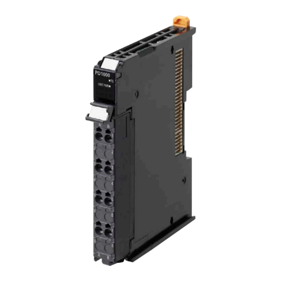
Appendices A-1-2 Additional NX Unit Power Supply Unit Description of Items on the Data Sheet of the Additional NX Unit Power Supply Unit The meanings of the items on the data sheet of the Additional NX Unit Power Supply Unit are explained in the table below. - Page 140 Appendices Additional NX Unit Power Supply Unit (Screwless Clamping Terminal Block, 12 mm Width) Unit name Additional NX Unit Power Supply Unit Model NX-PD1000 External connection ter- Screwless clamping terminal block (8 terminals) minals Power supply voltage 24 VDC (20.4 to 28.8 VDC) NX Unit power supply 10 W max.
- Page 141 Appendices Installation orientation Installation orientation: and restrictions • Connected to a CPU Unit Possible in upright installation. • Connected to a Communications Coupler Unit Possible in 6 orientations. Restrictions: As shown in the following. • For upright installation For 10 W output, 40°C Output power (W) For 8.5 W output, 55°C Ambient operating temperature (°C)
-
Page 142: A-1-3 Additional I/O Power Supply Unit
Appendices *1. You can use the unwired terminals of the Unit power supply terminals (UV/UG) for through-wiring of the Additional NX Unit Power Supply Unit, to other CPU Units to which NX Unit can be connected or to the Unit power supply terminals on another Communications Coupler Unit. - Page 143 Appendices Additional I/O Power Supply Units (Screwless Clamping Terminal Block, 12 mm Width) Unit name Additional I/O Power Supply Unit Model NX-PF0630 External connection ter- Screwless clamping terminal block (8 terminals) minals Power supply voltage 5 to 24 VDC (4.5 to 28.8 VDC) Maximum current of I/O power supply Current capacity of I/O...
- Page 144 Appendices Terminal connection dia- Additional I/O DC Input Unit gram Power Supply Unit NX-PD0630 Two-wire type 24 VDC Three-wire type Overload/low voltage Not supported. detection Protective function Not supported. *1. Use a voltage that is appropriate for the I/O circuits of the NX Units and the connected external devices. A - 8 NX-series System Units User’s Manual (W523)
- Page 145 Appendices Unit name Additional I/O Power Supply Unit Model NX-PF0730 External connection ter- Screwless clamping terminal block (8 terminals) minals Power supply voltage 5 to 24 VDC (4.5 to 28.8 VDC) Maximum current of I/O 10 A power supply Current capacity of I/O •...
- Page 146 Appendices Terminal connection dia- gram Additional I/O DC Input Unit Power Supply Unit NX-PF0730 Two-wire type 24 VDC Three-wire type Overload/low voltage Not supported. detection Protective function Not supported. *1. Use a voltage that is appropriate for the I/O circuits of the NX Units and the connected external devices. *2.
-
Page 147: A-1-4 I/O Power Supply Connection Unit
Appendices A-1-4 I/O Power Supply Connection Unit Description of Items on the Data Sheet of the I/O Power Supply Con- nection Unit The meanings of the items on the data sheet of the I/O Power Supply Connection Unit are explained in the table below. - Page 148 Appendices I/O Power Supply Connection Unit (Screwless Clamping Terminal Block, 12 mm Width) IOV Terminal Type Unit name I/O Power Supply Connection Unit Model NX-PC0020 External connection ter- Screwless clamping terminal block (16 terminals) minals Number of I/O power IOV: 16 terminals supply terminals Current capacity of I/O...
- Page 149 Appendices Terminal connection dia- gram I/O Power Supply DC Input Unit Connection Unit Three-wire type NX-PC0020 Transistor Output Unit A - 13 NX-series System Units User’s Manual (W523)
- Page 150 Appendices IOG Terminal Type Unit name I/O Power Supply Connection Unit Model NX-PC0010 External connection ter- Screwless clamping terminal block (16 terminals) minals Number of I/O power sup- IOG: 16 terminals ply terminals Current capacity of I/O 4 A/terminal max. power supply terminal Dimensions 12 (W) ×...
- Page 151 Appendices Terminal connection dia- gram I/O Power Supply DC Input Unit Connection Unit Three-wire type NX-PC0010 Transistor Output Unit A - 15 NX-series System Units User’s Manual (W523)
- Page 152 Appendices IOV/IOG Terminal Type Unit name I/O Power Supply Connection Unit Model NX-PC0030 External connection ter- Screwless clamping terminal block (16 terminals) minals Number of I/O power IOV: 8 terminals supply terminals IOG: 8 terminals Current capacity of I/O 4 A/terminal max.
- Page 153 Appendices Terminal connection dia- gram DC Input Unit I/O Power Supply Connection Unit Three-wire type Transistor Output Unit NX-PC0030 A - 17 NX-series System Units User’s Manual (W523)
-
Page 154: A-1-5 Shield Connection Unit
Appendices A-1-5 Shield Connection Unit Description of Items on the Data Sheet of the Shield Connection Unit The meanings of the items on the data sheet of the Shield Connection Unit are explained in the table below. Item Description Unit name The name of the Unit. - Page 155 Appendices Shield Connection Unit (Screwless Clamping Terminal Block, 12 mm Width) Unit name Shield Connection Unit Model NX-TBX01 External connection ter- Screwless clamping terminal block (16 terminals) minals Number of shield termi- 14 terminals (The following two terminals are functional ground terminals.) nals Dimensions 12 (W) ×...
- Page 156 Appendices Terminal connection dia- gram Shield Incremental Connection Unit Encoder NX-TBX01 Input Unit Shield (Open collector Rotary Encoder input) SHLD SHLD SHLD SHLD SHLD SHLD SHLD SHLD SHLD SHLD SHLD SHLD SHLD SHLD Ground of 100 Ω or less A - 20 NX-series System Units User’s Manual (W523)
-
Page 157: A-2 Dimensions
Appendices A-2 Dimensions A-2-1 Additional NX Unit Power Supply Unit, Additional I/O Power Sup- ply Unit, I/O Power Supply Connection Unit, and Shield Connec- tion Unit 12 mm Width 14.1 12.0 65.2 0.55 80.1 (Unit: mm) *1. The dimension is 1.35 mm for Units with lot numbers through December 2014. A - 21 NX-series System Units User’s Manual (W523) - Page 158 Appendices Installation Height (Unit: mm) A - 22 NX-series System Units User’s Manual (W523)
-
Page 159: A-3 List Of Nx Objects
Appendices A-3 List of NX Objects This section describes the NX objects of the System Units. The method to access NX objects through instructions or other messages depends on where the NX Unit is connected. If the NX Unit is connected to a CPU Unit, access is possible with the Read NX Unit Object instruction and the Write NX Unit Object instruction. -
Page 160: A-3-2 System Units
*3. The product codes are assigned for each product model. Bits 0 to 31: Product code *4. OMRON vendor code *5. Bits 24 to 31: Integer part of the Unit version. Bits 16 to 23: Fractional part of the Unit version. -
Page 161: List Of Screwless Clamping Terminal Block Models
Appendices A-4 List of Screwless Clamping Terminal Block Models This section explains how to read the screwless clamping terminal block models and shows the model table. A-4-1 Model Notation The screwless clamping terminal block models are assigned based on the following rules. N N X -T -T B Product type TB: Terminal block... -
Page 162: A-5 Version Information With Cpu Units
Appendices A-5 Version Information with CPU Units This section provides version-related information when connecting Units to a CPU Unit. This section describes the relationship between the unit versions of each Unit and the CPU Unit, and Sysmac Studio version. A-5-1 Relationship between Unit Versions of Units The relationship between the unit versions of each Unit and the CPU Unit, and Sysmac Studio version are indicated. -
Page 163: Version Information With Communications Coupler Units
Appendices A-6 Version Information with Communica- tions Coupler Units This section provides version-related information when connecting Units to a Communications Coupler Unit. Version information is provided for each Communications Coupler Unit that an NX Unit is connected to. A-6-1 Connection to an EtherCAT Coupler Unit The relationship between the unit versions of each Unit, EtherCAT Coupler Unit, CPU Unit and Industrial PC, and versions of the Sysmac Studio are shown below. -
Page 164: Connection To An Ethernet/Ip Coupler Unit
Appendices NX Unit Corresponding unit versions/versions EtherCAT CPU Unit or Model Unit version Sysmac Studio Coupler Unit Industrial PC NX-PD1000 Ver. 1.0 Ver. 1.0 Ver. 1.05 Ver. 1.06 NX-PF0630 NX-PF0730 Ver. 1.08 NX-PC0020 Ver. 1.06 NX-PC0010 NX-PC0030 NX-TBX01 A-6-2 Connection to an EtherNet/IP Coupler Unit The relationship between the unit versions of each Unit, EtherNet/IP Coupler Unit, CPU Unit and Indus- trial PC, and versions of the Sysmac Studio and NX-IO Configurator are shown below. - Page 165 Appendices NX Unit Corresponding unit versions/versions Application with an NJ/NX/NY-series Con- Application with a CS/CJ/CP-series PLC troller Unit Model CPU Unit or version NX-IO Con- EtherNet/IP Sysmac Stu- EtherNet/IP Sysmac Stu- Industrial Coupler Unit Coupler Unit figurator NX-PD1000 Ver. 1.0 Ver.
- Page 166 Appendices A - 30 NX-series System Units User’s Manual (W523)
- Page 167 Index I - 1 NX-series System Units User’s Manual (W523)
- Page 168 Index Index Access ................A-23 Log of Error ..............5-6 Additional I/O Power Supply Unit ......4-12, 4-18 Additional NX Unit Power Supply Unit ....4-11, 4-17 Applicable Wire ............4-39 Assumed cause .............. 5-7 Marker ................4-4 Marker attachment location ........3-2, 3-9 maximum current of I/O power supply ....
- Page 169 Index Unit ................A-23 Unit hookup guide ........... 3-2, 3-9 Unit Information Object ..........A-24 Unit power supply ..........4-9, 4-14 Unit power supply terminal ......4-9, 4-15, 4-22 Unit specifications ........... 3-2, 3-9 unit versions ..............24 unwired terminal ............4-22 Wiring Terminals ......4-22, 4-26, 4-33, 4-37, 4-38 I - 3 NX-series System Units User’s Manual (W523)
- Page 170 Index I - 4 NX-series System Units User’s Manual (W523)
- Page 172 The Netherlands Hoffman Estates, IL 60169 U.S.A. Tel: (31)2356-81-300/Fax: (31)2356-81-388 Tel: (1) 847-843-7900/Fax: (1) 847-843-7787 © OMRON Corporation 2013-2017 All Rights Reserved. OMRON (CHINA) CO., LTD. OMRON ASIA PACIFIC PTE. LTD. In the interest of product improvement, Room 2211, Bank of China Tower, No.