
Related Manuals for Omron NX-EC0112


Summary of Contents for Omron NX-EC0112
- Page 1 Machine Automation Controller NX-series Position Interface Units User’s Manual NX-EC0 NX-ECS NX-PG0 Incremental Encoder Input Units SSI Input Units Pulse Output Units W524-E1-05...
- Page 2 No patent liability is assumed with respect to the use of the information contained herein. Moreover, because OMRON is constantly striving to improve its high-quality products, the information contained in this manual is subject to change without notice. Every precaution has been taken in the preparation of this manual. Neverthe- less, OMRON assumes no responsibility for errors or omissions.
-
Page 3: Introduction
Applicable Products This manual covers the following product. • NX-series Position Interface Units Unit name Model Incremental Encoder Input Units NX-EC0112, NX-EC0122, NX-EC0132, NX-EC0142, NX-EC0212, and NX-EC0222 SSI Input Units NX-ECS112 and NX-ECS212 Pulse Output Unit NX-PG0112 and NX-PG0122 NX-series Position Interface Units User’s Manual (W524) -
Page 4: Table Of Contents
CONTENTS CONTENTS Introduction ......................1 Intended Audience............................1 Applicable Products ............................. 1 Relevant Manuals ..................... 8 Manual Structure ...................... 9 Page Structure and Icons ..........................9 Special Information ............................ 10 Precaution on Terminology ........................10 Terms and Conditions Agreement ................ 12 Warranty, Limitations of Liability ........................ - Page 5 CONTENTS System Configuration ......................1-9 1-2-1 System Configuration When Connecting to an NJ/NX-series Controller ........1-10 1-2-2 System Configuration When Connecting to a Controller Other Than the NJ/NX-series Controller........................... 1-11 Models ..........................1-13 1-3-1 Model Number Notation ......................1-13 1-3-2 List of Incremental Encoder Input Units ..................
- Page 6 6-4-1 Parts and Names ........................6-7 6-4-2 Functions of the Parts ......................... 6-8 6-4-3 Indicators............................. 6-9 Terminal Block Arrangement....................6-11 6-5-1 NX-EC0112 ..........................6-11 6-5-2 NX-EC0122 ..........................6-13 6-5-3 NX-EC0132 ..........................6-15 6-5-4 NX-EC0142 ..........................6-17 6-5-5 NX-EC0212 ..........................6-19 6-5-6 NX-EC0222 ..........................
- Page 7 CONTENTS 6-10 Specifications ........................6-77 6-10-1 General Specifications ......................6-77 6-10-2 Pulse Input Specifications ......................6-78 6-10-3 External Input Specifications ..................... 6-80 Section 7 SSI Input Units Interpreting Model Numbers....................7-3 System Configuration ......................7-4 Basic Application Procedures....................7-5 7-3-1 Procedures When Using the Motion Control Function Module ...........
- Page 8 CONTENTS Basic Application Procedures....................8-9 8-4-1 Procedures When Using the Motion Control Function Module ........... 8-9 8-4-2 Procedures When Not Using the Motion Control Function Module........... 8-10 Part Names and Functions ....................8-12 8-5-1 Parts and Names ........................8-12 8-5-2 Functions of the Parts .......................
- Page 9 CONTENTS Section 10 Troubleshooting 10-1 Checking for Errors......................10-2 10-2 Checking for Errors with the Indicators ................10-3 10-3 Checking for Errors and Troubleshooting on the Sysmac Studio........10-5 10-3-1 Checking for Errors from the Sysmac Studio ................10-5 10-3-2 Event Codes for Errors and Troubleshooting Procedures ............10-6 10-4 Resetting Errors ........................
-
Page 10: Relevant Manuals
Relevant Manuals Relevant Manuals The table below provides the relevant manuals for the NX-series Position Interface Units. Read all of the manuals that are relevant to your system configuration and application to make the most of the NX-series Position Interface Units. Other manuals, such as related product manuals, are necessary for specific system configurations and applications. -
Page 11: Manual Structure
Manual Structure Manual Structure Page Structure and Icons The following page structure and icons are used in this manual. Level 1 heading 4 Installation and Wiring Level 2 heading Level 3 heading Mounting Units Level 2 heading Gives the current Level 3 heading headings. -
Page 12: Special Information
Manual Structure Special Information Special information in this manual is classified as follows: Precautions for Safe Use Precautions on what to do and what not to do to ensure safe usage of the product. Precautions for Correct Use Precautions on what to do and what not to do to ensure proper operation and performance. Additional Information Additional information to read as required. - Page 13 Manual Structure NX-series Position Interface Units User’s Manual (W524)
-
Page 14: Terms And Conditions Agreement
Omron’s exclusive warranty is that the Products will be free from defects in materials and workman- ship for a period of twelve months from the date of sale by Omron (or such other period expressed in writing by Omron). Omron disclaims all other warranties, express or implied. -
Page 15: Application Considerations
Disclaimers Performance Data Data presented in Omron Company websites, catalogs and other materials is provided as a guide for the user in determining suitability and does not constitute a warranty. It may represent the result of Omron’s test conditions, and the user must correlate it to actual application requirements. Actual perfor- mance is subject to the Omron’s Warranty and Limitations of Liability. -
Page 16: Safety Precautions
Safety Precautions Safety Precautions Definition of Precautionary Information The following notation is used in this user’s manual to provide precautions required to ensure safe usage of an NX-series Position Interface Unit. The safety precautions that are provided are extremely important to safety. Always read and heed the information provided in all safety precautions. - Page 17 Safety Precautions Fail-safe Measures Provide safety measures in external circuits to ensure safety in the system if an abnormality occurs due to malfunction of the CPU Unit, other Units, or slaves or due to other external factors affecting operation. Not doing so may result in serious accidents due to incorrect operation. Emergency stop circuits, interlock circuits, limit circuits, and similar safety measures must be provided in external control circuits.
-
Page 18: Cautions
Safety Precautions Cautions Caution Wiring When you connect a computer or other peripheral device to a Communications Coupler Unit that has a non-isolated DC power supply, either ground the 0-V side of the external power supply (i.e. Unit power supply) or do not ground it at all. If the peripheral devices are grounded incorrectly, the external power supply (i.e. -
Page 19: Precautions For Safe Use
Precautions for Safe Use Precautions for Safe Use Transporting • When transporting any Unit, use the special packing box for it. Also, do not subject the Unit to excessive vibration or shock during transportation. • Do not drop any Unit or subject it to abnormal vibration or shock. Doing so may result in Unit malfunction or burning. - Page 20 Precautions for Safe Use • Do not write on the Communications Coupler Unit or an NX Unit with ink within the restricted region that is shown in the following figure. Also do not get this area dirty. When the Unit is installed or removed, ink or dirt may adhere to the pins in the NX bus connector, which may result in malfunctions in the Slave Terminal.
- Page 21 Precautions for Safe Use • Do not incline or twist the flat-blade screwdriver while it is in a release hole on a screwless clamping terminal block. Doing so may damage the terminal block. • Use crimp terminals for wiring the M3 screw terminal blocks. Do not connect bare stranded wires directly to the M3 screw terminal blocks.
- Page 22 Precautions for Safe Use Units that supply power continue to supply power to the Units for up to several seconds after the power supply is turned OFF. The PWR indicator remains lit as long as power is supplied. Confirm that the PWR indicator is not lit before you perform any of the above.
-
Page 23: Precautions For Correct Use
Precautions for Correct Use Precautions for Correct Use Storage, Mounting, and Wiring • Follow the instructions in this manual to correctly perform installation and wiring. • Do not operate or store the Units in the following locations. Doing so may result in malfunction, in operation stopping, or in burning. -
Page 24: Regulations And Standards
Concepts EMC Directives OMRON devices that comply with EC Directives also conform to the related EMC standards so that they can be more easily built into other devices or the overall machine. The actual products have been checked for conformity to EMC standards.*1 Whether the products conform to the standards in the system used by the customer, however, must be checked by the customer. -
Page 25: Conformance To Ul And Csa Standards
NX-series product must also comply with the standards, consult with your OMRON representative. Application conditions are defined according to the installation location. Application may not be possible for some installation locations. -
Page 26: Unit Versions
Gives the unit version of the Unit. Lot number Gives the lot number of the Unit. DDMYY: Lot number, : Used by OMRON. “M” gives the month (1 to 9: January to September, X: October, Y: November, Z: December) NX-series Position Interface Units User’s Manual (W524) - Page 27 Gives the lot number and unit version of the Unit. unit version • DDMYY: Lot number, : Used by OMRON. “M” gives the month (1 to 9: January to September, X: October, Y: November, Z: December) • 1: Unit version The decimal portion of the unit version is omitted.
-
Page 28: Unit Versions And Sysmac Studio Versions
Unit Versions • Unit model number • Unit version • Serial number • Lot number • Hardware version • Software version • Total power-ON time The software version is displayed only for Units that contain software. Version Information The total power-ON time is provided by function to monitor the total power-ON time. The func- tion to monitor the total power-ON time was added for a version upgrade. -
Page 29: Related Manuals
Related Manuals Related Manuals The following manuals are related. Use these manuals for reference. Manual name Cat. No. Model numbers Application Description NX-series Position Inter- W524 NX-EC0 Learning how to The hardware, setup, and functions for face Units User’s Man- use NX-series the NX-series Incremental Encoder NX-ECS... - Page 30 Related Manuals Manual name Cat. No. Model numbers Application Description NX-series CPU Unit W535 NX701- Learning the basic An introduction to the entire NX-series Hardware Use’s Manual specifications of system is provided along with the fol- the NX-series CPU lowing information on the CPU Unit. Units, including •...
- Page 31 Related Manuals Manual name Cat. No. Model numbers Application Description NJ/NX-series CPU Unit W507 NX701- Learning about The settings and operation of the CPU Motion Control User’s motion control set- Unit and programming concepts for NJ501- Manual tings and program- motion control are described.
-
Page 32: Terminology
Terminology Terminology Term Description axis A functional unit within the Motion Control Function Module. An axis is assigned to the drive mechanism in an external Servo Drive or the sensing mechanism in an external Encoder Input Slave Unit. axis variable A system-defined variable that is defined as a structure and provides status infor- mation and some of the axis parameters for an individual axis. -
Page 33: Revision History
September 2013 Added precautions for connecting to NJ-series Controllers and added information on time stamping. July 2014 Added the NX-EC0112, NX-EC0132, NX-EC0212, and NX-PG0112, and corrected mistakes. April 2015 • Made changes accompanying the upgrade to unit version 1.2. • Made revisions accompanying the addition of NX-series NX701-... - Page 34 Revision History NX-series Position Interface Units User’s Manual (W524)
-
Page 35: Sections In This Manual
Sections in this Manual Sections in this Manual Features and System Troubleshooting Configuration Specifications and Maintenance and Application Procedures Inspection Part Names and Appendices Functions Installation and Wiring Index I/O Refreshing Methods Incremental Encoder Input Units SSI Input Units Pulse Output Units Application Example NX-series Position Interface Units User’s Manual (W524) - Page 36 Sections in this Manual NX-series Position Interface Units User’s Manual (W524)
-
Page 37: Features And System Configuration
Features and System Configura- tion This section describes system configurations with Position Interface Units and the fea- tures and functions of Position Interface Units. 1-1 Features of Position Interface Units ....... 1-2 1-1-1 Introduction to Position Interface Units . -
Page 38: Features Of Position Interface Units
1 Features and System Configuration Features of Position Interface Units “NX-series Position Interface Unit” is a generic name for any of a group of NX Units that perform I/O processing of position data to perform positioning. The Position Interface Units use the Motion Control Function Module in an NJ/NX-series Controller (referred to as “MC Function Module”) to both perform pulse outputs and accept encoder inputs for motor control. - Page 39 1 Features and System Configuration Incremental Encoder Input Units An Incremental Encoder Input Unit converts pulse input signals from an incremental encoder and counts the number of pulses. Use an Incremental Encoder Input Unit to enable the Controller to identify control positions based on the number of encoder pulses.
- Page 40 1 Features and System Configuration SSI Input Units The SSI Input Units convert serial data from an SSI interface-compatible absolute encoder or linear encoder to obtain the absolute position. Use an SSI Input Unit to enable the Controller to identify control positions based on the absolute posi- tion information obtained from the target device.
- Page 41 1 Features and System Configuration Pulse Output Units A Pulse Output Unit performs pulse output for positioning commands sent to a stepper motor drive or other pulse input motor drive. Use a Pulse Output Unit to enable the Controller to perform positioning. You can also latch the pulse output value with an external input.
-
Page 42: Operation Of Position Interface Units
1 Features and System Configuration 1-1-3 Operation of Position Interface Units This section describes the operation of the Position Interface Units when you use them together with an NJ/NX-series Controller and the MC Function Module. You can use the Position Interface Units together with an NJ/NX-series Controller and the MC Function Module to perform the following control operations. - Page 43 1 Features and System Configuration In the NJ/NX-series Controller, the I/O refreshing processing, user program processing, and MC Func- tion Module processing between the Position Interface Units are executed in the primary periodic task and priority-5 periodic task. Refer to NJ/NX-series CPU Unit Software User's Manual (Cat. No. W501) for information on the pri- mary periodic task and priority-5 periodic task.
-
Page 44: Control Data For Position Interface Units
1 Features and System Configuration 1-1-4 Control Data for Position Interface Units Some of the functions of the Position Interface Units are based on the CiA402 drive profile. The I/O data definitions and operations for interaction with the Controller are based on functions in the CiA402 drive profile. -
Page 45: System Configuration
1 Features and System Configuration System Configuration You can mount NX-series Position Interface Units after an EtherCAT Coupler Unit, the Communications Coupler Unit, in an EtherCAT Slave Terminal. This allows you to connect to a controller that provides an EtherCAT master. The system configuration and the functions of the Position Interface Units that you can use depend on the controller that you connect to and the EtherCAT master specifications. -
Page 46: System Configuration When Connecting To An Nj/Nx-Series Controller
1 Features and System Configuration 1-2-1 System Configuration When Connecting to an NJ/NX-series Con- troller To use the Position Interface Units, mount them on an EtherCAT Slave Terminal and connect the Slave Terminal to the built-in EtherCAT port on an NJ/NX-series CPU Unit. In this configuration, you can use the MC Function Module of the NJ/NX-series Controller to perform motion control. -
Page 47: System Configuration When Connecting To A Controller Other Than The Nj/Nx-Series Controller
(100BASE-TX) or higher, and use straight wiring. (Ethernet cable) *1. An EtherCAT Slave Terminal cannot be connected to any of the OMRON CJ1W-NC[]81/[]82 Position Control Units even though they can operate as EtherCAT masters. 1-2-2 System Configuration When Connecting to a Controller Other... - Page 48 You can load the ESI file into the Controller or the Sysmac Studio to easily allocate Slave Terminal process data and make other settings. The ESI files for OMRON EtherCAT slaves are installed in the Sysmac Studio. You can obtain the ESI files for the latest models through the Sysmac Studio’s automatic update function.
-
Page 49: Models
Number of External Fre- I/O refreshing Number of I/O Model Remarks inputs quency methods entry mappings channels NX-EC0112 1 (NPN) 3 (NPN) 500 kHz • Free-Run refreshing Inputs: 1, 24-V voltage Outputs: 1 input NX-EC0122 1 (PNP) 3 (PNP) • Synchronous I/O... -
Page 50: List Of Ssi Input Units
1 Features and System Configuration 1-3-3 List of SSI Input Units The following table lists the different models of the SSI Input Units. Refer to 7-1 Interpreting Model Numbers on page 7-3 for information on SSI Input Units. Maxi- Number of Number of External Model... -
Page 51: Functions
I/O refreshing method is set to synchronous I/O refreshing. *1. You can use external inputs only with the following single-counter-channel models: NX-EC0112, NX-EC0122, NX-EC0132, and NX-EC0142. You cannot use external inputs with the NX-EC0212 or NX-EC0222 because it has 2 counter channels. - Page 52 Remarks Phase-Z External External External operation input input 1 input 2 input 3 commands NX-EC0112 NX-EC0122 NX-EC0132 NX-EC0142 NX-EC0212 The EC0212 does not have external inputs. NX-EC0222 The EC0222 does not have external inputs. Functions and Assignable Commands/Inputs The commands and inputs that you can assign depend on the function.
-
Page 53: Functions Of Ssi Input Units
1 Features and System Configuration 1-4-2 Functions of SSI Input Units The following table lists the functions of the SSI Input Units. Refer to 7-9 Functions on page 7-38 for details on these functions. Function Description SSI data settings Allows you to set the bit position and data length for each counter based on the format of the SSI data. -
Page 54: Functions Of The Pulse Output Unit
1 Features and System Configuration 1-4-3 Functions of the Pulse Output Unit The following table lists the functions of the Pulse Output Unit. Refer to 8-10 Functions on page 8-52 for details on these functions. Function Description Pulse output method Allows you to select either forward/reverse direction pulse outputs or pulse + direction outputs for the pulse output method. -
Page 55: Support Software
1 Features and System Configuration Support Software Support Software is required to configure a system that uses NX-series Position Interface Units. 1-5-1 Applicable Support Software The Support Software that you can use depends on the system configuration. Select the right Support Software for your system configuration. - Page 56 1 Features and System Configuration To set up the Unit configuration information and NX Unit settings of the Slave Terminal, connect the Sysmac Studio to the EtherCAT Coupler Unit through the USB port. Use Sysmac Studio version 1.06 or higher. Refer to the Sysmac Studio Version 1 Operation Manual (Cat.
-
Page 57: Specifications And Application Procedures
Specifications and Application Procedures This section provides the specifications of the Position Interface Units and describes how to use the Position Interface Units. 2-1 Specifications ..........2-2 2-1-1 General Specifications for the Position Interface Units . -
Page 58: Specifications
Listed (UL 508), ANSI/ISA 12.12.01, Applicable standards EC: EN 61131-2, C-Tick, KC (KC Registration), NK, and LR *1. Refer to the OMRON Industrial Automation website (http://www.ia.omron.com/) or consult your OMRON rep- resentative for the most recent applicable standards for each model. 2-1-2... -
Page 59: Operating Procedures
2 Specifications and Application Procedures Operating Procedures The operating procedures for the Position Interface Units depend on the system configuration. For example, even when you use an NJ/NX-series Controller, the operating procedures depend on whether the MC Function Module is also used. This section describes the basic operating procedures that are required to use the Units. - Page 60 2 Specifications and Application Procedures Basic Flow of Operation The following figure shows the basic flow of operation: START Create a project. Setup Create the EtherCAT network configuration. EtherCAT Slave Terminal Configu- Create the NX Unit configuration. ration and Settings on page 2-5 Parameter Settings of the Position Set the NX Unit parameters.
- Page 61 2 Specifications and Application Procedures Procedures When Using the MC Function Module This section describes the procedures to use Position Interface Units with the MC Function Module. For details on procedures for which references are not specified, refer to the NJ/NX-series CPU Unit Motion Control User's Manual (Cat.
- Page 62 2 Specifications and Application Procedures Assigning Axes Assign the Position Interface Units to Axis Variables. Use the following procedure to make the assignments. Right-click an axis in the Multiview Explorer and select Edit from the menu. The Axis Basic Settings are displayed in the Axis Parameter Settings Tab Page. 2 - 6 NX-series Position Interface Units User’s Manual (W524)
- Page 63 2 Specifications and Application Procedures Select Motion Control. You can assign processing to either the primary periodic task or priority-5 periodic task. Additional Information This setting applies to an NX-series CPU Unit. NJ-series CPU Units do not have this setting. Select the axis type.
- Page 64 2 Specifications and Application Procedures Select the devices to use as the input and output devices. This operation enables you to use an NX Unit as an axis. The following table lists the NX Units that you can select for each device. Axis type Device type Selectable NX Units...
- Page 65 2 Specifications and Application Procedures Function Settings of MC Function Module For details on the function settings of the MC Function Module, refer to the NJ/NX-series CPU Unit Motion Control User's Manual (Cat. No. W507). Also refer to 8-9-2 Precautions When Using the Pulse Output Unit on page 8-42. Precautions for Correct Use If you assign an NX Unit connected to an EtherCAT Coupler Unit as an I/O device for a MC Function Module axis, the MC Function Module manages refreshing of the I/O data.
-
Page 66: Procedures When Not Using The Motion Control Function Module
2 Specifications and Application Procedures 2-2-2 Procedures When Not Using the Motion Control Function Module This section describes the basic operating procedures that are required when you do not use the MC Function Module with an NJ/NX-series Controller. If you do not want to use the MC Function Module, you can only use basic instructions in your pro- grams, including those for position management. - Page 67 2 Specifications and Application Procedures Basic Flow of Operation The following figure shows the basic flow of operation: START Create a project. Setup Create the EtherCAT network configuration. EtherCAT Slave Terminal Configuration Create the NX Unit configuration. and Settings on page 2-12 Parameter Settings of the Position Inter- Set the NX Unit parameters.
- Page 68 2 Specifications and Application Procedures Procedures When Not Using the MC Function Module This section describes the procedures to use Position Interface Units without the MC Function Module. EtherCAT Slave Terminal Configuration and Settings Mount the Position Interface Units after an EtherCAT Coupler Unit to configure an EtherCAT Slave Terminal.
-
Page 69: Using An Ethernet/Ip Coupler Unit
2 Specifications and Application Procedures 2-2-3 Using an EtherNet/IP Coupler Unit Mount the Position Interface Units after an EtherNet/IP Coupler Unit to configure an EtherNet/IP Slave Terminal. To use the Position Interface Units, you must configure the EtherNet/IP network and configure and set the EtherNet/IP Slave Terminal. - Page 70 2 Specifications and Application Procedures 2 - 14 NX-series Position Interface Units User’s Manual (W524)
-
Page 71: Part Names And Functions
Part Names and Functions This section describes the names and functions of the parts of the Position Interface Units. 3-1 Parts and Names ..........3-2 3-2 Indicators . -
Page 72: Parts And Names
Letter Name Function Marker attachment locations This is where the markers are attached. OMRON markers are pre-installed at the factory. You can also install commercially available markers. NX bus connector This connector is used to connect to another Unit. Unit hookup guides These guides are used to connect two Units to each other. -
Page 73: Indicators
3 Part Names and Functions Indicators This section provides information on the indicators that are provided on all Position Interface Units. Refer to the following sections for indicator information specific to each Unit: 6-4-3 Indicators on page 6-9, 7-4-3 Indicators on page 7-9, and 8-5-3 Indicators on page 8-13. A Position Interface Unit has indicators that show information such as the current operating status of the Unit or signal I/O status details. - Page 74 3 Part Names and Functions TS Indicator This indicator shows information such as the current status of the Position Interface Unit or of the network. TS indicator The following table lists the possible states for this indicator and what they mean. Color Status Description...
-
Page 75: Terminal Blocks
3 Part Names and Functions Terminal Blocks Position Interface Units use screwless clamping terminal blocks for easy wiring and removal. In terms of the number of terminals, there are three types of terminal blocks used on Position Interface Units: one with 12 terminals, one with 16 terminals, and one with 24 terminals (using 2 sets of 12-termi- nal terminal blocks), as shown below. - Page 76 The following table gives the Terminal Blocks that are applicable to each Unit. Terminal Block Unit model Terminal Block model num- Ground terminal Terminal current number No. of terminals mark capacity NX-EC0112 NX-TBA161 None NX-TBA162 10 A NX-EC0122 NX-TBA161 NX-TBA162 10 A NX-EC0132...
- Page 77 3 Part Names and Functions Precautions for Correct Use You can mount an NX-TB1 or NX-TB2 Terminal Block to a Position Interface Unit. Even if you mount an NX-TB2 Terminal Block, which has a terminal current capacity of 10 A, the rated current does not change because the current capacity specification of the I/O power supply terminals on a Position Interface Unit is 4 A max.
- Page 78 3 Part Names and Functions 3 - 8 NX-series Position Interface Units User’s Manual (W524)
-
Page 79: Installation And Wiring
Installation and Wiring This section describes how to install and wire Position Interface Units. 4-1 Installing Units ..........4-2 4-1-1 Installing Position Interface Units . -
Page 80: Installing Units
4 Installation and Wiring Installing Units This section describes how to install and remove NX Units, such as Position Interface Units, and how to attach markers. Refer to the NX-series EtherCAT Coupler Unit User’s Manual (Cat. No. W519) for information on prep- arations for installation and installation in a control panel. - Page 81 4 Installation and Wiring • Do not write anything with ink within the restricted region that is shown in the following figure. Also do not get this area dirty. When the Unit is installed or removed, ink or dirt may adhere to the pins in the NX bus connector, which may result in malfunctions in the Slave Terminal.
- Page 82 4 Installation and Wiring Slide the NX Unit in on the hookup guides. Press the NX Unit with a certain amount of force against the DIN Track until you hear the DIN Track mounting hook lock into place. It is not necessary to release the DIN Track mounting hook on the Position Interface Unit when you mount the Position Interface Unit.
-
Page 83: Attaching Markers
Attaching Markers You can attach markers to NX Units and terminal blocks to identify them. The plastic markers made by OMRON are installed for the factory setting. The ID information can be written on them. Commercially available markers can also be installed. -
Page 84: Removing Position Interface Units
4 Installation and Wiring 4-1-3 Removing Position Interface Units This section describes how to remove NX Units, such as Position Interface Units. Use a flat-blade screwdriver or similar tool to pull up the DIN Track mounting hook on the NX Unit to remove. -
Page 85: Installation Orientation
4 Installation and Wiring 4-1-4 Installation Orientation The Slave Terminal can be installed in any of the following six orientations. (A) is the upright installation orientation and (B) to (F) are installation orientations other than upright. Down However, there are restrictions on the installation orientation and restrictions to the specifications that can result from the Communications Coupler Units and NX Units that are used. -
Page 86: Connecting The Power Supply And Ground Wires
4 Installation and Wiring Connecting the Power Supply and Ground Wires This section provides information on wiring the power supplies for Position Interface Units. 4-2-1 Power Supply Types There are the following two types of power supplies that supply power to the Position Interface Units. Power supply Description name... - Page 87 4 Installation and Wiring The following examples show the wiring for these power supplies. Example: Incremental Encoder Input Unit Additional I/O Incremental Encoder Power Supply Unit Input Unit Encoder 1 I/O power supply (24 VDC) To next Unit Encoder 2 Communications Coupler Unit Additional I/O...
-
Page 88: Calculating The Total Current Consumption From I/O Power Supply
Refer to the NX-series System Unit User’s Manual (Cat. No. W523) for the specifications of these Units. For a complete list of the latest power supply Units in the NX Series, refer to the product catalog or offi- cial website, or contact your OMRON sales representatives. The following sections describe each of these Units. - Page 89 4 Installation and Wiring Additional NX Unit Power Supply Unit This NX Unit provides additional NX Unit power supply. This NX Unit is used when the total power consumption of the NX Units in the Slave Terminal exceeds the NX Unit power supply capacity of the Communications Coupler Unit. The NX Unit power supply provides power for the internal circuits in each NX Unit.
- Page 90 4 Installation and Wiring Separating the I/O Power Supply • The Additional I/O Power Supply Unit is used when the connected external devices have different I/O power supply voltages. • The Additional I/O Power Supply Unit is used to separate the power supply systems. I/O power supply I/O power...
- Page 91 4 Installation and Wiring I/O Power Supply Connection Units Use this Unit when you connect Position Interface Units or other NX Units to external devices and there are not enough I/O power supply terminals. I/O Power Supply Communications Connection Units Additional NX Unit Coupler Unit NX Units...
-
Page 92: Wiring With Shielded Cables
Wiring Examples for Incremental Encoder Input Units NX-EC0112 or NX-EC0122 The following wiring example shows an NX-EC0112 or NX-EC0122 Incremental Encoder Input Unit wired to a rotary encoder with a shielded cable. The shield is connected to the Shield Connection Unit (NX-TBX01). - Page 93 4 Installation and Wiring NX-EC0132 or NX-EC0142 The following wiring example shows an NX-EC0132 or NX-EC0142 Incremental Encoder Input Unit wired to a rotary encoder with a shielded cable. The shield is connected to the Shield Connection Unit (NX-TBX01). Incremental Encoder Input Unit Rotary encoder...
- Page 94 4 Installation and Wiring Wiring Examples for SSI Input Units NX-ECS112 The following wiring example shows an NX-ECS112 SSI Input Unit wired to a rotary encoder with a shielded cable. The shield is connected to the Shield Connection Unit (NX-TBX01). Shield SSI Input Unit Shield...
- Page 95 4 Installation and Wiring Wiring Example for Pulse Output Units NX-PG0112 The following wiring example shows an NX-PG0112 Pulse Output Unit wired to a drive with a shielded cable. The shield is connected to the Shield Connection Unit (NX-TBX01). Stepper motor Pulse Output Unit Shield...
- Page 96 4 Installation and Wiring NX-PG0122 The following wiring example shows an NX-PG0122 Pulse Output Unit wired to a drive with a shielded cable. The shield is connected to the Shield Connection Unit (NX-TBX01). Stepper motor Pulse Output Unit Shield Shield Connection Unit Drive...
-
Page 97: Wiring The Terminals
4 Installation and Wiring Wiring the Terminals This section provides information on wiring the terminals on Position Interface Units. WARNING Make sure that the voltages and currents that are input to the Units and slaves are within the specified ranges. Inputting voltages or currents that are outside of the specified ranges may cause accidents or fire. - Page 98 4 Installation and Wiring Wiring Terminals This section describes wiring for the following terminals: • I/O power supply terminals • I/O terminals Applicable Wires You can connect twisted wires, solid wires, or ferrules attached to twisted wires to the screwless clamp- ing terminal block.
- Page 99 4 Installation and Wiring The applicable ferrules, wires, and crimping tool are given in the following table. Applicable Ferrule Terminal Manufac- model Crimping tool wire (mm type turer number (AWG)) All terminals Phoenix AI0,34-8 0.34 (#22) Phoenix Contact (Applicable wire sizes are given except Contact in parentheses.)
- Page 100 4 Installation and Wiring Terminals Wire type Wire plating Conductor Wire size length (strip- Classifica- Current Twisted Solid Plated Unplated ping length) tion capacity wires wire All terminals 2 A max. Possible Possi- Possi- Possible 8 to 10 mm 0.08 to 1.5 mm except Greater than Not possi-...
- Page 101 4 Installation and Wiring Connecting and Removing Wires This section describes how to connect and remove wires. Terminal Block Parts and Names Release hole Terminal hole Required Tools A flat-blade screwdriver is used to connect and remove wires. Use the following type of flat-blade screwdriver.
- Page 102 4 Installation and Wiring Connecting Twisted and Solid Wires Use the following procedure to connect twisted and solid wires to the terminal block. Press the flat-blade screwdriver diagonally into the release hole. The optimal angle for insertion is between 10° to 15°. If the screwdriver is inserted correctly, you should feel resistance from the spring inside the release hole.
- Page 103 4 Installation and Wiring Removing Wires Use the following procedure to remove wires from the terminal block. The removal process is the same for both ferrules and twisted/solid wires. Press the flat-blade screwdriver diagonally into the release hole. The optimal angle for insertion is between 10° to 15°. If the screwdriver is inserted correctly, you should feel resistance from the spring inside the release hole.
- Page 104 4 Installation and Wiring Removing a Terminal Block Press the lock lever on the terminal block and pull out the top of the terminal block to remove it. Lock lever Terminal block Attaching a Terminal Block Mount the terminal block hook on the guide at the bottom of the NX Unit, lift up the terminal block, and press in on the top of the terminal block until you hear it engage.
-
Page 105: Preventing Incorrect Attachment Of Terminal Blocks
4 Installation and Wiring 4-3-2 Preventing Incorrect Attachment of Terminal Blocks You can limit the possible Position Interface Unit and terminal block combinations to prevent uninten- tionally connecting the wrong terminal block. Insert three Coding Pins (NX-AUX02) into three of the six incorrect attachment prevention holes on the terminal block and the Position Interface Unit. - Page 106 1 through 6 in the figure below. As shown in the following table, there are 20 unique pin patterns that you can use. Terminal Block Unit Holes used by Holes used by OMRON OMRON Incorrect Incorrect attachment attachment...
- Page 107 • The holes not designated by the numbers 1 through 6 in the above figure are used by OMRON. If you insert any Coding Pins into the holes reserved for use by OMRON, you will not be able to mount the terminal block to the Unit.
- Page 108 4 Installation and Wiring Unit 4 - 30 NX-series Position Interface Units User’s Manual (W524)
-
Page 109: Wiring Precautions
4 Installation and Wiring Wiring Precautions Electronic control equipment may malfunction due to noise from surrounding power supply lines and external loads. Malfunctions due to noise are difficult to reproduce, and it can take some time to determine what the cause of the problem is. - Page 110 4 Installation and Wiring Additional Information • Place the diode for absorbing surge or surge absorber next to the relay. Use a diode for absorbing surge that can withstand at least 5 times the circuit voltage. • Noise on the power supply line may affect operation if you also use the same power supply to power an electrical welder or electric discharge machine, or if there is any source of high-fre- quency noise nearby.
-
Page 111: Checking Wiring
4 Installation and Wiring Checking Wiring Use the functionality of the Sysmac Studio to check the wiring. The procedure depends on whether the MC Function Module is used. Procedures When Using the MC Function Module When the MC Function Module is used to control motion, use the MC Test Run and axis status monitor (MC monitor table) functions of the Sysmac Studio. - Page 112 4 Installation and Wiring Precautions for Correct Use A Pulse Output Unit outputs pulses in one control period equivalent to the deviation between the implemented command position and the command current position. For the Velocity-contin- uous Pulse Output Method, pulses are output according to the implemented command velocity. Therefore, observe the following precautions if you check the pulse output without using the MC Function Module.
-
Page 113: Wiring Examples
4 Installation and Wiring Wiring Examples Refer to the following sections for terminal wiring examples for the Position Interface Units: 6-5 Termi- nal Block Arrangement on page 6-11, 7-5 Terminal Block Arrangement on page 7-10, and 8-6 Terminal Block Arrangement on page 8-14. 4 - 35 NX-series Position Interface Units User’s Manual (W524) - Page 114 4 Installation and Wiring 4 - 36 NX-series Position Interface Units User’s Manual (W524)
-
Page 115: I/O Refreshing Methods
I/O Refreshing Methods This section describes the I/O refreshing methods and functions for Position Interface Units. 5-1 I/O Refreshing for Slave Terminals ....... . 5-2 5-2 I/O Refreshing Methods . -
Page 116: I/O Refreshing For Slave Terminals
5 I/O Refreshing Methods I/O Refreshing for Slave Terminals This section first describes I/O refreshing for NX-series Slave Terminals. It then describes operation when the built-in EtherCAT port on the NJ/NX-series CPU Unit is used for communications with an EtherCAT Slave Terminal. I/O Refreshing from the CPU Unit to the Slave Terminals The CPU Unit performs I/O refreshing cyclically with the Slave Terminals through the Communications Master Unit and the Communications Coupler Unit. - Page 117 5 I/O Refreshing Methods NJ-series CPU Units and I/O Refresh Operation The operation of I/O refreshing is as follows when the built-in EtherCAT port on the NJ-series CPU Unit is used for communications with an EtherCAT Slave Terminal. • The (b) process data communications cycle and (c) refresh cycle of the NX bus in the above figure are automatically synchronized with the (a) task period of the primary periodic task in the CPU Unit if the distributed clock is enabled in the EtherCAT Coupler Unit.
-
Page 118: I/O Refreshing Methods
5 I/O Refreshing Methods I/O Refreshing Methods This section describes I/O refreshing for Position Interface Units. 5-2-1 I/O Refreshing Methods The I/O refreshing methods that you can use between the Communications Coupler Unit and the NX Units depend on the Communications Coupler Unit that you use. EtherCAT Coupler Unit The I/O refreshing methods that you can use between an EtherCAT Coupler Unit and the Position Inter- face Units when the EtherCAT Coupler Unit is connected to the built-in EtherCAT port on an... -
Page 119: I/O Refreshing Method Operation
5 I/O Refreshing Methods EtherCAT Coupler Unit The I/O refreshing method between the EtherCAT Coupler Unit and the Position Interface Units depends on the Enable Distributed Clock setting in the EtherCAT Coupler Unit. Enable Distributed Clock setting Position Interface Units in the EtherCAT Coupler Unit Enabled (DC for synchronization) Operates with synchronous I/O refreshing... - Page 120 5 I/O Refreshing Methods • The ON/OFF response time is required from when outputs are updated until the output status is set on the external terminals of the NX Units. Input Units (a) Inputs are refreshed in order for each Unit. (d) The interval for reading inputs is not constant.
- Page 121 5 I/O Refreshing Methods Operation of Synchronous I/O Refreshing The NX Units that use synchronous I/O refreshing in an EtherCAT Slave Terminal receive inputs at a set fixed interval based on the synchronization timing. Outputs are also refreshed simultaneously, but at a separately set timing from inputs.
- Page 122 5 I/O Refreshing Methods Synchronous Input Refreshing • The NX Units that operate with synchronous input refreshing in a Slave Terminal read inputs at a fixed interval based on Sync0. (Refer to figure (a) in the diagram below.) Refer to the NX-series EtherCAT Coupler Unit User’s Manual (Cat. No. W519-E1-05 or later) for information on the Slave Terminals that operate with the same timing when more than one Slave Ter- minal is placed on the same EtherCAT network.
- Page 123 5 I/O Refreshing Methods Synchronous Output Refreshing • The NX Units that operate with synchronous output refreshing in a Slave Terminal update outputs at a fixed interval based on Sync0. (Refer to figure (a) in the diagram below.) Refer to the NX-series EtherCAT Coupler Unit User’s Manual (Cat. No. W519-E1-05 or later) for information on the Slave Terminals that operate with the same timing when more than one Slave Ter- minal is placed on the same EtherCAT network.
- Page 124 5 I/O Refreshing Methods Operation for Task Period Prioritized Refreshing With task period prioritized refreshing, shortening the task period is given priority over synchronizing the I/O timing with other NX Units that use synchronous I/O refreshing. Input Prioritized Refreshing •...
- Page 125 5 I/O Refreshing Methods Output Prioritized Refreshing • Output processing is started on Sync0. (See following figure (a).) • The Communications Coupler Unit updates the values of the output during I/O refreshing. (See following figure (b).) • The I/O refreshing interval changes according to the processing conditions of the Communica- tions Coupler Unit and host communications master (see following figure (c)).
- Page 126 5 I/O Refreshing Methods 5 - 12 NX-series Position Interface Units User’s Manual (W524)
- Page 127 NX-EC0112 ........
- Page 128 6 Incremental Encoder Input Units 6-9-1 Parameters ........... . 6-46 6-9-2 Counter Type .
-
Page 129: Interpreting Model Numbers
6 Incremental Encoder Input Units Interpreting Model Numbers The model number of an Incremental Encoder Input Unit tells you the Unit type, number of axes, I/O specifications, and other information. NX-EC0 1 2 2 NX Series Unit Type EC0: Incremental Encoder Input Unit Number of Channels 1: 1 channel 2: 2 channels... -
Page 130: System Configuration
6 Incremental Encoder Input Units System Configuration The following figure shows the system configuration of an Incremental Encoder Input Unit. Symbol Description Support Software (Sysmac Studio) Connection to the peripheral USB port or built-in EtherNet I/P port on an NJ/NX-series CPU Unit EtherCAT master (NJ/NX-series CPU Unit) EtherCAT communications cable EtherCAT Coupler Unit... -
Page 131: Basic Application Procedures
6 Incremental Encoder Input Units Basic Application Procedures This section describes the basic procedures to use an Incremental Encoder Input Unit. The procedure depends on whether the MC Function Module is used. 6-3-1 Procedures When Using the Motion Control Function Module The process flow to use an Incremental Encoder Input Unit with the MC Function Module is shown below. -
Page 132: Procedures When Not Using The Motion Control Function Module
6 Incremental Encoder Input Units Operate the Controller and the machine. Operation Maintenance Perform periodic maintenance. *1. Refer to 4-5 Checking Wiring on page 4-33 for the checking procedures. 6-3-2 Procedures When Not Using the Motion Control Function Module The process flow to use an Incremental Encoder Input Unit without the MC Function Module is shown below. -
Page 133: Part Names And Functions
6-4-1 Parts and Names Units with voltage inputs and Units with line receiver inputs have different shapes. Units with Voltage Inputs The names of the parts of the NX-EC0112, NX-EC0122, NX-EC0212,and NX-EC0222 are shown in the following figure. Symbol Name... -
Page 134: Functions Of The Parts
The names of the parts of the NX-EC0132 and NX-EC0142 are shown in the following figure. Symbol Name Function Marker attachment This is where the markers are attached. OMRON markers are pre-installed locations at the factory. You can also install commercially available markers. NX bus connector This connector is used to connect to another Unit. -
Page 135: Indicators
Refer to 3-2 Indicators on page 3-3 for information on the indicators that are provided on all Position Interface Units. NX-EC0112 and NX-EC0122 The indicators for a One-input Unit with a voltage input are described in the following table. Indicator... - Page 136 6 Incremental Encoder Input Units NX-EC0132 and NX-EC0142 The indicator for a One-input Unit with a line receiver input is described in the following table. Indicator Name Color Status Description Counter operation sta- Green Lit The counter is enabled. tus indicator Not lit The counter is disabled.
-
Page 137: Terminal Block Arrangement
This section describes the terminal block arrangements of the Units. 6-5-1 NX-EC0112 This section provides diagrams of the terminal block arrangement and internal power supply wiring of the NX-EC0112. It also provides a wiring example. Terminal Block Arrangement A 16-terminal terminal block is used. Terminal No. - Page 138 6 Incremental Encoder Input Units Internal Power Supply Wiring Diagram The following diagram shows the internal power supply wiring. Incremental Encoder Input Unit Terminal block Note The I/O power is supplied from the I/O power supply con- nected to the I/O power supply terminals on the Communica- tions Coupler Unit or an Additional I/O Power Supply Unit.
-
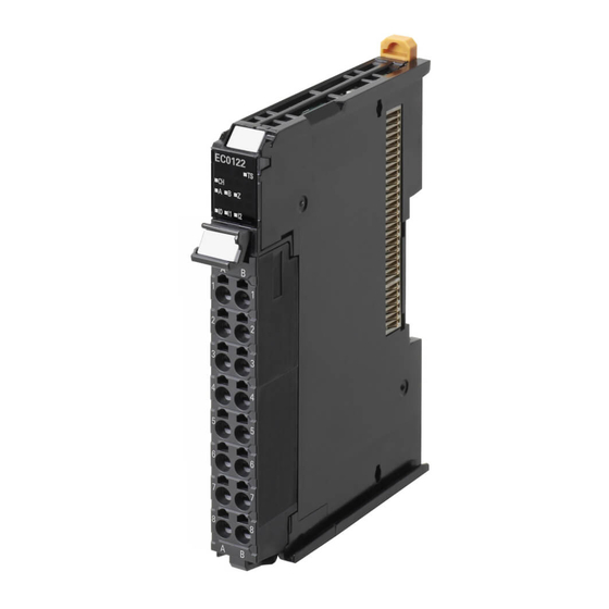
Page 139: Nx-Ec0122
6 Incremental Encoder Input Units 6-5-2 NX-EC0122 This section provides diagrams of the terminal block arrangement and internal power supply wiring of the NX-EC0122. It also provides a wiring example. Terminal Block Arrangement A 16-terminal terminal block is used. Terminal No. Symbol Name Counter input A... - Page 140 6 Incremental Encoder Input Units Wiring Example The following is a wiring example. Incremental Encoder Input Unit Additional I/O Power Supply Unit Encoder I/O power supply (24 VDC) Sensor 1 Sensor 2 Sensor 3 Note 1. The encoder and external inputs on Units with voltage inputs are PNP connections. 2.
-
Page 141: Nx-Ec0132
6 Incremental Encoder Input Units 6-5-3 NX-EC0132 This section provides diagrams of the terminal block arrangement and internal power supply wiring of the NX-EC0132. It also provides a wiring example. Terminal Block Arrangement Two 12-terminal terminal blocks are used. Terminal No. Symbol Name External input 0... - Page 142 6 Incremental Encoder Input Units Internal Power Supply Wiring Diagram The following diagram shows the internal power supply wiring. Incremental Encoder Input Unit Terminal block NX bus connector 24 V Note 1. The I/O power is supplied from the I/O power supply connected to the I/O power supply terminals on the Communications Coupler Unit or an Additional I/O Power Supply Unit.
-
Page 143: Nx-Ec0142
6 Incremental Encoder Input Units 6-5-4 NX-EC0142 This section provides diagrams of the terminal block arrangement and internal power supply wiring of the NX-EC0142. It also provides a wiring example. Terminal Block Arrangement Two 12-terminal terminal blocks are used. Terminal No. Symbol Name External input 0... - Page 144 6 Incremental Encoder Input Units Internal Power Supply Wiring Diagram The following diagram shows the internal power supply wiring. Incremental Encoder Input Unit Terminal block NX bus connector 24 V Note 1. The I/O power is supplied from the I/O power supply connected to the I/O power supply terminals on the Communications Coupler Unit or an Additional I/O Power Supply Unit.
-
Page 145: Nx-Ec0212
6 Incremental Encoder Input Units 6-5-5 NX-EC0212 This section provides diagrams of the terminal block arrangement and internal power supply wiring of the NX-EC0212. It also provides a wiring example. Terminal Block Arrangement A 12-terminal terminal block is used. Terminal No. Symbol Name Counter 1 input A... - Page 146 6 Incremental Encoder Input Units Wiring Example The following is a wiring example. Incremental Encoder Input Unit Additional I/O Power Supply Unit Encoder 1 I/O power supply (24 VDC) Encoder 2 Note 1. The encoder inputs on Units with voltage inputs are NPN connections. 2.
-
Page 147: Nx-Ec0222
6 Incremental Encoder Input Units 6-5-6 NX-EC0222 This section provides diagrams of the terminal block arrangement and internal power supply wiring of the NX-EC0222. It also provides a wiring example. Terminal Block Arrangement A 12-terminal terminal block is used. Terminal No. Symbol Name Counter 1 input A... - Page 148 6 Incremental Encoder Input Units Wiring Example The following is a wiring example. Incremental Encoder Input Unit Additional I/O Power Supply Unit Encoder 1 I/O power supply (24 VDC) Encoder 2 Note 1. The encoder inputs on Units with voltage inputs are PNP connections. 2.
-
Page 149: I/O Refreshing Method Setting
6 Incremental Encoder Input Units I/O Refreshing Method Setting There are the following methods to exchange data between Incremental Encoder Input Units and the Controller: Free-Run refreshing, synchronous I/O refreshing, and task period prioritized refreshing. This section describes how to set the I/O refreshing method for Incremental Encoder Input Units, the I/O refreshing methods, and the differences in I/O refreshing methods for different Controllers. -
Page 150: Free-Run Refreshing
6 Incremental Encoder Input Units Precautions for Correct Use • If you use a Position Interface Unit and EtherCAT Coupler Unit together and you use Free-Run refreshing, set the task period to a value that is greater than or equal to the refresh cycle of the Position Interface Unit. - Page 151 6 Incremental Encoder Input Units Setting with the Sysmac Studio Use the following procedure to select Disabled (FreeRun) from the Enable Distributed Clock setting for the EtherCAT Coupler Unit and use Free-Run refreshing for Incremental Encoder Input Units con- nected to an EtherCAT Coupler Unit. Double-click EtherCAT in the Multiview Explorer.
-
Page 152: Synchronous I/O Refreshing
6 Incremental Encoder Input Units 6-6-3 Synchronous I/O Refreshing With synchronous I/O refreshing, the status of workpieces in multiple locations is monitored. Use this method to synchronize Controller processing with the timing of when position data is obtained by more than one Incremental Encoder Input Unit. - Page 153 6 Incremental Encoder Input Units Setting with the Sysmac Studio Use the following procedure to select Enabled (DC for synchronization) from the Enable Distributed Clock setting for the EtherCAT Coupler Unit and use synchronous I/O refreshing for Incremental Encoder Input Units connected to an EtherCAT Coupler Unit. Double-click EtherCAT in the Multiview Explorer.
-
Page 154: Task Period Prioritized Refreshing
6 Incremental Encoder Input Units 6-6-4 Task Period Prioritized Refreshing With this I/O refreshing method, shortening the task period is given priority over synchronizing the I/O timing with other NX Units. With this I/O refreshing method, the timing of I/O is not consistent with the timing of I/O for NX Units that use simultaneous I/O refreshing. -
Page 155: Differences In I/O Refreshing Methods Based On The Controller
6 Incremental Encoder Input Units Setting with the Sysmac Studio Use the following procedure to select Enabled (DC with priority in cycle time) from the Enable Distrib- uted Clock setting for the EtherCAT Coupler Unit and use task period prioritized refreshing for Incre- mental Encoder Input Units connected to an EtherCAT Coupler Unit. - Page 156 6 Incremental Encoder Input Units Using an NJ/NX-series Controller with the MC Function Module When you use an NJ/NX-series Controller with the MC Function Module, you must set the Unit as an encoder axis. Set the axis parameter settings and assign an axis variable from the Sysmac Studio. Refer to the NJ/NX-series CPU Unit Motion Control User’s Manual (Cat.
- Page 157 6 Incremental Encoder Input Units Motion control instructions Function MC_TouchProbe Enabling external latches MC_AbortTrigger Disabling external latches Refer to the NJ/NX-series Motion Control Instructions Reference Manual (Cat. No. W508) for details on the motion control instructions. Precautions for Correct Use •...
- Page 158 6 Incremental Encoder Input Units Using an NJ/NX-series Controller without the MC Function Module Set the parameters and assign I/O data for the user program from the Sysmac Studio. Assign the I/O data in the NJ/NX-series Controller as device variables for the Unit. Refer to the NJ/NX-series CPU Unit Software Users Manual (Cat.
- Page 159 6 Incremental Encoder Input Units Other Controllers The procedure to set parameters and assign data for the user program depends on the system. Manip- ulate the Position Interface Unit device parameters through the I/O and message communications pro- vided by the Controller. Refer to A-2 Object Lists on page A-28 for details.
-
Page 160: I/O Data Specifications
• If you use an EtherNet/IP Coupler Unit, you cannot access data that is not assigned to I/O. NX-EC0112, NX-EC0122, NX-EC0132, and NX-EC0142 The data items that you can allocate to I/O for a One-input Unit are listed in the following table. - Page 161 6 Incremental Encoder Input Units NX-EC0212 and NX-EC0222 The data items that you can allocate to I/O for a Two-input Unit are listed in the following table. MC Function Size Area Data item Data type Default (bytes) Module PDO Input Encoder Counter Status 1 BYTE Reset Status 1...
-
Page 162: Data Details
6 Incremental Encoder Input Units 6-7-2 Data Details This section describes the data configuration for each of the 15 data items for I/O allocation. Encoder Counter Status The bit configuration of the Encoder Counter Status parameter is given in the following table. n: Channel number Byte Bit 7... - Page 163 6 Incremental Encoder Input Units Reset/External Input Status The bit configuration of the Reset/External Input Status parameter is given in the following table. One-input Input Unit Byte Bit 7 Bit 6 Bit 5 Bit 4 Bit 3 Bit 2 Bit 1 Bit 0 ZSFLG...
- Page 164 6 Incremental Encoder Input Units Abbr. Data Description Chn Encoder Present Position This contains the present position of the encoder for channel n. Pulse Period Measurement Status The bit configuration of the Pulse Period Measurement Status parameter is given in the following table. n: Channel number Byte Bit 7...
- Page 165 6 Incremental Encoder Input Units Byte Bit 7 Bit 6 Bit 5 Bit 4 Bit 3 Bit 2 Bit 1 Bit 0 ELV1n (Chn Latch Input 1 Data HH) Abbr. Data Description ELV1n Chn Latch Input 1 Data This contains the latch 1 data for channel n. Latch Input 2 Data The bit configuration of the Latch Input 2 Data parameter is given in the following table.
- Page 166 6 Incremental Encoder Input Units Pulse Period Measured Value The bit configuration of the Pulse Period Measured Value parameter is given in the following table. n: Channel number Byte Bit 7 Bit 6 Bit 5 Bit 4 Bit 3 Bit 2 Bit 1 Bit 0 PPVn (Chn Pulse Period Measured Value LL)
- Page 167 6 Incremental Encoder Input Units Abbr. Data Description ERENn External Reset Enable 1: Reset for external reset enabled. 0: Reset for external reset disabled. ZSENn Phase Z Reset Enable 1: Reset for phase-Z signal enabled. 0: Reset for phase-Z signal disabled. ERCRn External Reset Completed Flag 0 to 1: External Reset Completed Flag cleared.
-
Page 168: Axis Settings
6 Incremental Encoder Input Units Abbr. Data Description LSEL1n 0: External input Latch Input 1 Trigger Selection 1: Phase-Z input LEN2n Latch Input 2 Enable 1: Enable the latch input 2. 0: Disable the latch input 2. LTRG2n 0: One-shot Mode Latch Input 2 Trigger Condition 1: Continuous Mode LSEL2n... -
Page 169: Setting Methods
6 Incremental Encoder Input Units Setting Methods This section describes the setting methods for the Incremental Encoder Input Units. You can use an Incremental Encoder Input Unit as an encoder axis input device if you also use the MC Function Module. This section describes the settings for using an NJ/NX-series Controller and the MC Function Module to control Incremental Encoder Input Units. - Page 170 External Input Signal Settings Set the External Input Function Selection and External Input Logic Selection parameters. The NX-EC0112, NX-EC0122, NX-EC0132, and NX-EC0142 each have three external inputs. The NX-EC0212 and NX-EC0222 do not have any external inputs. 6 - 44...
- Page 171 6 Incremental Encoder Input Units The default settings for the above parameters are for a general input and N.O. (normally open), respec- tively. Change the input function and input logic settings to use latching with the MC Function Module or in other cases.
-
Page 172: Functions
6 Incremental Encoder Input Units Functions This section describes the types of counters, pulse input methods, encoder count direction, and other functions. Precautions for Correct Use Functions are restricted by the selected I/O refreshing method and Controller. Refer to 6-6-5 Differences in I/O Refreshing Methods Based on the Controller on page 6-29 for details. -
Page 173: Counter Type
6 Incremental Encoder Input Units Parameter name Function Setting range Unit Default Reference External Input 2 External Input 2 Logic 0 or 1 P. 6-62 Logic Selection Selection 0: N.O. (Normally open) 1: N.C. (Normally close) Counter Type 0: Ring counter 0 or 1 P. - Page 174 6 Incremental Encoder Input Units Precautions for Correct Use • When an Incremental Encoder Input Unit is used as an MC Function Module axis (encoder axis) and the counter type is set to a linear counter, counting for the encoder axis stops when the count value reaches the maximum or minimum value.
- Page 175 6 Incremental Encoder Input Units Linear Counter This counter counts up and down between a maximum counter value and a minimum counter value. The following table shows the allowed range for the maximum and minimum counter values. Parameter name Setting Default Remarks Maximum Counter...
-
Page 176: Pulse Input Method
6 Incremental Encoder Input Units Set the Counter Type, Maximum Counter Value, and Minimum Counter Value. 6-9-3 Pulse Input Method There are the following three pulse input methods for counters: • Phase differential pulse input multiplication x2/4 • Pulse + direction inputs •... - Page 177 6 Incremental Encoder Input Units Phase A Phase B x2 multiplication x4 multiplication 1 2 3 4 5 6 7 8 9 10 11 12 11 10 9 8 7 6 5 4 3 2 1 0 Pulse + Direction Inputs Input A is the count pulse input and input B is the count direction control input.
- Page 178 6 Incremental Encoder Input Units Up and Down Pulses For up and down pulses, the count is incremented on the rising edge of the input A pulse and decre- mented on the rising edge of the input B pulse. Change the Encoder Count Direction parameter in the Unit operation settings to change the count direction.
-
Page 179: Encoder Count Direction
6 Incremental Encoder Input Units 6-9-4 Encoder Count Direction You can set the encoder direction for each counter. Set the Encoder Count Direction parameter to change the encoder direction. Parameter name Setting Default Remarks Encoder Count Direc- 0: Positive direction of phase A Changes are applied when the power tion supply to the NX Unit is turned ON or the... - Page 180 6 Incremental Encoder Input Units Setting with the Sysmac Studio Double-click the Incremental Encoder Input Unit in the Multiview Explorer. The following tab page is displayed. Set the Encoder Counter Direction. 6 - 54 NX-series Position Interface Units User’s Manual (W524)
-
Page 181: Gate Control
6 Incremental Encoder Input Units 6-9-5 Gate Control You can specify gate control for each counter. Gate control is used to perform counting when the gate is open and stop counting when the gate is closed. Encoder counter operation commands, including gate control, cannot be allocated as I/O data. There- fore, the default setting leaves the gate open (counting is enabled). - Page 182 6 Incremental Encoder Input Units Setting with the Sysmac Studio Double-click the Incremental Encoder Input Unit in the Multiview Explorer. The following tab page is displayed. Set the External Input 0 Function Selection, External Input 1 Function Selection, or External Input 2 Function Selection to a gate input.
-
Page 183: Counter Reset
6 Incremental Encoder Input Units 6-9-6 Counter Reset You can reset the counter value for each counter. There are the following three reset methods: • Reset for internal reset • Reset for external input • Reset for phase-Z input Internal Reset Execution Change the Internal Reset Execution bit in the Encoder Counter Operation Command parameter from 0 to 1 to reset the counter to 0. - Page 184 6 Incremental Encoder Input Units Setting with the Sysmac Studio Use the following procedure to perform a reset via external input. Double-click the Incremental Encoder Input Unit in the Multiview Explorer. The following tab page is displayed. Set the External Input 0 Function Selection, External Input 1 Function Selection, or External Input 2 Function Selection to a reset input.
-
Page 185: Counter Preset
You can select the external input latch trigger from the external inputs (I0, I1, and I2) and the encoder’s phase-Z signal. Latching with an external input (I0, I1, or I2) is supported only by the NX-EC0112, NX-EC0122, NX-EC0132, and NX-EC0142. - Page 186 6 Incremental Encoder Input Units When you set the External Input Logic Selection parameter for the external input (I0, I1, or I2) to specify an N.O. contact, the counter is latched on the rising edge of the selected external input. When you set the External Input Logic Selection parameter for the external input to specify an N.C.
- Page 187 6 Incremental Encoder Input Units Precautions for Correct Use Restrictions in Continuous Mode • When you perform latching with an external input, a latch cannot be detected for 1 ms after the previous latch was detected, even when the latch input is enabled. External input 1 ms Latch executed.
-
Page 188: External Input Function Selection
6-9-9 External Input Function Selection The NX-EC0112, NX-EC0122, NX-EC0132, and NX-EC0142 each have three external inputs: I0, I1, and I2. You can use these inputs for general input, gate, reset, or latch inputs. You can check the input status in the Reset/External Input Status parameter. - Page 189 6 Incremental Encoder Input Units Additional Information You can use the Z phase at the same time for latch input 1, latch input 2, and the reset. If you use it for both a latch input and the reset, the latch input and reset are input simultane- ously.
-
Page 190: Pulse Rate Measurement
6 Incremental Encoder Input Units Setting with the Sysmac Studio Double-click the Incremental Encoder Input Unit in the Multiview Explorer. The following tab page is displayed. Set the parameters. 6-9-10 Pulse Rate Measurement You can measure the number of input pulses in the specified time window for each counter. You can use this information to calculate the pulse frequency and rotation rate in the user program. - Page 191 6 Incremental Encoder Input Units 100 ms 100 ms The time window is The time window 40 ms 40 ms 40 ms changed to 40 ms. is set to 100 ms. Pulse rate Pulse rate Pulse rate Pulse rate measurement measurement measurement measurement...
- Page 192 6 Incremental Encoder Input Units Data is stored in the buffer with the corresponding number. 1st cycle Data 1 Data 1 Data 1 Data 1 2nd cycle Data 1 Data 2 Data 1 Data 1 3rd cycle Data 1 Data 2 Data 3 Data 1 4th cycle...
- Page 193 6 Incremental Encoder Input Units Measuring the Frequency You can use the pulse rate value that is read in the user program to calculate the pulse frequency. Use the following formula to calculate the input pulse frequency. Pulse rate value Frequency (kHz) = Time window (ms) The time window is set in milliseconds.
- Page 194 6 Incremental Encoder Input Units Sample Programming This section provides two ladder diagram examples. One does not assign the pulse rate value to a PDO and reads the value from the Unit every time. The other assigns the pulse rate value to a PDO. ...
- Page 195 6 Incremental Encoder Input Units Only the items that are necessary to read the frequency are given for the execution condition for the Read NX Unit Object instruction. For details on the variables, using the variables, and the Read NX Unit Object instruction, refer to the NJ/NX-series Instructions Reference Manual (Cat.
-
Page 196: Pulse Period Measurement
6 Incremental Encoder Input Units 6-9-11 Pulse Period Measurement You can measure the period between the rising edges or falling edges of the input pulse. For phase-A input pulses, the rate of change of the specified edge is measured and the most recent measurement result for the latest NX bus I/O refresh is returned. - Page 197 6 Incremental Encoder Input Units If pulse period measurement is enabled, measurement of the period measurement value is started from the first detected edge. After measurement is started, the period measurement value is updated every time a target edge is detected.
- Page 198 6 Incremental Encoder Input Units The parameter that is used to set up pulse period measurement is given in the following table. Parameter name Setting Default Remarks Edge Detection 0: Disable the function. Changes are applied when the power sup- Method ply to the NX Unit is turned ON or the NX 1: Measure every rising...
- Page 199 6 Incremental Encoder Input Units Pulse + Direction Inputs The period between pulse input edges is measured regardless of the count direction. Edge detection method Measurement period Measure every rising edge Pulse input Direction input Count value Measure- Measurement Measure- ment period period...
- Page 200 6 Incremental Encoder Input Units Up and Down Pulses You can measure the period between incremental pulse input edges. Edge detection method Measurement period Measure every rising edge Increment pulse Decrement pulse Count value Measurement Measurement period period Measure every falling edge Increment pulse Decrement pulse Count value...
-
Page 201: Time Stamping
6 Incremental Encoder Input Units 6-9-12 Time Stamping When you obtain position data from an Incremental Encoder Input Unit and the position data has changed from the previously obtained position data, you can obtain the DC time when that change occurred along with the data. - Page 202 6 Incremental Encoder Input Units Application Example Time stamping allows you to perform I/O controls based on time stamps when the Unit is used in com- bination with the motion control instructions in the NJ/NX-series CPU Unit. You can estimate positions according to workpiece travel times to achieve time-based controls that are not dependent on the task periods in the CPU Unit.
-
Page 203: Specifications
NX-EC0212 or NX-EC0222 : Inputs: 2, Outputs: 2 *1. The NX-EC0112, NX-EC0122, NX-EC0132, and NX-EC0142 each have three external inputs. You can select from the following external input types: gate (1), latch (2), and reset (1). Refer to 6-10-3 External Input Speci- fications on page 6-80 for the external input specifications. -
Page 204: Pulse Input Specifications
6-10-2 Pulse Input Specifications There are two types of pulse inputs: voltage input and line receiver input. Voltage Input Specifications The following table shows the pulse input specifications for Units with voltage inputs (NX-EC0112, NX-EC0122, NX-EC0212, and NX-EC0222). Specifications Item... - Page 205 6 Incremental Encoder Input Units Precautions for Correct Use To satisfy the specifications for counter input, the type of output drive from the encoder that you use, the encoder cable length, and the count pulse frequency must all be taken into consider- ation.
-
Page 206: External Input Specifications
Item Specifications Input voltage 20.4 to 28.8 VDC (24 VDC +20%/−15%) Input current NX-EC0112 or NX-EC0122: 4.6 mA typical (24 VDC) NX-EC0132 or NX-EC0142: 3.5 mA typical (24 VDC) ON voltage/ON current 15 VDC min./3 mA min. OFF voltage/OFF current NX-EC0112 or NX-EC0122: 4.0 VDC max./1 mA max. - Page 207 SSI Input Units This section describes the functions of the SSI Input Units. 7-1 Interpreting Model Numbers ........7-3 7-2 System Configuration .
- Page 208 7 SSI Input Units 7-9-6 Parity Check ........... 7-52 7-9-7 Data Refresh Status .
-
Page 209: Interpreting Model Numbers
7 SSI Input Units Interpreting Model Numbers The model number of the SSI Input Unit tells you the Unit type, number of axes, I/O specifications, and other information. NX-ECS 1 1 2 NX Series Unit Type ECS: Serial Encoder Input Unit Number of Channels 1: 1 channel 2: 2 channels... -
Page 210: System Configuration
7 SSI Input Units System Configuration The following figure shows the system configuration of an SSI Input Unit. Symbol Description Support Software (Sysmac Studio) Connection to the peripheral USB port or built-in EtherNet I/P port on an NJ/NX-series CPU Unit EtherCAT master (NJ/NX-series CPU Unit) EtherCAT communications cable EtherCAT Coupler Unit... -
Page 211: Basic Application Procedures
7 SSI Input Units Basic Application Procedures This section describes the basic procedures to use an SSI Input Unit. The procedure depends on whether the MC Function Module is used. 7-3-1 Procedures When Using the Motion Control Function Module The process flow to use an SSI Input Unit with the MC Function Module is shown below. START Setup Create a project. -
Page 212: Procedures When Not Using The Motion Control Function Module
7 SSI Input Units Operation Operate the Controller and the machine. Maintenance Perform periodic maintenance. *1. Refer to 4-5 Checking Wiring on page 4-33 for the checking procedures. 7-3-2 Procedures When Not Using the Motion Control Function Module The process flow to use an SSI Input Unit without the MC Function Module is shown below. START Setup Create a project. -
Page 213: Part Names And Functions
The names of the parts of the NX-ECS112 and NX-ECS212 are shown in the following figure. Symbol Name Function Marker attachment loca- This is where the markers are attached. OMRON markers are tions pre-installed at the factory. You can also install commercially available markers. NX bus connector This connector is used to connect to another Unit. -
Page 214: Functions Of The Parts
7 SSI Input Units 7-4-2 Functions of the Parts The functions of the parts of the SSI Input Unit are described below. Unit Hookup Guides Use the guides to connect the Units to each other. Indicators The indicators show the Unit status, counter operation status, external input status, and other informa- tion. -
Page 215: Indicators
7 SSI Input Units 7-4-3 Indicators This section describes the indicators on the SSI Input Units. Refer to 3-2 Indicators on page 3-3 for information on the indicators that are provided on all Position Interface Units. NX-ECS112 The indicators for a One-input Unit are described in the following table. Indicator Name Color... -
Page 216: Terminal Block Arrangement
7 SSI Input Units Terminal Block Arrangement SSI Input Units use screwless clamping terminal blocks. This section describes the terminal block arrangements of the Units. 7-5-1 NX-ECS112 This section provides diagrams of the terminal block arrangement and internal power supply wiring of the One-input Unit. - Page 217 7 SSI Input Units Internal Power Supply Wiring Diagram The following diagram shows the internal power supply wiring. SSI Input Unit Terminal block Note The I/O power is supplied from the I/O power supply connected to the I/O power supply terminals on the Communications Cou- pler Unit or an Additional I/O Power Supply Unit.
-
Page 218: Nx-Ecs212
7 SSI Input Units 7-5-2 NX-ECS212 This section provides diagrams of the terminal block arrangement and internal power supply wiring of the Two-input Unit. It also provides a wiring example. Terminal Block Arrangement A 12-terminal terminal block is used. Terminal No. Symbol Name Synchronous clock 1 output + side... - Page 219 7 SSI Input Units Wiring Example The following is a wiring example. SSI Input Unit Additional I/O Power Supply Unit SSI encoder I/O power supply (24 VDC) SSI encoder Note To supply power to connected external devices, connect an 24-VDC I/O power supply to the Communi- cations Coupler Unit or an Additional I/O Power Supply Unit to supply power to the SSI Input Unit.
-
Page 220: I/O Refreshing Method Setting
7 SSI Input Units I/O Refreshing Method Setting There are the following methods to exchange data between SSI Input Units and the Controller: Free-Run refreshing, synchronous I/O refreshing, and task period prioritized refreshing. This section describes how to set the I/O refreshing method for SSI Units, the I/O refreshing methods, and the differences in I/O refreshing methods for different Controllers. -
Page 221: Free-Run Refreshing
7 SSI Input Units Precautions for Correct Use • If you use a Position Interface Unit and EtherCAT Coupler Unit together and you use Free-Run refreshing, set the task period to a value that is greater than or equal to the refresh cycle of the Position Interface Unit. - Page 222 7 SSI Input Units You can find the clock period from the Baud Rate parameter in the SSI Input Unit as shown in the fol- lowing table. Baud rate setting Clock period (μs) 0: 100 kHz 1: 200 kHz 2: 300 kHz 3: 400 kHz 4: 500 kHz 5: 1.0 MHz...
- Page 223 7 SSI Input Units Setting with the Sysmac Studio Use the following procedure to select Disabled (FreeRun) from the Enable Distributed Clock setting for the EtherCAT Coupler Unit and use Free-Run refreshing for SSI Input Units that are connected to an EtherCAT Coupler Unit.
-
Page 224: Synchronous I/O Refreshing
7 SSI Input Units 7-6-3 Synchronous I/O Refreshing Use synchronous I/O refreshing to synchronize the timing of SSI communications data (i.e., the timing of obtaining the data) for one or more SSI Input Units with the processing of the Controller. The SSI Input Unit will refresh data through SSI communications synchronously with the Controller pro- cessing cycle. - Page 225 7 SSI Input Units Setting with the Sysmac Studio Use the following procedure to select Enabled (DC for synchronization) from the Enable Distributed Clock setting for the EtherCAT Coupler Unit and use synchronous I/O refreshing for SSI Input Units that are connected to an EtherCAT Coupler Unit.
-
Page 226: Task Period Prioritized Refreshing
7 SSI Input Units 7-6-4 Task Period Prioritized Refreshing With this I/O refreshing method, shortening the task period is given priority over synchronizing the I/O timing with other NX Units. With this I/O refreshing method, the timing of I/O is not consistent with the timing of I/O for NX Units that use simultaneous I/O refreshing. -
Page 227: Differences In I/O Refreshing Methods Based On The Controller
7 SSI Input Units Setting with the Sysmac Studio Use the following procedure to select Enabled (DC with priority in cycle time) from the Enable Distrib- uted Clock setting for the EtherCAT Coupler Unit and use task period prioritized refreshing for SSI Units connected to an EtherCAT Coupler Unit. - Page 228 7 SSI Input Units Using an NJ/NX-series Controller with the MC Function Module When you use an NJ/NX-series Controller with the MC Function Module, you must set the Unit as an encoder axis. Set the axis parameter settings and assign an axis variable from the Sysmac Studio. Refer to the NJ/NX-series CPU Unit Motion Control User’s Manual (Cat.
- Page 229 7 SSI Input Units Yes: Can be used, Partial: Can be used with restrictions, No: Cannot be used EtherCAT Coupler Unit Task period priori- Function Synchronous I/O Free-Run refreshing refreshing tized refreshing SSI data settings Coding method Encoder count direction Bit shifting Parity check Data refresh status...
- Page 230 7 SSI Input Units Precautions for Correct Use • If you assign an NX Unit connected to an EtherCAT Coupler Unit as an I/O device for a MC Function Module axis, the MC Function Module manages refreshing of the I/O data. In this case, the MC Function Module manages refreshing of the I/O data for the entire Slave Termi- nal, including the EtherCAT Coupler Unit.
- Page 231 7 SSI Input Units Using an NJ/NX-series Controller without the MC Function Module Set the parameters and assign I/O data for the user program from the Sysmac Studio. Assign the I/O data in the NJ/NX-series Controller as device variables for the Unit. Refer to the NJ/NX-series CPU Unit Software User’s Manual (Cat.
-
Page 232: Process Data Communications Status
7 SSI Input Units 7-6-6 Process Data Communications Status SSI Input Units can exchange I/O data (i.e., perform I/O refreshing) with the Controller through the EtherCAT Coupler Unit. The status of the data between the Controller and the SSI Input Unit is indicated in the Process Data Communications Status. - Page 233 7 SSI Input Units When Initial Communications with the SSI Encoder Did Not Start Normally If it was not possible to read the initial value from the SSI encoder because the SSI encoder was not connected, the power supply to the encoder is not turned ON, or for any other reason, an SSI commu- nications error occurs in the SSI Input Unit.
- Page 234 7 SSI Input Units Precautions When Assigning an SSI Input Unit to an MC Function Module Axis When you assign the SSI Input Unit to an encoder axis in the MC Function Module, the MC Function Module monitors the bit that corresponds to the SSI Input Unit in the Process Data Communications Status.
- Page 235 7 SSI Input Units Additional Information The following are possible causes for a failure to read the initial value: I/O power is not sup- plied, the SSI encoder is not connected, or the wiring is incorrect. 7 - 29 NX-series Position Interface Units User’s Manual (W524)
-
Page 236: I/O Data Specifications
7 SSI Input Units I/O Data Specifications This section describes the data items that you can allocate to I/O, the data configurations, and the axis settings. 7-7-1 Data Items for Allocation to I/O You can assign the following 7 data items to the I/O for an SSI Input Unit. The data items are described in the following sections. -
Page 237: Data Details
7 SSI Input Units NX-ECS212 The data items that you can allocate to I/O for a Two-input Unit are listed in the following table. MC Function Size Area Data item Data type Default (bytes) Module PDO Input SSI Status 1 BYTE SSI Communications Error Code 1 BYTE... - Page 238 7 SSI Input Units Additional Information • The error status in the SSI Status parameter and the SSI Communications Error Code parameter are both set to 0 when the data is received without an error. • When you use the SSI Input Unit in combination with an NJ/NX-series Controller, notification of SSI communications errors is provided in the SSI Communications Error Code in the SSI Status of the SSI Input Unit.
- Page 239 7 SSI Input Units Error description Detection details Assumed cause Possible correction Frame Error This error occurs when • The SSI settings are incorrect. • Set the correct SSI settings for the an SSI data input is not connected encoder. •...
- Page 240 7 SSI Input Units Status Data The bit configuration of the Status Data parameter is given in the following table. n: Channel number Byte Bit 7 Bit 6 Bit 5 Bit 4 Bit 3 Bit 2 Bit 1 Bit 0 STDn (Chn Status Data LL) STDn (Chn Status Data LH) STDn (Chn Status Data HL)
-
Page 241: Axis Settings
7 SSI Input Units SSI Operation Command The big configuration of the SSI Operation Command parameter is given in the following table. n: Channel number Byte Bit 7 Bit 6 Bit 5 Bit 4 Bit 3 Bit 2 Bit 1 Bit 0 CENn Abbr. -
Page 242: Setting Methods
7 SSI Input Units Setting Methods This section describes the setting methods for the SSI Input Units. You can use an SSI Input Unit as an encoder axis input device if you also use the MC Function Module. This section describes the settings for using an NJ/NX-series Controller and the MC Function Module to control SSI Input Units. - Page 243 7 SSI Input Units I/O Entry Mappings This section describes I/O entry mapping to control encoder axes from the MC Function Module. You must map the objects that are required for the motion control functions that you will use to process data communications.
-
Page 244: Functions
7 SSI Input Units Functions This section describes the SSI data settings and other functions, such as the coding methods and bit shifting. Precautions for Correct Use Functions are restricted by the selected I/O refreshing method and Controller. Refer to 7-6-5 Differences in I/O Refreshing Methods Based on the Controller on page 7-21 for details. - Page 245 7 SSI Input Units Parameter name Function Setting range Unit Default Reference Status Data Length This is the data length of the 0 to 32 Bits P. 7-42 status data. Leading Bits This is the number of leading 0 to 31 Bits P.
-
Page 246: Ssi Data Settings
7 SSI Input Units 7-9-2 SSI Data Settings You can connect an SSI Input Unit to the following types of encoders. • A single-turn encoder that performs single-turn position detection • A multi-turn encoder that can count the number of rotations •... - Page 247 7 SSI Input Units The travel distance is calculated according to the direction of rotation. The direction of rotation is determined to be in the Forward/reverse direction pulse based on where the present value is in the range of ±resolution/2 of the previous value, as shown in the figure below. The travel distance is considered positive if the direction of rotation is positive, and it is considered neg- ative if the direction of rotation is negative.
- Page 248 7 SSI Input Units Parameter name Setting Default Remarks Multi-turn Data Start 0 to 31 (bit) Set the start bit position for multi-turn data. Multi-turn Data 0 to 32 (bits) Set the data length for multi-turn data. *3*5 Length 0 to 31 (bit) Set the start bit position for status data.
- Page 249 7 SSI Input Units Note 1. M0, M1, etc., are the data bits that give the number of rotations. 2. S0, S1, etc., are the data bits that give the absolute position during a single rotation. Valid Multi-turn Status Single-turn data Single-turn Multi-turn data Status data start...
-
Page 250: Coding Method
7 SSI Input Units Setting with the Sysmac Studio Double-click the SSI Input Unit in the Multiview Explorer. The following tab page is displayed. Set the parameters. 7-9-3 Coding Method You can convert received SSI data into different formats. Use the Code Method Setting parameter to change the format conversion method. Parameter name Setting Default... - Page 251 7 SSI Input Units Additional Information The status data in the input area is not used when No change is selected. This data will always be 0. Output Binary Codes This method divides SSI data up into multi-turn data, single-turn data, and status data. Then, the encoder present position is calculated from the multi-turn data and single-turn data based on the encoder resolution and sent to the input area along with the status data.
- Page 252 7 SSI Input Units Additional Information For a multi-turn encoder, the SSI Input Unit will perform gray code conversion treating the multi-turn data and single-turn data as continuous data. In this case, always set the Encoder Resolution parameter to 0. If you set the Encoder Resolution parameter to any value other than 0, the encoder present position will not be calculated correctly.
- Page 253 7 SSI Input Units Changing Binary Codes to Present Values Select this method when the data format from the encoder is binary. This method divides SSI data up into multi-turn data, single-turn data, and status data. The present value of the encoder is then expanded to signed, 32-bit present value data from the multi-turn and sin- gle-turn data according to the encoder resolution.
- Page 254 7 SSI Input Units Changing Gray Codes to Present Values Select this method when the data format from the encoder is gray code. Received SSI data is converted to binary and processed in the same way as for when the Coding Method parameter is set to Change binary code to present value, and then the encoder present posi- tion and status data are sent to the input area.
- Page 255 7 SSI Input Units Present Value Conversion for SSI Input Units When you change binary code to the present value or gray code to the present value to convert the code, the present value is expanded to signed, 32-bit data according to the position information obtained from the SSI encoder.
-
Page 256: Encoder Count Direction
7 SSI Input Units Set the Coding Method parameter. 7-9-4 Encoder Count Direction You can change the count direction of data that is received from the encoder. Set the Encoder Count Direction parameter to change the count direction. Parameter name Setting Default Remarks... -
Page 257: Bit Shifting
7 SSI Input Units Setting with the Sysmac Studio Double-click the SSI Input Unit in the Multiview Explorer. The following tab page is displayed. Scroll down the Configurations and Setup Tab Page. Set the Encoder Count Direction parameter. 7-9-5 Bit Shifting The number of error bits and the location of position data depend on the encoder that you use. -
Page 258: Parity Check
7 SSI Input Units Parameter name Setting Default Remarks Leading Bits 0 to 31 (bits) Changes are applied when the power sup- ply to the NX Unit is turned ON or the NX Unit is restarted. Precautions for Correct Use If the sum of the values set for the Valid Data Length parameter and the Leading Bits parameter is greater than 32, SSI communications are disabled and an SSI Data Setting Error event occurs. -
Page 259: Data Refresh Status
7 SSI Input Units Parameter name Setting Default Remarks Parity Check 0: No check Changes are applied when the power sup- ply to the NX Unit is turned ON or the NX 1: Even parity check Unit is restarted. 2: Odd parity check Setting with the Sysmac Studio Double-click the SSI Input Unit in the Multiview Explorer. - Page 260 7 SSI Input Units Timing Charts The following timing charts show the timing for both Free-Run refreshing and synchronous I/O refresh- ing. Free-Run Refreshing Free-Run refreshing performed. Free-Run refreshing performed. SSI data communications Data communications Communications Data refresh bit completed.
-
Page 261: Error Data Detection
7 SSI Input Units 7-9-8 Error Data Detection You can separate out error data based on the difference between the previous and current present val- ues. Data is treated as error data if the difference between the previous and current present values is greater than the value set for the Position Variation Limit parameter. -
Page 262: Time Stamping
7 SSI Input Units Timing Charts Obtained data Time (SSI communications cycle) Differential data (*1) Position variation limit (*1) Time Position variation limit (SSI communications cycle) Encoder present position (refreshed data) Time (SSI communications cycle) (*2) (*2) Present value refresh bit *1. - Page 263 7 SSI Input Units If there was no change in the position data, the time stamp is not updated and so the previous time stamp is retained. Refer to 7-7-1 Data Items for Allocation to I/O on page 7-30 for information and Time Stamp on page 7-34 for details on time stamps.
-
Page 264: General Specifications
7 SSI Input Units 7-10 General Specifications The general specifications of the SSI Input Units are given below. Item Specification I/O interface Push-in NX-ECS112: 1 channel Number of SSI communications input channels NX-ECS212: 2 channels Data input (D+, D−) I/O signals Clock output (C+, C−) Clock output EIA standard RS-422-A line driver levels... - Page 265 Pulse Output Units This section describes the functions of the Pulse Output Unit. 8-1 Interpreting Model Numbers ........8-3 8-2 System Configuration .
- Page 266 8 Pulse Output Units 8-10-4 External Output ..........8-59 8-10-5 Latching .
-
Page 267: Pulse Output Units
8 Pulse Output Units Interpreting Model Numbers The model number of the Pulse Output Unit tells you the Unit type, number of axes, I/O specifications, and other information. NX-PG0 1 2 2 NX Series Unit Type PG0: Pulse Output Unit Number of Channels 1: 1 channel Pulse Output Specification and I/O Polarity... -
Page 268: System Configuration
8 Pulse Output Units System Configuration The following figure shows the system configuration of a Pulse Output Unit. Symbol Description Support Software (Sysmac Studio) Connection to the peripheral USB port or built-in EtherNet I/P port on an NJ/NX-series CPU Unit EtherCAT master (NJ/NX-series CPU Unit) EtherCAT communications cable EtherCAT Coupler Unit... -
Page 269: Pulse Output Control
8 Pulse Output Units Pulse Output Control The pulse output control from the Controller is the same as control in Cyclic Synchronous Position Con- trol Mode of the CiA402 drive profile. The control commands that are sent to the Pulse Output Unit are sent with the Controlword and com- mand position each control period. - Page 270 8 Pulse Output Units Controlword Controlword bits Number in Bit 7 Bit 3 Bit 2 Bit 1 Bit 0 Command transition Enable Oper- Quick Stop Enable Volt- diagram Fault Reset Switch ON ation Done Shutdown 2, 6, or 8 Switch ON Switch ON + 3 + 4...
- Page 271 8 Pulse Output Units Number in Status Operation transition diagram Start → Not Ready to Switch This is the uninitialized state after the power supply to the Unit is turned ON or after the Unit is reset. Not Ready to Switch ON → This state is automatically entered from the Not Ready to Switch ON Disabled Switch ON state.
-
Page 272: Cyclic Synchronous Position Control Mode
8 Pulse Output Units 8-3-2 Cyclic Synchronous Position Control Mode The following figure shows an outline of motor control performed in Cyclic Synchronous Position Con- trol Mode. I/O data of Pulse Output Unit Controlword Controlword Control command Control from position Command position Target position Motor... -
Page 273: Basic Application Procedures
8 Pulse Output Units Basic Application Procedures This section describes the basic procedures to use a Pulse Output Unit. The procedure depends on whether the MC Function Module is used. 8-4-1 Procedures When Using the Motion Control Function Module The process flow to use a Pulse Output Unit with the MC Function Module is shown below. START Setup Create a project. -
Page 274: Procedures When Not Using The Motion Control Function Module
8 Pulse Output Units Programming Program the motion controls. Debugging Error? Read the error code. Remove the cause of the error and reset the error. Operation Operate the Controller and the machine. Maintenance Perform periodic maintenance. *1. These steps are required if a Pulse Output Unit is used to control the motor drive. 8-4-2 Procedures When Not Using the Motion Control Function Module The process flow to use a Pulse Output Unit without the MC Function Module is shown below. - Page 275 8 Pulse Output Units Checking Operation Perform jogging. *1 *2 Programming Write a program to perform jogging. *1 *2 *1 *2 Manual Operation Jog the axes with the user program. *1 *2 Write a program to perform homing. Homing Define the homes of the servomotor axes to control. *1 *2 Programming Write the control programming.
-
Page 276: Part Names And Functions
The names of the parts of the NX-PG0112 and NX-PG0122 are shown in the following figure. Symbol Name Function Marker attachment loca- This is where the markers are attached. OMRON markers are tions pre-installed at the factory. You can also install commercially available markers. NX bus connector This connector is used to connect to another Unit. -
Page 277: Indicators
8 Pulse Output Units Indicators The indicators show the Unit status, pulse output operation status, external I/O status, and other infor- mation. Terminal Block The terminal block is used to connect the external I/O signals. NX Bus Connector The bus connectors connect the Units to each other. 8-5-3 Indicators This section describes the indicators on the Pulse Output Unit. -
Page 278: Terminal Block Arrangement
8 Pulse Output Units Terminal Block Arrangement The Pulse Output Unit uses screwless clamping terminal blocks. This section describes the terminal block arrangements of the Unit. 8-6-1 NX-PG0112 This section provides diagrams of the terminal block arrangement and internal power supply wiring of the NX-PG0112. - Page 279 8 Pulse Output Units Internal Power Supply Wiring Diagram The following diagram shows the internal power supply wiring. Pulse Output Unit Terminal block Note The I/O power is supplied from the I/O power supply connected to the I/O power supply terminals on the Communications Cou- pler Unit or an Additional I/O Power Supply Unit.
- Page 280 8 Pulse Output Units Wiring Example for Servo Drives Current-limiting resistor Pulse Input Unit Output Unit Output Unit Servo Additional I/O Drive Power Supply Unit Servo- Pulse: 2 motor In: 1 Out: 2 I/O power supply (24 VDC) Sensor 1 Sensor 2 Note 1.
- Page 281 8 Pulse Output Units OMRON G5-series Servomotor/Servo Drive Wiring Example This section provides wiring examples for limit inputs and other control I/O in addition to the NX-PG0112 Pulse Output Unit. The way these signals are handled depends on the system configuration of the Controller that you use.
-
Page 282: Nx-Pg0122
8 Pulse Output Units Precautions for Correct Use • The external output 0 (O0) from the NX-PG0112 Pulse Output Unit is an NPN output. In this example, it is used as a following error reset output. • To connect to the following error counter reset input (ECRST) of the Servo Drive, connect to the input common (+24 VIN) of the Servo Drive to the IOV (I/O power 24 V) of the NX Unit. - Page 283 8 Pulse Output Units Internal Power Supply Wiring Diagram The following diagram shows the internal power supply wiring. Pulse Output Unit Terminal block Note The I/O power is supplied from the I/O power supply connected to the I/O power supply terminals on the Communications Cou- pler Unit or an Additional I/O Power Supply Unit.
- Page 284 8 Pulse Output Units Wiring Example for Servo Drives Current-limiting resistor Pulse Input Unit Output Unit Output Unit Servo Additional I/O Drive Power Supply Unit Servo- Pulse: 2 motor In: 1 Out: 2 I/O power supply (24 VDC) Sensor 1 Sensor 2 Note 1.
- Page 285 8 Pulse Output Units OMRON G5-series Servomotor/Servo Drive Wiring Example This section provides wiring examples for limit inputs and other control I/O in addition to the NX-PG0122 Pulse Output Unit. The way these signals are handled depends on the system configuration of the Controller that you use.
- Page 286 8 Pulse Output Units Precautions for Correct Use • The external output 0 (O0) from the NX-PG0122 Pulse Output Unit is a PNP output. In this example, it is used as a following error reset output. • To connect to the following error counter reset input (ECRST) of the Servo Drive, connect to the input common (+24 VIN) of the Servo Drive to the IOG (I/O power GND) of the NX Unit.
-
Page 287: I/O Refreshing Method Setting
8 Pulse Output Units I/O Refreshing Method Setting Data is exchanged between the Pulse Output Unit and the Controller through synchronous I/O refresh- ing or task period prioritized refreshing. You cannot use Free-Run refreshing. You cannot use a Pulse Output Unit with a Communications Coupler Unit that does not support syn- chronous I/O refreshing or task period prioritized refreshing. -
Page 288: Setting The I/O Refreshing Methods
8 Pulse Output Units 8-7-1 Setting the I/O Refreshing Methods When a Pulse Output Unit is connected to an EtherCAT Coupler Unit, the I/O refreshing method depends on the Enable Distributed Clock setting. The following table lists the possible combinations. DC enabled/disabled I/O refreshing method Enabled (DC for synchronization) -
Page 289: Synchronous I/O Refreshing
8 Pulse Output Units 8-7-2 Synchronous I/O Refreshing With synchronous I/O refreshing, you can match the timing for the processing that is performed by the Controller and the Unit’s pulse output. You can use synchronous I/O refreshing with more than one Unit to operate more than one stepper motor or Servomotor at the same time. -
Page 290: Task Period Prioritized Refreshing
8 Pulse Output Units Click the EtherCAT Coupler Unit under Configurations and Setup. Change the Enable Distributed Clock setting to Enabled (DC for synchronization). As a result, synchronous I/O refreshing is used. 8-7-3 Task Period Prioritized Refreshing With this I/O refreshing method, shortening the task period is given priority over synchronizing the I/O timing with other NX Units. - Page 291 8 Pulse Output Units Setting with the Sysmac Studio Use the following procedure to select Enabled (DC with priority in cycle time) from the Enable Distrib- uted Clock setting for the EtherCAT Coupler Unit and use task period prioritized refreshing for Pulse Output Units connected to an EtherCAT Coupler Unit.
-
Page 292: Differences In I/O Refreshing Methods Based On The Controller
8 Pulse Output Units 8-7-4 Differences in I/O Refreshing Methods Based on the Controller The type of controller that is connected affects the I/O refreshing method, parameter settings, data access methods, and supported functions. This section describes this information for various controllers. Using an NJ/NX-series Controller with the MC Function Module When you use an NJ/NX-series Controller with the MC Function Module, you must set the Unit as an servo axis. - Page 293 8 Pulse Output Units Precautions for Correct Use • If you assign an NX Unit connected to an EtherCAT Coupler Unit as an I/O device for a MC Function Module axis, the MC Function Module manages refreshing of the I/O data. In this case, the MC Function Module manages refreshing of the I/O data for the entire Slave Termi- nal, including the EtherCAT Coupler Unit.
- Page 294 8 Pulse Output Units Using an NJ/NX-series Controller without the MC Function Module Set the parameters and assign I/O data for the user program from the Sysmac Studio. Assign the I/O data in the NJ/NX-series Controller as device variables for the Unit. Refer to the NJ/NX-series CPU Unit Software User’s Manual (Cat.
-
Page 295: I/O Data Specifications
8 Pulse Output Units I/O Data Specifications This section describes the data items that you can allocate to I/O, the data configurations, and the axis settings. 8-8-1 Data Items for Allocation to I/O You can assign the following 11 data items to the I/O for a Pulse Output Unit. The data items are described in the following sections. -
Page 296: Data Details
8 Pulse Output Units 8-8-2 Data Details This section describes the data configuration for each of the 11 data items for I/O allocation. Statusword Refer to Controlword on page 8-35 for information on the Controlword. The bit configuration of the Statusword is given in the following table. Byte Bit 7 Bit 6... - Page 297 8 Pulse Output Units Number in transition dia- Status Operation gram Start → Not Ready to Switch This is the uninitialized state after the power supply to the Unit is turned ON or after the Unit is reset. Not Ready to Switch ON → This state is automatically entered from the Not Ready to Switch ON Disabled Switch ON state.
- Page 298 8 Pulse Output Units External Input Status The bit configuration of the External Input Status variable is given in the following table. Byte Bit 7 Bit 6 Bit 5 Bit 4 Bit 3 Bit 2 Bit 1 Bit 0 EXT1 EXT0 Abbr.
- Page 299 8 Pulse Output Units Latch Input 1 Data The bit configuration of the Latch Input 1 Data variable is given in the following table. Byte Bit 7 Bit 6 Bit 5 Bit 4 Bit 3 Bit 2 Bit 1 Bit 0 ELV1 (Latch Input 1 Data LL) ELV1 (Latch Input 1 Data LH) ELV1 (Latch Input 1 Data HL)
- Page 300 8 Pulse Output Units Controlword Status Controlword bits Number in Bit 7 Bit 3 Bit 2 Bit 1 Bit 0 transition Command Enable Quick Stop Enable Fault Reset Switch ON diagram Operation Done Voltage Shutdown 2, 6, or 8 Switch ON Switch ON + 3 + 4...
- Page 301 8 Pulse Output Units Command Position The bit configuration of the Command Position variable is given in the following table. Byte Bit 7 Bit 6 Bit 5 Bit 4 Bit 3 Bit 2 Bit 1 Bit 0 POP (Command Position LL) POP (Command Position LH) POP (Command Position HL) POP (Command Position HH)
-
Page 302: Axis Settings
8 Pulse Output Units Latch Function The bit configuration for the Latch Function variable is given in the following table. Byte Bit 7 Bit 6 Bit 5 Bit 4 Bit 3 Bit 2 Bit 1 Bit 0 LSTP1 LSEL1 LTRG1 LENB1 LSTP2 LSEL2... -
Page 303: Setting Methods
8 Pulse Output Units Setting Methods This section describes the setting methods for the Pulse Output Unit. You can use a Pulse Output Unit as an servo axis output device if you also use the MC Function Mod- ule. This section describes the settings for using an NJ/NX-series Controller and the MC Function Module to control the Pulse Output Unit. - Page 304 8 Pulse Output Units Connection Configuration Example for Stepper Motor Drives The following is a configuration example for a system that controls a stepper motor drive. NJ/NX-series CPU Unit Communications DC Input Unit MC Function Coupler Unit - Positive limit input Module - Negative limit input - Home proximity input...
- Page 305 8 Pulse Output Units *2. You cannot control the error inputs, positioning completion inputs, RUN outputs, and error reset outputs from the MC Function Module. Handle these I/O signals as I/O signal device variables and control operations to save inputs, output sequencing, and other operations from the user program. You cannot use instructions such as the MC_Power and MC_Reset instructions for control.
-
Page 306: Precautions When Using The Pulse Output Unit
8 Pulse Output Units 8-9-2 Precautions When Using the Pulse Output Unit The NJ/NX-series CPU Unit Motion Control User’s Manual (Cat. No. W507) is written based on the assumption that a G5-series Servo Drive or Motor is used. Some functions are not the same as when a Pulse Output Unit is used. - Page 307 8 Pulse Output Units Function When using a G5-series Servo Drive When Using a Pulse Output Unit Auxiliary func- Resetting axis Clears the Drive error status for all Drive Clears the error status for all Pulse Output tion for sin- errors that are resettable.
- Page 308 Absolute encoder (eliminates the You can use an absolute encoder if you Cannot be used. need to perform homing when the use an OMRON G5-series Motor with power is turned ON) an Absolute Encoder. Backlash compensation The compensation provided by the Cannot be used.
- Page 309 8 Pulse Output Units Differences in Processing to Obtain the Actual Current Position When using a G5-series Servo Drive You can return the feedback signal from the encoder to the CPU Unit if you use a G5-series Servo Drive with built-in EtherCAT communications. Controller Servo Drive (CPU Unit)
- Page 310 8 Pulse Output Units When Using a Pulse Output Unit You can detect errors that occur in a Pulse Output Unit from the CPU Unit. However, you must use Digital I/O Units and write the user program to monitor and reset Servo Drive errors.
-
Page 311: Setting Examples
8 Pulse Output Units 8-9-3 Setting Examples This section describes the minimum parameter settings that are required to use a Pulse Output Unit with the MC Function Module. Refer to 8-10-1 Parameters on page 8-52 for information on Pulse Output Unit parameters. Pulse Output Method Selection Set the Pulse Output Method parameter, to either Forward/reverse direction pulse or Pulse + direction according to the pulse input specifications of the connected motor drive. - Page 312 8 Pulse Output Units I/O Entry Mappings This section describes I/O entry mappings to control servo axes from the MC Function Module. You must map the objects that are required for the motion control functions that you will use to process data communications.
- Page 313 The output settings apply to the command data that is sent from the MC Function Module to the Pulse Output Unit. Refer to OMRON G5-series Servomotor/Servo Drive Wiring Example on page 8-17 for details on the functions of the MC Function Module.
- Page 314 8 Pulse Output Units Function Description Positive drive prohibit This signal is used for the positive limit input. input Set the PDO of the corresponding input bit of the Digital Input Unit. Negative drive pro- This signal is used for the negative limit input. hibit input Set the PDO of the corresponding input bit of the Digital Input Unit.
- Page 315 8 Pulse Output Units Additional Information You can use external inputs 0 and 1 on the Pulse Output Unit as external latch inputs 1 and 2 by setting the External Input Function Selection parameters. If you perform homing with the MC Function Module, external latch 1 (external input 0) is used as the home input.
-
Page 316: Functions
8 Pulse Output Units 8-10 Functions This section describes the pulse output methods, output mode selections, latch inputs, and other func- tions of the Pulse Output Unit. Precautions for Correct Use Functions are restricted by the selected I/O refreshing method and Controller. Refer to 8-7-4 Differences in I/O Refreshing Methods Based on the Controller on page 8-28 for details. -
Page 317: Pulse Output Method
8 Pulse Output Units 8-10-2 Pulse Output Method The Pulse Output Unit has two pulse output methods that you can select based on the motor that you use. Use the Pulse Output Method parameter to change the pulse output. The number of pulses that are output is counted inside the Pulse Output Unit. This value can be moni- tored by the Controller as the command current position. - Page 318 8 Pulse Output Units Setting with the Sysmac Studio Double-click the Pulse Output Unit in the Multiview Explorer. The following tab page is displayed. Set the Pulse Output Method parameter. 8 - 54 NX-series Position Interface Units User’s Manual (W524)
-
Page 319: Output Mode Selection
8 Pulse Output Units 8-10-3 Output Mode Selection The Pulse Output Unit has two pulse output selections. Use the Output Mode Selection parameter to change the pulse output. Parameter name Setting Default Remarks Output Mode Selec- 0: Position-synchronous Changes are applied when the power sup- tion pulse output ply to the NX Unit is turned ON or the NX... - Page 320 8 Pulse Output Units Differences between Position-synchronous Pulse Output and Veloc- ity-continuous Pulse Output The position-synchronous pulse output method outputs all the pulses for the command position within each control period. The velocity-continuous pulse output method outputs pulses to maintain the speci- fied command velocity by specifying a command velocity that corresponds to the command position.
- Page 321 8 Pulse Output Units Low Velocity Command Operation for Velocity-continuous Pulse Output The velocity-continuous pulse output method is used to output pulses so that the specified velocity is maintained. However, at low velocities the response to changes in host commands is slower if the command veloc- ity is strictly retained.
- Page 322 8 Pulse Output Units Setting with the Sysmac Studio Double-click the Pulse Output Unit in the Multiview Explorer. The following tab page is displayed. Set the Output Mode Selection parameter. 8 - 58 NX-series Position Interface Units User’s Manual (W524)
-
Page 323: External Output
8 Pulse Output Units 8-10-4 External Output The Pulse Output Unit has one output port for an external output. If you use this output port with the MC Function Module, you can use it as an error counter reset output when the homing operation is completed. - Page 324 8 Pulse Output Units Setting with the Sysmac Studio Double-click the Pulse Output Unit in the Multiview Explorer. The following tab page is displayed. Set the External Output 0 Function Selection and External Output 0 Logic Selection parameters. 8 - 60 NX-series Position Interface Units User’s Manual (W524)
-
Page 325: Latching
8 Pulse Output Units 8-10-5 Latching You can use an external input to latch the present position. The data that is obtained with the Pulse Output Unit’s latch function is the command current position, which is represented by the internal output pulse count value. You can select either a ring or linear counter to obtain the present position with the latch. - Page 326 8 Pulse Output Units The following timing chart shows the operation in One-shot Mode. Latch Input Enable bit (software switch) Trigger input Latch Input Enabled bit (status) Latch Input Completed Flag Latch data Latch Input Motion Stop Enable bit Pulse output Error counter reset output 20 ms...
- Page 327 8 Pulse Output Units Precautions for Correct Use Limits on Latch Inputs • A delay of up to 250 μs will occur between when the latch input is received and when the latch data is processed. The latch data and latch completed flags will turn ON the first time input data is refreshed after processing is completed.
- Page 328 8 Pulse Output Units Set the External Input 0 Function Selection and External Input 1 Function Selection parameters. 8 - 64 NX-series Position Interface Units User’s Manual (W524)
-
Page 329: External Input Function Selection
Connect the home input signal to external input 0 on the Pulse Output Unit and set the External Input 0 Function Selection parameter to latch input 1. Refer to OMRON G5-series Servomotor/Servo Drive Wiring Example on page 8-17 for a wiring exam- ple. - Page 330 8 Pulse Output Units Signal Width Greater Than 200 μs If the signal width is greater than 200 μs, the input is detected when it turns ON and the input is valid. Therefore, processing is based on the obtained latch data. External input 20 to 200 µs Latch data is obtained.
-
Page 331: Load Rejection Output Setting
8 Pulse Output Units 8-10-7 Load Rejection Output Setting You can stop the output by a pre-specified operation when the Unit enters a state that stops pulse out- put during axis operation or when an error occurs. You can select from the following two output stop methods: immediate stop or deceleration stop with set deceleration rate. - Page 332 8 Pulse Output Units Precautions for Correct Use When a deceleration stop with set deceleration rate is selected, pulse output automatically decelerates to a stop at the set deceleration rate based on the velocity when the error is detected. Therefore, the stop position cannot be controlled. Furthermore, if the motion command from the Controller must be interrupted due to the velocity at this time, the operation may change when the error is detected.
-
Page 333: Interpolation Control For Missing Synchronization Command
8 Pulse Output Units 8-10-8 Interpolation Control for Missing Synchronization Command The Pulse Output Unit outputs pulses in sync with the command position that is received each fixed period. If synchronized communications falls out of sync or if the cycle is broken for any other reason and a command is lost, the command position for that period is not updated. - Page 334 8 Pulse Output Units Setting with the Sysmac Studio Double-click the Pulse Output Unit in the Multiview Explorer. The following tab page is displayed. Set the Number of Synchronization Command Interpolations parameter. 8 - 70 NX-series Position Interface Units User’s Manual (W524)
-
Page 335: Pulse Direction Change Delay
8 Pulse Output Units 8-10-9 Pulse Direction Change Delay Use the pulse direction change delay to specify a wait time for the expected time when reverse direc- tion pulse signals cannot be received due to the responsiveness of the motor drive when you change pulse output to a reverse operation. - Page 336 8 Pulse Output Units Wait Time for Forward/Reverse Direction Pulse Outputs Set the pulse direction change delay as shown below when the Pulse Output Method parameter is set to Forward/reverse direction pulse. Pulse output A Pulse output B Pulse direction change delay Wait Time for Pulse + Direction Outputs Set the pulse direction change delay as shown below when the Pulse Output Method parameter is set to Pulse + direction.
-
Page 337: Specifications
8 Pulse Output Units 8-11 Specifications This section provides the general specifications, external I/O specifications, and performance specifica- tions for the Pulse Output Unit. 8-11-1 General Specifications The general specifications of the Pulse Output Unit are given below. Item Specification Number of pulse output channels Pulse output interface Open collector output... -
Page 338: Pulse Output Specifications
8 Pulse Output Units 8-11-2 Pulse Output Specifications The specifications of the pulse outputs and the pulse output waveforms of the Pulse Output Unit are given below. Unit with NPN Output Unit with PNP Output • The ON width is width A in the above figure. •... -
Page 339: External I/O Specifications
8 Pulse Output Units 8-11-3 External I/O Specifications The specifications for the external inputs and outputs of the Pulse Output Unit are given below. External Input Specifications Item Specification 20.4 to 28.8 VDC (24 VDC +20%/−15%) Input voltage Input current 4.6 mA typical (at 24 VDC) ON voltage/ON current 15 VDC min./3 mA min. - Page 340 8 Pulse Output Units 8 - 76 NX-series Position Interface Units User’s Manual (W524)
-
Page 341: Application Example
Application Example This section provides an application example for the Position Interface Units. 9-1 Assumed System Configuration ........9-2 9-2 Configuration Example . -
Page 342: Assumed System Configuration
9 Application Example Assumed System Configuration This section gives the system configuration, setting, and programming examples for one possible case scenario. The following table gives the details for the assumed configuration. Item Description Control type Single-axis absolute positioning Control method Open-loop control Outputs to Servo Drive •... -
Page 343: Configuration Example
9 Application Example Configuration Example This section describes the system configuration and provides a wiring example to the Servo Drive. 9-2-1 System Configuration This section describes the example system configuration to implement the control described in the pre- vious section with an NJ-series Controller, EtherCAT Coupler Unit, and Position Interface Units. To construct a motor control system with a Pulse Output Unit, Digital Input Units are required to use external sensors, such as for limit sensor inputs and error inputs. - Page 344 9 Application Example Unit classification Model Application Remarks Power Supply Unit NJ-PA3001 Supplies power to the CPU Unit. CPU Unit NJ501-1500 Controller EtherCAT Coupler Unit NX-ECC201 Connects Position Interface Units to the CPU Unit. Digital Output Unit NX-OD4256 (8-point Outputs to Servo Drive. NX Unit No.
-
Page 345: Servo Drive Wiring Example
9 Application Example 9-2-2 Servo Drive Wiring Example The following wiring example shows the wiring when an OMRON G5-series Servo Drive and Servomo- tor (R88D-KT or R88M-K) are used. Main power supply Main circuit contactors Surge suppressor Three-phase, 200 to 240 VAC, 50/60Hz Ground to less NX-PG0122 (NX Unit No. - Page 346 9 Application Example Precautions for Correct Use The MC Function Module will restrict operation in the relative direction depending on the status of the positive limit input signal and negative limit input signal. If the dog width for the limit input is short or if for any other reason the signal is not input for positions that are beyond the limit, an operational restriction is not applied after the error is reset and the machine will move beyond the limit.
-
Page 347: Setting Examples
9 Application Example Setting Examples This section describes the settings that are required to build the example system. 9-3-1 EtherCAT Network and Slave Terminal Configuration This section describes how to create a new project in the Sysmac Studio and build the EtherCAT net- work and EtherCAT Slave Terminal configuration. - Page 348 9 Application Example Precautions for Correct Use • When you use the Pulse Output Unit with the MC Function Module, input signals from a Dig- ital Input Unit are used for the positive limit input, negative limit input, immediate stop input, and home proximity input.
-
Page 349: I/O Assignments And Settings
9 Application Example 9-3-3 I/O Assignments and Settings This section describes the axis settings and device variable settings that are required for the previous example system configuration. For this example, we will assign some inputs from the Pulse Output Unit, which has I/O, and Digital I/O Units to MC Function Module axes. - Page 350 9 Application Example Axis Assignments and Settings For this example we will assign the Pulse Output Unit and Digital Input Units to axis 1. Perform the following settings on the Axis Basic Settings Display in the Sysmac Studio. Parameter Setting Remarks Axis Number Assigns axis 0.
- Page 351 9 Application Example Assign the process data for the Digital Input Units to the axis functions as shown below in the detailed settings on the Axis Basic Settings Display. Function Device Process data Remarks Positive drive prohibit NX Unit No. 3: NX-ID3417 6000 hex-01 hex Specifies the positive limit input input...
-
Page 352: Setting Up The Motion Control Function Module
9 Application Example Device Variable Assignments and Settings Assign device variables to the inputs and outputs that you did not assign to an axis as shown below. I/O port Description Device variables Remarks NX-OD4256 OutBit00 OUT0 RunOutput RUN output (NX Unit No. 1) OutBit01 OUT1 ResetDrvErr... -
Page 353: Programming Examples
9 Application Example Programming Examples This example shows the basic programming for relative positioning. Interlocks with other devices and programming are omitted from this example. For other sample programming for the MC Function Module, refer to the NJ/NX-series CPU Unit Motion Control User’s Manual (Cat. -
Page 354: Ladder Programming
9 Application Example 9-4-2 Ladder Programming If the StartPg input is TRUE, the status of process data communications is checked to see if communications are active and normal. StartPg _EC_PDSlavTbl[MC_Axis000.Cfg.NodeAddress] _EC_CommErrTbl[MC_Axis000.Cfg.NodeAddress] Lock0 If process data communications are active and normal, the Servo for axis 0 is turned ON and the RunOutput output is turned ON. MC_Power MC_Axis000 Axis... -
Page 355: Troubleshooting
Troubleshooting There are several different ways to check for errors in the Position Interface Units. When an error occurs, refer to this section for detailed information on errors and how to correct them. 10-1 Checking for Errors ......... . . 10-2 10-2 Checking for Errors with the Indicators . -
Page 356: Checking For Errors
10 Troubleshooting 10-1 Checking for Errors Use one of the following error checking methods. • Checking the indicators • Troubleshooting with the Sysmac Studio Refer to the user’s manual for the connected Communications Coupler Unit for information on checking errors with the troubleshooting functions of the Sysmac Studio. 10 - 2 NX-series Position Interface Units User’s Manual (W524) -
Page 357: Checking For Errors With The Indicators
10 Troubleshooting 10-2 Checking for Errors with the Indica- tors You can use the TS indicators on the NX Units to check the NX Unit status and errors. This section describes the meanings of errors that the TS indicator shows and the troubleshooting pro- cedures for them. - Page 358 10 Troubleshooting TS Indicator Cause Correction Green Not Lit Non-volatile Memory Hardware Error Refer to Non-volatile Memory Hardware Error on page 10-11. Not Lit Control Parameter Error in Master Refer to Control Parameter Error in Master on page 10-12. Not Lit NX Unit Clock Not Synchronized Error Refer to NX Unit Clock Not Synchronized Error on page 10-20.
-
Page 359: Checking For Errors And Troubleshooting On The Sysmac Studio
10 Troubleshooting 10-3 Checking for Errors and Trouble- shooting on the Sysmac Studio Error management on the NX Series is based on the methods used for the NJ/NX-series Controllers. This allows you to use the Sysmac Studio to check the meanings of errors and troubleshooting proce- dures. -
Page 360: Event Codes For Errors And Troubleshooting Procedures
10 Troubleshooting Refer to the NJ/NX-series Troubleshooting Manual (Cat. No. W503) and the Sysmac Studio Version 1 Operation Manual (Cat. No. W504) for information on the items you can check and for how to check for errors. Refer to 10-3-2 Event Codes for Errors and Troubleshooting Procedures on page 10-6 for information on event codes. - Page 361 10 Troubleshooting Level Refer- Event code Event name Meaning Assumed cause Maj Prt Min Obs Info ence 3510 0000 hex External A setting for an • The same function (other P. 10-13 Input Set- external input is than a general-purpose ting Error not correct.
- Page 362 10 Troubleshooting Level Refer- Event code Event name Meaning Assumed cause Maj Prt Min Obs Info ence 743E0000 hex Illegal Fol- The difference • A command that P. 10-16 lowing Error between the com- exceeded the maximum mand position and velocity (500 kpps) was actual position output continuously, so...
- Page 363 10 Troubleshooting Level Refer- Event code Event name Meaning Assumed cause Maj Prt Min Obs Info ence 8024 0000 hex NX Unit An error occurred • There is a hardware P. 10-20 Clock Not in the clock infor- error in the NX Unit. Synchro- mation between •...
- Page 364 Stops: Execution of the user program stops. Starts: Execution of the user program starts. *5. “System information” indicates internal system information that is used by OMRON. *6. Refer to the appendices of the NJ/NX-series Troubleshooting Manual (Cat. No. W503) for the applicable range of the HMI Troubleshooter.
- Page 365 10 Troubleshooting Error Descriptions Event name Non-volatile Memory Hardware Error Event code 00200000 hex Meaning An error occurred in non-volatile memory. Depends on where the Sysmac NX Unit When power is Detection Source Studio is connected and the sys- Source details turned ON to timing...
- Page 366 10 Troubleshooting Event name Control Parameter Error in Master Event code 10410000 hex Meaning An error occurred in the control parameters that are saved in the master. Depends on where the Sysmac NX Unit When power is Detection Source Studio is connected and the sys- Source details turned ON to timing...
- Page 367 10 Troubleshooting Event name External Input Setting Error Event code 35100000 hex Meaning A setting for an external input is not correct. Depends on where the Sysmac NX Unit When power is Detection Source Studio is connected and the sys- Source details turned ON to timing...
- Page 368 10 Troubleshooting Event name SSI Data Setting Error Event code 35110000 hex Meaning There is an error in the SSI data settings. Depends on where the Sysmac NX Unit When power is Detection Source Studio is connected and the sys- Source details turned ON to timing...
- Page 369 Name tem-defined None variables Assumed cause Correction Prevention Cause and An error occurred in the software. Contact your OMRON representa- None correction tive. Attached information 1: System information Attached information 2: System information Attached information Attached information 3: System information...
- Page 370 10 Troubleshooting Event name Illegal Following Error Event code 743E 0000 hex Meaning The difference between the command position and actual position exceeds the range expressed by 29 bits. Depends on where the Sysmac NX Unit Continuously Detection Source Studio is connected and the sys- Source details timing tem configuration.
- Page 371 10 Troubleshooting Event name Illegal State Transition Event code 743F0000 hex The EtherCAT master or EtherCAT Coupler Unit executed a command to change the communications sta- Meaning tus when the Pulse Output Unit is in the Operation Enabled status. Depends on where the Sysmac NX Unit Continuously Detection...
- Page 372 10 Troubleshooting Event name NX Unit I/O Communications Error Event code 80200000 hex Meaning A communications error occurred between the Communications Coupler Unit and the NX Unit. Depends on where the Sysmac NX Unit Continuously Detection Source Studio is connected and the sys- Source details timing tem configuration.
- Page 373 10 Troubleshooting Event name NX Unit Output Synchronization Error Event code 80210000 hex Meaning An output synchronization error occurred in the NX Unit. Depends on where the Sysmac NX Unit Continuously Detection Source Studio is connected and the sys- Source details timing tem configuration.
- Page 374 10 Troubleshooting Event name NX Unit Clock Not Synchronized Error Event code 80240000 hex Meaning An error occurred in the clock information between the EtherCAT Coupler Unit and the NX Unit. Depends on where the Sysmac NX Unit Continuously Detection Source Studio is connected and the sys- Source details...
- Page 375 10 Troubleshooting Event name NX Message Communications Error Event code 80220000 hex Meaning An error was detected in message communications and the message frame was discarded. Depends on where the Sysmac NX Unit During NX mes- Detection Source Studio is connected and the sys- Source details sage communi- timing...
- Page 376 10 Troubleshooting Event name SSI Communications Error Event code 84D00000 hex Meaning An error occurred in SSI communications. Depends on where the Sysmac Stu- NX Unit Continuously Detection Source dio is connected and the system con- Source details timing figuration. Error Observation Restart the NX...
- Page 377 10 Troubleshooting Event name Event Log Cleared Event code 90400000 hex Meaning The event log was cleared. Depends on where the Sysmac NX Unit When com- Detection Source Studio is connected and the sys- Source details manded from timing tem configuration. user Error Information...
-
Page 378: Resetting Errors
10 Troubleshooting 10-4 Resetting Errors Refer to the user’s manual for the connected Communications Coupler Unit for information on resetting errors. 10 - 24 NX-series Position Interface Units User’s Manual (W524) -
Page 379: Unit-Specific Troubleshooting
10 Troubleshooting 10-5 Unit-specific Troubleshooting This section describes errors and corrections for individual Units. 10-5-1 Incremental Encoder Input Units The following table shows the errors and corrections for Incremental Encoder Input Units. Error Cause Possible correction No count pulses are The input wiring is not correct. - Page 380 10 Troubleshooting Error Cause Possible correction The External Reset After the counter value is Change the External Reset Completed Flag Clear bit of the Encoder Counter Operation Command Enable bit in the Encoder externally reset, the External Counter Operation Com- Reset Completed Flag parameter to 1.
-
Page 381: Ssi Input Units
10 Troubleshooting 10-5-2 SSI Input Units The following table shows the errors and corrections for the SSI Input Units. Error Cause Possible correction The actual value data is The input wiring is not correct. Check the wiring to the connected device. not refreshed. -
Page 382: Pulse Output Unit
10 Troubleshooting 10-5-3 Pulse Output Unit The following table shows the errors and corrections for the Pulse Output Unit. Error Cause Possible correction There is no pulse output. The output wiring is not cor- Check the wiring to the connected device. rect. - Page 383 10 Troubleshooting Error Cause Possible correction Latch Input 1 Enable or After the counter value is Change Latch Input 1 Enable or Latch Input 2 Enable bit to 0. Latch Input 2 Enable bit latched, Latch Input 1 Com- is set to 1, but the coun- pleted Flag or Latch Input 2 When one of these bits changes to 0, the Latch Input ter value will not latch...
-
Page 384: Troubleshooting Flow
10 Troubleshooting 10-6 Troubleshooting Flow Refer to the user’s manual for the connected Communications Coupler Unit for the standard flow for troubleshooting. 10 - 30 NX-series Position Interface Units User’s Manual (W524) - Page 385 Maintenance and Inspection This section describes the procedures for cleaning, inspecting, and replacing Position Interface Units. 11-1 Cleaning and Maintenance ........11-2 11-1-1 Cleaning .
-
Page 386: Cleaning And Maintenance
11 Maintenance and Inspection 11-1 Cleaning and Maintenance This section describes daily maintenance and the cleaning and inspection methods. Inspect the Position Interface Units daily or periodically in order to keep it in optimal operating condition. 11-1-1 Cleaning Clean the Position Interface Units regularly as described below in order to keep it in optimal operating condition. - Page 387 11 Maintenance and Inspection Item Inspection Criteria Action Ambient Check that the ambient oper- 0 to 55°C Use a thermometer to check the environ- ating temperature is within temperature and ensure that the ment the criteria. ambient temperature remains within the allowed range of 0 to 55°C.
-
Page 388: Maintenance Procedures
11 Maintenance and Inspection 11-2 Maintenance Procedures To replace a Position Interface Unit, follow the procedure in the user’s manual for the connected Com- munications Coupler Unit. 11 - 4 NX-series Position Interface Units User’s Manual (W524) -
Page 389: Appendices
Appendices The appendices provides the specifications, device object lists, and dimensional dia- grams for all Units. A-1 Datasheets ........... A-2 A-1-1 Models . -
Page 390: Datasheets
External I/O refreshing of chan- Model response I/O entry Remarks Page inputs method frequency mappings nels NX-EC0112 1 (NPN) 3 (NPN) 500 kHz • Free-Run Inputs: 1, 24-V volt- P. A-5 Outputs: 1 age input refreshing NX-EC0122 1 (PNP) 3 (PNP) P. -
Page 391: Datasheets
Appendices A-1-2 Incremental Encoder Input Units Interpreting Datasheets The following table describes how to interpret the datasheets for Incremental Encoder Input Units. Unit name The name of the Unit. Model The model of the Unit. The encoder input capacity of The type of wiring for the Unit, i.e., termi- the Unit. - Page 392 Appendices The external dimensions of the The isolation method between the input Unit. Dimensions are given in circuits and the internal circuits in the Dimensions Isolation method the following form: W × H × D. Unit. The unit is mm. The insulation resistance The dielectric strength between the Insulation resistance...
- Page 393 Number of channels nections (16 terminals) I/O refreshing method Free-Run refreshing, synchronous I/O refreshing, or task period prioritized refreshing Counter: Phases A, B, and Z Refer to NX-EC0112 and Indicators Input signals NX-EC0122 on page 6-9. External Inputs: 3 Input form...
- Page 394 Appendices Encoder Input and External Inputs Current limiter Inter- cir- Circuit layout Terminal block A, B, Z cuits I0 to I2 Left-side I/O power supply + I/O power supply + Right-side NX bus NX bus I/O power supply − I/O power supply − connector connector Installation orientation: 6 possible orientations...
- Page 395 (16 terminals) I/O refreshing Free-Run refreshing, synchronous I/O refreshing, or task period prioritized refreshing method Counter: Phases A, B, and Z Refer to NX-EC0112 and Indicators Input signals NX-EC0122 on page 6-9. External Inputs: 3 Input form Voltage input (24 V)
- Page 396 Appendices Encoder Input and External Inputs A, B, Z Inter- Terminal block Current limiter I0 to I2 Circuit layout cir- cuits Right-side Left-side I/O power supply + I/O power supply + NX bus NX bus I/O power supply − I/O power supply − connector connector Installation orientation: 6 possible orientations...
- Page 397 Appendices NX-EC0132 Unit name Incremental Encoder Input Units Model NX-EC0132 1 channel Type of external con- Screwless clamping terminal block Number of channels nections (12 terminals × 2) I/O refreshing method Free-Run refreshing, synchronous I/O refreshing, or task period prioritized refreshing Counter: Phases A, B, and Z Refer to NX-EC0132 and Indicators...
- Page 398 Appendices Encoder Input No isolation: 5 V Inter- Isola- A-, B-, Z- tion 120 Ω Terminal cir- cir- A+, B+, Z+ block cuit cuits Encoder power supply output, 5 V Terminal block Encoder power supply output, 0 V No isolation: 5 V GND Non- No isolation: 5 V isolated...
- Page 399 Appendices NX-EC0142 Unit name Incremental Encoder Input Units Model NX-EC0142 1 channel Type of external con- Screwless clamping terminal block Number of channels nections (12 terminals × 2) I/O refreshing method Free-Run refreshing, synchronous I/O refreshing, or task period prioritized refreshing Counter: Phases A, B, and Z Refer to NX-EC0132 and Indicators...
- Page 400 Appendices Encoder Input No isolation: 5 V Inter- Isola- A-, B-, Z- tion 120 Ω Terminal cir- cir- A+, B+, Z+ block cuit cuits Encoder power supply output, 5 V Terminal block Encoder power supply output, 0 V No isolation: 5 V GND Non- No isolation: 5 V isolated...
- Page 401 Appendices NX-EC0212 Unit name Incremental Encoder Input Units Model NX-EC0212 2 channels Type of external con- Screwless clamping terminal block Number of channels nections (12 terminals) I/O refreshing method Free-Run refreshing, synchronous I/O refreshing, or task period prioritized refreshing Counter: Phases A, B, and Z Refer to NX-EC0212 and Indicators Input signals...
- Page 402 Appendices Encoder Input Inter- Current limiter cir- Circuit layout A1, B1, Z1 Terminal block cuits A2, B2, Z2 Right-side Left-side I/O power supply + I/O power supply + NX bus NX bus I/O power supply − I/O power supply − connector connector Installation orientation: 6 possible orientations...
- Page 403 Appendices NX-EC0222 Unit name Incremental Encoder Input Units Model NX-EC0222 2 channels Type of external con- Screwless clamping terminal block Number of channels nections (12 terminals) I/O refreshing method Free-Run refreshing, synchronous I/O refreshing, or task period prioritized refreshing Counter: Phases A, B, and Z Refer to NX-EC0212 and Indicators Input signals...
- Page 404 Appendices Encoder Input A1, B1, Z1 Inter- Current limiter Terminal block A2, B2, Z2 Circuit layout cir- cuits Right-side Left-side I/O power supply + I/O power supply + NX bus NX bus I/O power supply − I/O power supply − connector connector Installation orientation: 6 possible orientations...
-
Page 405: Ssi Input Units
Appendices A-1-3 SSI Input Units Interpreting Datasheets The following table describes how to interpret the datasheets for SSI Input Units. Unit name The name of the Unit. Model The model of the Unit. The SSI communications input The type of wiring for the Unit, i.e., capacity of the Unit. - Page 406 Appendices NX-ECS112 Unit name SSI Input Units Model NX-ECS112 1 channel Type of external con- Screwless clamping terminal block Number of channels nections (12 terminals) I/O refreshing Free-Run refreshing, synchronous I/O refreshing, or task period prioritized refreshing method SSI inputs: 2, Data input (D+, D-) Refer to NX-ECS112 on page Indicators I/O signals...
- Page 407 Appendices Encoder Terminal connection diagram Failure detection None Protection None *1. The I/O refreshing method is automatically set according to the connected Communications Coupler Unit and CPU Unit. *2. The maximum transmission distance for an SSI Input Unit depends on the baud rate due to the delay that can result from the responsiveness of the connected encoder and cable impedance.
- Page 408 Appendices NX-ECS212 Unit name SSI Input Units Model NX-ECS212 2 channels Type of external con- Screwless clamping terminal block Number of channels nections (12 terminals) I/O refreshing method Free-Run refreshing, synchronous I/O refreshing, or task period prioritized refreshing SSI inputs: 4, Data input (D+, D-, D2+, D2-) Refer to NX-ECS212 on page Indicators...
- Page 409 Appendices Installation orientation: 6 possible orientations Installation orientation and restrictions Restrictions: There are no restrictions. Encoder Encoder Terminal connection diagram Failure detection None Protection None *1. The I/O refreshing method is automatically set according to the connected Communications Coupler Unit and CPU Unit. *2.
-
Page 410: Pulse Output Units
Appendices A-1-4 Pulse Output Units Interpreting Datasheets The following table describes how to interpret the datasheets for Pulse Output Units. Unit name The name of the Unit. Model The model of the Unit. The pulse output capacity of the The type of wiring for the Unit, i.e., Unit. - Page 411 Appendices The method that is used to sup- The current capacity of the I/O ply I/O power to the Unit. The power supply terminals (IOV/IOG) Current capacity of I/O power supply supply method is determined for on the Unit. You cannot exceed this I/O power supply ter- method each Unit.
- Page 412 Appendices NX-PG0112 Unit name Pulse Output Units Model NX-PG0112 Type of external con- Screwless clamping terminal block Number of axes nections (16 terminals) I/O refreshing Synchronous I/O refreshing or task period prioritized refreshing method Inputs: 2, External inputs Outputs: 3, The outputs are the for- Refer to NX-PG0112 and Indicators I/O signals...
- Page 413 Appendices 20 MΩ min. between isolated cir- 510 VAC between isolated circuits Insulation resistance cuits (at 100 VDC) Dielectric strength for 1 minute with leakage current of 5 mA max. Supplied from the NX bus. IOV: 0.1 A max. per terminal Current capacity of I/O power supply I/O power supply ter-...
- Page 414 Appendices NX-PG0122 Unit name Pulse Output Units Model NX-PG0122 Type of external con- Screwless clamping terminal block Number of axes nections (16 terminals) I/O refreshing method Synchronous I/O refreshing or task period prioritized refreshing Inputs: 2, External inputs Outputs: 3, The outputs are the for- Refer to NX-PG0112 and Indicators I/O signals...
- Page 415 Appendices 20 MΩ min. between isolated cir- 510 VAC between isolated circuits Insulation resistance cuits (at 100 VDC) Dielectric strength for 1 minute with leakage current of 5 mA max. Supplied from the NX bus. IOV: 0.1 A max. per terminal Current capacity of I/O power supply I/O power supply ter-...
-
Page 416: Object Lists
Appendices A-2 Object Lists This section describes the objects for Incremental Encoder Input Units, SSI Input Units, and Pulse Out- put Units. A-2-1 Object Description Format The following format is used to describe objects. Data Index Subin- allo- Object name Default Data range Unit... -
Page 417: A-2-2 Incremental Encoder Input Units
Appendices A-2-2 Incremental Encoder Input Units This section describes the product information objects, I/O allocation objects, and message communi- cations objects for Incremental Encoder Input Units. Unit Information Objects These objects are related to product information. Subin- Data Index allo- Object name Default Data range... - Page 418 00 to FF hex BYTE Status *1. The values for the NX-EC0112, NX-EC0122, NX-EC0132, or NX-EC0142 are 1. The values for the NX-EC0212 or NX-EC0222 are 2. *2. This object does not exist on the NX-EC0112, NX-EC0122, NX-EC0132, and NX-EC0142.
- Page 419 *1. The values for the NX-EC0112, NX-EC0122, NX-EC0132, or NX-EC0142 are 1. The values for the NX-EC0212 or NX-EC0222 are 2. *2. The values for the NX-EC0112, NX-EC0122, NX-EC0132, or NX-EC0142 are 08 hex. The values for the NX-EC0212 or NX-EC0222 are 00 hex.
- Page 420 Ch2 Encoder Present DINT to 2147483647 Position *1. The values for the NX-EC0112, NX-EC0122, NX-EC0132, or NX-EC0142 are 1. The values for the NX-EC0212 or NX-EC0222 are 2. *2. This object does not exist on the NX-EC0112, NX-EC0122, NX-EC0132, and NX-EC0142. Subin-...
- Page 421 Ch2 Latch Input 1 Data 2147483647 *1. The values for the NX-EC0112, NX-EC0122, NX-EC0132, or NX-EC0142 are 1. The values for the NX-EC0212 or NX-EC0222 are 2. *2. This object does not exist on the NX-EC0112, NX-EC0122, NX-EC0132, and NX-EC0142.
- Page 422 00 to FF hex BYTE surement Status *1. The values for the NX-EC0112, NX-EC0122, NX-EC0132, or NX-EC0142 are 1. The values for the NX-EC0212 or NX-EC0222 are 2. *2. This object does not exist on the NX-EC0112, NX-EC0122, NX-EC0132, and NX-EC0142.
- Page 423 ULINT CH2 Time Stamp FFFFFFFFFFFFFFFF *1. The values for the NX-EC0112, NX-EC0122, NX-EC0132, or NX-EC0142 are 1. The values for the NX-EC0212 or NX-EC0222 are 2. *2. This object does not exist on the NX-EC0112, NX-EC0122, NX-EC0132, and NX-EC0142. • This displays the time when the present value data was changed.
- Page 424 DINT 2147483647 Value *1. The values for the NX-EC0112, NX-EC0122, NX-EC0132, or NX-EC0142 are 1. The values for the NX-EC0212 or NX-EC0222 are 2. *2. This object does not exist on the NX-EC0112, NX-EC0122, NX-EC0132, and NX-EC0142. • Set this object to the preset command value for the counter.
- Page 425 0000 to 0007 WORD surement Function *1. The values for the NX-EC0112, NX-EC0122, NX-EC0132, or NX-EC0142 are 1. The values for the NX-EC0212 or NX-EC0222 are 2. *2. This object does not exist on the NX-EC0112, NX-EC0122, NX-EC0132, and NX-EC0142.
- Page 426 DINT 2147483647 ter Value *1. The values for the NX-EC0112, NX-EC0122, NX-EC0132, or NX-EC0142 are 1. The values for the NX-EC0212 or NX-EC0222 are 2. *2. This object does not exist on the NX-EC0112, NX-EC0122, NX-EC0132, and NX-EC0142. • Set this object to the maximum value of the counter.
- Page 427 0 to 65535 UINT Ch2 Time Window *1. The values for the NX-EC0112, NX-EC0122, NX-EC0132, or NX-EC0142 are 1. The values for the NX-EC0212 or NX-EC0222 are 2. *2. This object does not exist on the NX-EC0112, NX-EC0122, NX-EC0132, and NX-EC0142.
- Page 428 0 or 1 USINT Direction *1. The values for the NX-EC0112, NX-EC0122, NX-EC0132, or NX-EC0142 are 1. The values for the NX-EC0212 or NX-EC0222 are 2. *2. This object does not exist on the NX-EC0112, NX-EC0122, NX-EC0132, and NX-EC0142. • The following table shows the settings of the Encoder Counter Direction object.
- Page 429 Appendices Subin- Data Index Data allo- Object name Default Unit Data type Access attri- (hex) range cat- (hex) bute 5013 External Input 0 Logic Selection Number of Entries 1 *1 USINT Ch1 External Input 0 Logic 0 or 1 USINT Selection *1.
- Page 430 Appendices Subin- Data Index Data allo- Object name Default Unit Data type Access attri- (hex) range cat- (hex) bute 5015 External Input 1 Logic Selection Number of Entries 1 *1 USINT Ch1 External Input 1 0 or 1 USINT Logic Selection *1.
-
Page 431: A-2-3 Ssi Input Units
Appendices Subin- Data Index Data allo- Object name Default Unit Data type Access attri- (hex) range cat- (hex) bute 5017 External Input 2 Logic Selection Number of Entries 1 *1 USINT Ch1 External Input 2 Logic 0 or 1 USINT Selection *1. - Page 432 Appendices I/O Allocation Objects The following objects are assigned to I/O or used in message communications. If you assign any of the objects that are described below to I/O, you can no longer access those objects with the Read NX Unit Object instruction or the Write NX Unit Object instruction. Refer to the NJ/NX-series Instructions Reference Manual (Cat.
- Page 433 Appendices Subin- Data Index allo- Object name Default Data range Unit Data type Access attri- (hex) cat- (hex) bute 6008 SSI Communications Error Code Number of Entries USINT Ch1 SSI Communications 00 hex 00 to FF hex BYTE Error Code Ch2 SSI Communications 00 hex 00 to FF hex...
- Page 434 Appendices Subin- Data Index allo- Object name Default Data range Unit Data type Access attri- (hex) cat- (hex) bute 600A Encoder Present Position Refresh Count Number of Entries USINT Ch1 Encoder Present 0 to 65535 UINT Position Refresh Count Ch2 Encoder Present 0 to 65535 UINT Position Refresh Count...
- Page 435 Appendices Other Objects Subin- Data Index Data allo- Object name Default Unit Data type Access attri- (hex) range cat- (hex) bute 5000 Baud Rate Number of Entries USINT Ch1 Baud Rate 0 to 7 USINT 0 to 7 USINT Ch2 Baud Rate *1.
- Page 436 Appendices Subin- Data Index allo- Object name Default Data range Unit Data type Access attri- (hex) cat- (hex) bute 5002 Wait Time for Receive Enabled Number of Entries USINT Ch1 Wait Time for 0 to 9999 10 μs UINT Receive Enabled 10 μs Ch2 Wait Time for 0 to 9999...
- Page 437 Appendices Subin- Data Index allo- Object name Default Data range Unit Data type Access attri- (hex) cat- (hex) bute 5005 Valid Data Length Number of Entries USINT Ch1 Valid Data Length 1 to 32 USINT 1 to 32 USINT Ch2 Valid Data Length *1.
- Page 438 Appendices Subin- Data Index allo- Object name Default Data range Unit Data type Access attri- cat- (hex) (hex) bute 5008 Multi-turn Data Start Bit Number of Entries USINT Ch1 Multi-turn Data Start Bit 0 to 31 USINT Ch2 Multi-turn Data Start Bit 0 to 31 USINT *1.
- Page 439 Appendices Subin- Data Index allo- Object name Default Data range Unit Data type Access attri- (hex) cat- (hex) bute 500B Status Data Length Number of Entries USINT Ch1 Status Data Length 0 to 32 USINT Ch2 Status Data Length 0 to 32 USINT *1.
- Page 440 Appendices Subin- Data Index allo- Object name Default Data range Unit Data type Access attri- (hex) cat- (hex) bute 500E Encoder Resolution Number of Entries USINT Ch1 Encoder Resolu- 0 to 4,294,967,295 UDINT tion Ch2 Encoder Resolu- 0 to 4,294,967,295 UDINT tion *1.
- Page 441 Appendices Subin- Data Index allo- Object name Default Data range Unit Data type Access attri- (hex) cat- (hex) bute 5010 Position Variation Limit Number of Entries USINT Ch1 Position Variation 0 to DINT Limit 2147483647 Ch2 Position Variation 0 to DINT 2147483647 Limit...
-
Page 442: A-2-4 Pulse Output Units
Appendices A-2-4 Pulse Output Units This section describes the product information objects, I/O allocation objects, and message communi- cations objects for the Pulse Output Unit. Unit Information Objects These objects are related to product information. Subin- Data Index allo- Object name Default Data range Unit... - Page 443 Appendices I/O Allocation Objects The following objects are assigned to I/O or used in message communications. If you assign any of the objects that are described below to I/O, you can no longer access those objects with the Read NX Unit Object instruction or the Write NX Unit Object instruction. Refer to the NJ/NX-series Instructions Reference Manual (Cat.
- Page 444 Appendices Subin- Data Index Data allo- Object name Default Unit Data type Access attri- (hex) range cat- (hex) bute 6002 Command Present Posi- tion Number of Entries USINT Ch1 Command Present 0000 hex 0000 to DINT Position 00FF hex Subin- Data Index Data...
- Page 445 Appendices Subin- Data Index allo- Object name Default Data range Unit Data type Access attri- (hex) cat- (hex) bute 6006 Latch Input 2 Data Number of Entries USINT Ch1 Latch Input 2 Data −2147483648 to DINT 2147483647 • The value latched by latch input 2 from external input 1 is displayed. Subin- Data Index...
- Page 446 Appendices Subin- Data Index allo- Object name Default Data range Unit Data type Access attri- (hex) cat- (hex) bute 7003 Command Velocity Number of Entries USINT Ch1 Command Velocity −2147483648 to DINT 2147483647 Additional Information The command velocity is only used when the Output Mode Selection parameter is set to a velocity-continuous pulse output.
- Page 447 Appendices Other Objects Subin- Data Index Data allo- Object name Default Unit Data type Access attri- (hex) range cat- (hex) bute 5000 Pulse Output Method Number of Entries USINT Ch1 Pulse Output Method 0 or 1 USINT • The following table shows the settings for the Pulse Output Method object. Set value Description Forward/reverse direction pulse...
- Page 448 Appendices Subin- Data Index Data allo- Object name Default Unit Data type Access attri- (hex) range cat- (hex) bute 5012 External Input 0 Function Selection Number of Entries USINT Ch1 External Input 0 0 or 1 USINT Function Selection • The following table shows the settings for the External Input 0 Function Selection object. Set value Description General input...
- Page 449 Appendices Subin- Data Index allo- Object name Default Data range Unit Data type Access attri- (hex) cat- (hex) bute 5015 External Input 1 Logic Selection Number of Entries USINT Ch1 External Input 1 0 or 1 USINT Logic Selection • The following table shows the settings for the External Input 1 Logic Selection object. Set value Description N.O.
- Page 450 Appendices Subin- Data Index Data allo- Object name Default Unit Data type Access attri- (hex) range cat- (hex) bute 5020 Load Rejection Output Setting Number of Entries USINT Ch1 Load Rejection Out- 0 or 1 USINT put Setting • The following table shows the settings for the Load Rejection Output Setting object. Set value Description Immediate stop...
-
Page 451: Dimensions
Appendices A-3 Dimensions This section gives the dimensions of the Position Interface Units. Unit width Model Dimensions (mm) 12 mm NX-EC0112 14.1 NX-EC0122 0.55 12.0 NX-EC0212 NX-EC0222 NX-ECS112 NX-ECS212 NX-PG0112 NX-PG0122 65.2 80.1 24 mm NX-EC0132 26.1 NX-EC0142 0.55 24.0 65.2... -
Page 452: Terminal Block Model Numbers
Appendices A-4 Terminal Block Model Numbers This appendix describes how to interpret Terminal Block model numbers and the Terminal Block mod- els that are applicable to each Unit. A-4-1 Model Number Notation The Terminal Block model numbers are assigned based on the following rules. NX-TB Product Type TB: Terminal block... -
Page 453: Version Information
Appendices A-5 Version Information This section describes the compatibility between the versions of the Position Interface Units, Communi- cations Coupler Units, CPU Units, and Sysmac Studio, and it provides information on specification changes for each unit version. Compatibility for the Unit Versions of the Position Interface Units This section describes the relationships between the versions of the Position Interface Units, and the versions of the Communications Coupler Units, CPU Units, and Sysmac Studio. - Page 454 NX Units Corresponding versions EtherCAT EtherNet/IP Communi- Communica- Model Unit version Sysmac cations Sysmac tions Coupler CPU Unit Studio Coupler Studio Unit Unit NX-EC0112 Ver.1.1 Ver.1.10 Ver.1.0 Ver.1.10 Ver.1.1 Ver.1.06 Ver.1.2 Ver.1.12 NX-EC0122 Ver.1.0 Ver.1.07 Ver.1.1 Ver.1.08 Ver.1.2 Ver.1.12 NX-EC0132 Ver.1.1 Ver.1.10...
- Page 455 Sys- addition Model tions cations Sysmac version Cou- Unit Cou- Studio Studio pler pler Unit Unit Task period pri- Addition NX-EC0112 Ver.1.2 Ver.1.3 Ver.1.05 Ver.1.13 oritized refresh- NX-EC0122 NX-EC0132 NX-EC0142 NX-EC0212 NX-EC0222 NX-ECS112 NX-ECS212 NX-PG0112 NX-PG0122 Restarting a Addition NX-EC0122 Ver.1.1...
- Page 456 Appendices *1. Some Units do not have all of the versions given in the above table. If a Unit does not have the specified ver- sion, support is provided by the oldest available version after the specified version. Refer to the user’s manu- als for the specific Units for the relation between models and versions.
-
Page 457: Applicable Motion Control Instructions
Appendices A-6 Applicable Motion Control Instruc- tions Some motion control instructions can be used together with a Pulse Output Unit and some cannot. Some motion control instructions can be used regardless of whether you use a Pulse Output Unit. A-6-1 Format The following format is used to describe the motion control instructions. -
Page 458: A-6-3 Instructions For Axis Commands
Appendices A-6-3 Instructions for Axis Commands The instructions for axis commands are given in the following table. Attri- Applica- Instruction name Instruction Outline of instruction butes bility Power Servo MC_Power The MC_Power instruction makes a Servo Drive ready to operate. MC_MoveJog The MC_MoveJog instruction jogs an axis according to the specified target... - Page 459 Appendices Attri- Applica- Instruction name Instruction Outline of instruction butes bility Reset Following Error MC_ResetFollowingError The MC_ResetFollowingError instruction resets the following error between the command position and the actual posi- tion. Start Cam Operation MC_CamIn The MC_CamIn instruction starts a cam operation by using a specified cam table.
- Page 460 Appendices Attri- Applica- Instruction name Instruction Outline of instruction butes bility Cyclic Synchronous MC_SyncMoveAbsolute The MC_SyncMoveAbsolute instruction Absolute Positioning cyclically outputs the specified target position for the axis. Reset Axis Error MC_Reset The MC_Reset instruction clears axis errors. Change Axis Use MC_ChangeAxisUse The MC_ChangeAxisUse instruction temporarily changes the Axis Use axis...
-
Page 461: A-6-4 Instructions For Axes Group Commands
Appendices A-6-4 Instructions for Axes Group Commands The instructions for axes group commands are given in the following table. Attri- Appli- Instruction name Instruction Outline of instruction butes cability Enable Axes Group MC_GroupEnable The MC_GroupEnable instruction enables an axes group. Disable Axes Group MC_GroupDisable The MC_GroupDisable instruction dis-... - Page 462 Appendices A - 74 NX-series Position Interface Units User’s Manual (W524)
- Page 463 Index I - 1 NX-series Position Interface Units User’s Manual (W524)
- Page 464 Index Index actual current position ..........8-45 I/O Power Supply Connection Unit ....... 4-13 Additional I/O Power Supply Unit ......... 4-11 Incremental Encoder Input Unit ........1-3 Additional NX Unit Power Supply Unit ......4-11 in-position check ............8-46 attaching terminal blocks ..........4-26 Internal Latch Data ............
- Page 465 Index SSI Operation Command ..........7-35 SSI Status ..............7-31 Status Data ..............7-34 Statusword ............8-6, 8-32 Time Stamp ............6-40, 7-34 Time Window ..............6-64 trigger conditions ..........6-60, 8-61 troubleshooting .............10-5 TS indicator ..............3-4 unit versions ..............24 up and down pulses ............6-52 Velocity-continuous Pulse Output .........8-55 I - 3 NX-series Position Interface Units User’s Manual (W524)
- Page 466 Index I - 4 NX-series Position Interface Units User’s Manual (W524)
- Page 467 Buyer indemnifies Omron against all related costs or expenses. rights of another party. 10. Force Majeure. Omron shall not be liable for any delay or failure in delivery 16. Property; Confidentiality. Any intellectual property in the Products is the exclu-...
- Page 468 OMRON ELETRÔNICA DO BRASIL LTDA • HEAD OFFICE São Paulo, SP, Brasil • 55.11.2101.6300 • www.omron.com.br OMRON EUROPE B.V. • Wegalaan 67-69, NL-2132 JD, Hoofddorp, The Netherlands. • +31 (0) 23 568 13 00 • www.industrial.omron.eu Authorized Distributor: Automation Control Systems •...