Omron NX Series User Manual
Machine automation controller
Hide thumbs
Also See for NX Series:
- User manual (464 pages) ,
- Hardware user manual (222 pages) ,
- Reference manual (116 pages)

Related Manuals for Omron NX Series


Summary of Contents for Omron NX Series
- Page 1 Machine Automation Controller NX-series CPU Unit Hardware User’s Manual NX701-1£££ NX-PA9001/PD7001 CPU Unit Power Supply Unit W535-E1-14...
- Page 2 Moreover, because OMRON is constantly striving to improve its high-quality products, the infor- mation contained in this manual is subject to change without notice. 3. Every precaution has been taken in the preparation of this manual. Nevertheless, OMRON as- sumes no responsibility for errors or omissions.
-
Page 3: Introduction
CPU Unit before you attempt to use it in a control system. In this manual, an NX-series NX701 CPU Unit is called an NX Series or NX-series CPU Unit. Keep this manual in a safe place where it will be available for reference during operation. -
Page 4: Table Of Contents
Relevant Manuals Relevant Manuals The following table provides the relevant manuals for the NX-series CPU Units. Read all of the man- uals that are relevant to your system configuration and application before you use the NX-series CPU Unit. Most operations are performed from the Sysmac Studio Automation Software. Refer to the Sysmac Studio Version 1 Operation Manual (Cat. -
Page 5: Contents
Relevant Manuals Manual Basic information Purpose of use Learning about error management and correc- ¡ tions Maintenance Using motion control ¡ ¡ Using EtherCAT ¡ Using EtherNet/IP ¡ Refer to the NJ/NX-series Troubleshooting Manual (Cat. No. W503) for the error management concepts and the error items. However, refer to the manuals that are indicated with triangles (r) for details on errors corresponding to the products with the manuals that are indicated with triangles (r). - Page 6 Manual Structure Manual Structure Page Structure The following page structure is used in this manual. Level 1 heading 4 Installation and Wiring Level 2 heading Mounting Units Level 3 heading Level 2 heading Gives the current Level 3 heading headings. 4-3-1 Connecting Controller Components The Units that make up an NJ-series Controller can be connected simply by pressing the Units together...
-
Page 7: Relevant Manuals
Manual Structure Additional Information Additional information to read as required. This information is provided to increase understanding or make operation easier. Version Information Information on differences in specifications and functionality for Controller with different unit versions and for different versions of the Sysmac Studio is given. Precaution on Terminology In this manual, "download"... - Page 8 Manual Structure NX-series CPU Unit Hardware User’s Manual (W535)
-
Page 9: Manual Structure
Sections in this Manual Sections in this Manual Introduction to NX-series Controllers System Configuration Configuration Units Installation and Wiring Troubleshooting Inspection and Maintenance Appendices Index NX-series CPU Unit Hardware User’s Manual (W535) -
Page 10: Special Information
CONTENTS CONTENTS Introduction ......................1 Intended Audience............................1 Applicable Products ............................1 Relevant Manuals..................... 2 Manual Structure...................... 4 Page Structure..............................4 Special Information ............................4 Precaution on Terminology ..........................5 Sections in this Manual ................... 7 Terms and Conditions Agreement................ 11 Warranty, Limitations of Liability ........................11 Application Considerations ..........................12 Disclaimers ..............................12 Statement of security responsibilities for assumed use cases and against threats........13... - Page 11 CONTENTS Overall Operating Procedure for the NX-series Controller ..........1-14 1-3-1 Overall Procedure ........................1-14 1-3-2 Procedure Details........................1-14 Section 2 System Configuration Basic System Configuration ....................2-2 2-1-1 EtherCAT Network Configuration ....................2-2 Connecting to the Sysmac Studio..................2-5 Network Configuration ......................2-6 Section 3 Configuration Units CPU Units ..........................3-2 3-1-1 Models and Specifications ......................3-2...
-
Page 12: Terms And Conditions Agreement
CONTENTS 4-5-6 Grounding ..........................4-43 Section 5 Troubleshooting Overview of Troubleshooting ....................5-2 Section 6 Inspection and Maintenance Cleaning and Maintenance....................6-2 6-1-1 Cleaning ............................6-2 6-1-2 Periodic Inspections ........................6-2 6-1-3 Unit Replacement Precautions....................6-4 Replacing the Battery ......................6-6 6-2-1 Battery Replacement........................6-6 6-2-2 Operation without a Battery.......................6-10 Replacing the Fan Unit ......................6-12 6-3-1 Purpose of Attaching the Fan Unit ....................6-12... -
Page 13: Application Considerations
Omron’s exclusive warranty is that the Products will be free from defects in materials and work- manship for a period of twelve months from the date of sale by Omron (or such other period ex- pressed in writing by Omron). Omron disclaims all other warranties, express or implied. -
Page 14: Safety Precautions
WAY CONNECTED WITH THE PRODUCTS, WHETHER SUCH CLAIM IS BASED IN CONTRACT, WARRANTY, NEGLIGENCE OR STRICT LIABILITY. Further, in no event shall liability of Omron Companies exceed the individual price of the Product on which liability is asserted. Application Considerations... -
Page 15: Warnings
Product. Errors and Omissions Information presented by Omron Companies has been checked and is believed to be accurate; how- ever, no responsibility is assumed for clerical, typographical or proofreading errors or omissions. Statement of security responsibilities for assumed use cases and... - Page 16 Safety Precautions Safety Precautions Definition of Precautionary Information The following notation is used in this manual to provide precautions required to ensure safe usage of an NX-series Controller. The safety precautions that are provided are extremely important to safety. Always read and heed the information provided in all safety precautions.
-
Page 17: Cautions
Safety Precautions During Power Supply Do not touch any of the terminals or terminal blocks while the power is being supplied. Doing so may result in electric shock. Do not attempt to take any Unit apart. In particular, high-voltage parts are present in the Power Supply Unit while power is supplied or immediately after power is turned OFF. -
Page 18: Precautions For Safe Use
Safety Precautions The NX-series Controller continues normal operation for a certain period of time when a momentary power interruption occurs. This means that the NX-series Controller may receive incorrect signals from external devices that are also affected by the power in- terruption. - Page 19 Safety Precautions Be sure that all terminal screws and cable connector screws are tightened to the tor- que specified in the relevant manuals. The loose screws may result in fire or malfunc- tion. When you connect a computer or other peripheral device to a Controller that has a non-isolated DC Power Supply Unit, either ground the 0-V side of the external power supply or do not ground it at all.
- Page 20 Precautions for Safe Use Precautions for Safe Use Disassembly and Dropping • Do not attempt to disassemble, repair, or modify any Units. Doing so may result in malfunction or fire. • Do not drop any Unit or subject it to abnormal vibration or shock. Doing so may result in Unit mal- function or burning.
- Page 21 Precautions for Safe Use Installation • Always connect to a ground of 100 Ω or less when installing the Units. • If the LG and GR terminals are connected, make sure to connect them firmly. The LG terminal that is a noise-filtered neutral terminal, has a half electrical potential of the input voltage. Therefore, if you touch the metallic part of the LG terminal, GR terminal, or Controller, while the GR terminal is not grounded, it may result in electrical shock even when a normal operation is performed.
- Page 22 Precautions for Safe Use • Apply the voltage between the Power Supply Unit’s L1 or L2 terminal and the GR terminal when testing insulation and dielectric strength. • Do not supply AC power from an inverter or other device with a square-wave output. Internal tem- perature rise may result in smoking or burning.
- Page 23 Precautions for Safe Use Task Design • If the following variables are specified for a condition expression when the execution condition is a condition expression for a variable, event tasks may not be executed when conditions are met or event tasks may be executed when conditions are not met. a) Structure members whose data size is 16 bits or more, except for system-defined variables for motion control b) Array elements whose data size is 16 bits or more...
- Page 24 Precautions for Safe Use If that error is detected, variables with a Retain attribute are set to their initial values and the Hold- ing, DM, and EM Areas in memory used for CJ-series Units are cleared to all zeros. Perform thorough verifications and provide sufficient measures to ensure that the devices perform safe operation for the initial values of the variables with Retain attributes and the resulting operation.
- Page 25 Precautions for Safe Use communications. Do not use repeating hubs on networks where tag data links are used. Use an Ethernet switch instead. • When you use two EtherNet/IP networks separately, provide separate hubs to connect nodes in each network. •...
- Page 26 Precautions for Safe Use Motion Control • Confirm the axis number carefully before you perform an MC Test Run. • The motor is stopped if communications are interrupted between the Sysmac Studio and the CPU Unit during an MC Test Run. Connect the communications cable between the computer and CPU Unit securely and confirm that the system will not be adversely affected before you perform an MC Test Run.
-
Page 27: Precautions For Correct Use
Precautions for Safe Use • If you change the unit conversion settings, perform homing again. If you do not perform homing, un- intended operation of the controlled system may occur. Data Backup • We recommend that you back up the present values of variables while the retained variables are not refreshed. - Page 28 Precautions for Safe Use After you replace the Battery, connect the Sysmac Studio and clear the Low Battery Voltage error. Fan Unit Replacement • Do not touch the heatsink inside the CPU Unit immediately after turning OFF the power supply. Doing so may result in burn injury.
- Page 29 Precautions for Correct Use Precautions for Correct Use Storage and Installation • Follow the instructions in this manual to correctly perform installation. • Do not operate or store the Controller in the following locations. Operation may stop or malfunctions may occur. a) Locations subject to direct sunlight b) Locations subject to temperatures or humidity outside the range specified in the specifications c) Locations subject to condensation as the result of severe changes in temperature...
- Page 30 Precautions for Correct Use • Do not allow wire clippings, shavings, or other foreign material to enter any Unit. Otherwise, Unit burning, failure, or malfunction may occur. Cover the Units or take other suitable countermeasures, especially during wiring work. • For EtherCAT and EtherNet/IP, use the connection methods and cables that are specified in the NJ/NX-series CPU Unit Built-in EtherCAT Port User’s Manual (Cat.
-
Page 31: Regulations And Standards
Precautions for Correct Use Restoring and Automatically Transferring Data • When you edit the restore command file or the automatic transfer command file, do not change any- thing in the file except for the “yes” and “no” specifications for the selectable data groups. If you change anything else in the file, the Controller may perform unexpected operation when you restore or automatically transfer the data. -
Page 32: Conformance To Ul And Csa Standards
If there is a corrupted file in the SD Memory Card, the file is automatically deleted by the restoration function when the power supply is turned ON. • If you use an OMRON SD Memory Card, the end of the life of the SD Memory Card can be detected in the following ways. -
Page 33: Versions
It is recommended that you erase the data on your responsibility before disposing of or transferring the device. Omron shall not be liable for any loss, damage, or other expenses incurred directly or indirectly in the event of any information leakage due to disposal or transfer. - Page 34 Concepts EMC Directives OMRON devices that comply with EU Directives also conform to the related EMC standards so that they can be more easily built into other devices or the overall machine. The actual products have been checked for conformity to EMC standards.* Whether the products conform to the standards in the system used by the customer, however, must be checked by the customer.
-
Page 35: Unit Versions Of Cpu Units And Sysmac Studio Versions
The NJ/NX-series Controllers comply with the following shipbuilding standards. Applicability to the shipbuilding standards is based on certain usage conditions. It may not be possible to use the product in some locations. Contact your OMRON representative before attempting to use a Controller on a ship. -
Page 36: Related Manuals
Versions Versions Hardware revisions and unit versions are used to manage the hardware and software in NX-series Units and EtherCAT slaves. The hardware revision or unit version is updated each time there is a change in hardware or software specifications. Even when two Units or EtherCAT slaves have the same model number, they will have functional or performance differences if they have different hard- ware revisions or unit versions. - Page 37 Versions Model Unit for which unit version can be checked NX102-££££ CPU Unit and NX Unit on CPU Rack NX1P2-££££ CPU Unit, NX Unit on CPU Rack, and Option Boards Right-click CPU Rack under Configurations and Setup - CPU/Expansion Racks in the Multi- view Explorer and select Production Information.
- Page 38 Versions Changing Information Displayed in Production Information Dialog Box Click the Show Detail or Show Outline Button at the lower right of the Production Information Dialog Box. The view will change between the production information details and outline. Outline View Detail View Unit Versions of CPU Units and Sysmac Studio Versions The functions that are supported depend on the unit version of the NX-series CPU Unit.
-
Page 39: Terminology
Related Manuals Related Manuals The following manuals are related. Use these manuals for reference. Manual name Cat. No. Model numbers Application Description NX-series CPU Unit W535 NX701-££££ Learning the basic An introduction to the entire NX701 system Hardware User's Manual specifications of the is provided along with the following infor- NX701 CPU Units,... - Page 40 Related Manuals Manual name Cat. No. Model numbers Application Description NX-series W596 NX701-££20 Using the FINS func- Describes the FINS function of an NX-ser- CPU Unit NX102-££££ tion of an NX-series ies CPU Unit. FINS Function CPU Unit. User’s Manual NJ/NX-series W527 NX701-££20...
- Page 41 Related Manuals Manual name Cat. No. Model numbers Application Description NA-series Programmable V118 NA5-£W££££ Learning about NA- Describes the pages and object functions Terminal series PT pages and of the NA-series Programmable Terminals. Software User’s Manual object functions. NS-series Programmable V073 NS15-£££££...
- Page 42 Terminology Terminology Term Description One of the attributes of a variable. This attribute allows the user to specify what is assigned to a variable. An I/O port or an address in memory used for CJ-series Units can be specified. CJ-series Unit Any of the CJ-series Units that can be used with an NJ-series Controller.
- Page 43 Terminology Term Description information One of the event levels for Controller events or user-defined events. These are not errors, but appear in the event log to notify the user of specific information. Event Setup Settings that define user-defined errors and user-defined information. event task A task that executes a user program only once when the task execution condi- tions are met.
-
Page 44: Revision History
Terminology Term Description Controller error Errors that are defined by the NJ/NX-series System. “Controller error” is a collective term for major fault level, partial fault level, minor fault level, and observation Controller events. Controller event One of the events in the NJ/NX-series System. Controller events are errors and information that are defined by the system for user notification. -
Page 45: Sections In This Manual
Terminology Term Description download To transfer data from the Sysmac Studio to the Controller with the synchroniza- tion operation of the Sysmac Studio. task An attribute that defines when a program is executed. task period The interval at which the primary periodic task or a periodic task is executed. Communications Coupler Unit The generic name of an interface unit for remote I/O communications on a net- work between NX Units and a host network master. - Page 46 When you specify to not initialize the values when the user program is trans- ferred instruction The smallest unit of the processing elements that are provided by OMRON for use in POU algorithms. There are ladder diagram instructions (program inputs and outputs), function in- structions, function block instructions, and ST statements.
-
Page 47: Introduction To Nx-Series Controllers
Revision History Revision History A manual revision code appears as a suffix to the catalog number on the front and back covers of the manual. W535-E1-14 Cat. No. Revision code Revision Date Revised content code April 2015 Original production April 2016 Made changes accompanying release of unit version 1.11 of the CPU Unit. -
Page 48: The Nx-Series Controllers
Revision History NX-series CPU Unit Hardware User’s Manual (W535) - Page 49 Introduction to NX-series Control- lers This section describes the features, basic system configuration, specifications, and overall operating procedure of an NX-series NX701 Controller. The NX-series Controllers ................1-2 1-1-1 Features ......................1-2 1-1-2 Introduction to the System Configurations ............1-4 Specifications ....................
- Page 50 They provide the safety, reliability, and maintainability that are required of industrial controllers. The NX-series Controllers provide the functionality of previous OMRON PLCs, and they also provide the functionality that is required for motion control. Synchronized control of I/O devices on high-speed EtherCAT can be applied to safety devices, vision systems, motion equipment, discrete I/O, and more.
-
Page 51: Introduction To The System Configurations
Programming Languages Based on the IEC 61131-3 International Standard The NX-series Controllers support language specifications that are based on IEC 61131-3. To these, OMRON has added our own improvements. Motion control instructions that are based on ® PLCopen standards and an instruction set (POUs) that follows IEC rules are provided. - Page 52 The many simulation features include execution, debugging, and task execution time estimates on a virtual controller. 1-1-2 Introduction to the System Configurations The NX Series supports the following system configurations. Basic System Configurations The NX-series basic configurations include the EtherCAT network configuration and the Support Software.
- Page 53 1 Introduction to NX-series Controllers Support Software NX-series Controller Power CPU Unit Supply Unit CPU Rack EtherNet/IP Built-in EtherNet/IP port EtherCAT Network Built-in EtherCAT port Configuration EtherCAT Servo Drive/encoder General-purpose slaves Slave Terminal input slaves Precautions for Correct Use NX Units should be connected to Slave Terminals. The NX bus connector of the CPU Unit is provided for future expansion so that it cannot be used to connect any NX Unit.
-
Page 54: Specifications
CRT1-OD16 CRT1-OD16 CRT1-OD16 REMOTE TERMINAL REMOTE TERMINAL REMOTE TERMINAL General-purpose components or OMRON components DeviceNet CompoNet slaves DeviceNet slaves Refer to the NJ/NX-series CPU Unit Software User’s Manual (Cat. No. W501) for details on the net- work configuration. Support Software You can use the following Support Software to set up, monitor, and debug an NX-series Controller. - Page 55 1 Introduction to NX-series Controllers Configuration software Application CX-Designer The CX-Designer is used to create screens for NS-series PTs. If the NJ/NX-series Controller is a target device, you may also use Sysmac Studio version 1.10 or higher. Use the Network Configurator if a CS/CJ-series PLC operates as the originator device. NX-series CPU Unit Hardware User’s Manual (W535)
- Page 56 1 Introduction to NX-series Controllers Specifications This section gives the main specifications of the NX-series Controllers. NX701- Item 17££ 16££ LD instruction 0.37 ns or more Processing Instruction execu- time tion times Math instructions (for long real data) 3.2 ns or more Size 80 MB Number of POU...
- Page 57 1 Introduction to NX-series Controllers NX701- Item 17££ 16££ Maximum number of controlled axes 256 axes 128 axes Motion control ax- 256 axes 128 axes Single-axis posi- tion control axes Maximum number of used real axes 256 axes 128 axes Used motion con- 256 axes 128 axes...
- Page 58 1 Introduction to NX-series Controllers NX701- Item 17££ 16££ Number of ports 10BASE-T, 100BASE-TX, or 1000BASE- Physical layer Frame length 1,514 bytes max. Media access method CSMA/CD Modulation Baseband Topology Star Baud rate 1 Gbps (1000BASE-T) STP (shielded, twisted-pair) cable of Transmission media Ethernet category 5, 5e or higher Maximum transmission distance between Ethernet switch...
-
Page 59: Overall Operating Procedure For The Nx-Series Controller
1 Introduction to NX-series Controllers NX701- Item 17££ 16££ Micro Embedded Device Server Profile Support profile/Model PLCopen Information Model Default Endpoint/Port opc.tcp://192.168.250.1:4840/ Maximum number of sessions (Client) Maximum number of Monitored Items 2,000 per server , 50, 100, 250, 500, 1,000, 2,000, Sampling rate of Monitored Items (ms) 5,000, 10,000 Maximum number of Subscriptions... -
Page 60: Procedure Details
1 Introduction to NX-series Controllers NX701- Item 17££ 16££ Communications standard IEC 61158 Type12 Class B (Feature Pack Motion Control EtherCAT master specifications compliant) Physical layer 100BASE-TX Modulation Baseband Baud rate 100 Mbps (100BASE-TX) Duplex mode Auto Topology Line, daisy chain, and branching Twisted-pair cable of category 5 or higher Transmission media (double-shielded straight cable with alu-... - Page 61 1 Introduction to NX-series Controllers NX701- Item 17££ 16££ Input Number of points Built-in I/O Number of points Output Load short-circuit protection Ambient temperature of 55°C: -4.5 to 4.5 min error per month Ambient temperature of 25°C: -3.5 to 3.5 Internal Accuracy min error per month...
- Page 62 1 Introduction to NX-series Controllers Overall Operating Procedure for the NX-series Controller This section gives the overall operating procedure of the NX-series Controllers and then describes it in more detail. 1-3-1 Overall Procedure The overall procedure to use an NX-series Controller is given below. Step 1.
- Page 63 1 Introduction to NX-series Controllers • Step 1-2 NJ/NX-series CPU Task configuration • Designing Tasks Unit Software User’s Relationship between tasks and programs • Manual (Cat. No. Task periods • W501) Slave and Unit refresh times • Exclusive control methods for variables between tasks Step 1-3 Designing Pro- grams...
- Page 64 1 Introduction to NX-series Controllers 2) Assigning De- Registering device variables in variable ta- I/O Map NJ/NX-series CPU vice Variables to Unit Software User’s I/O Ports (Variable names are user defined or auto- Manual (Cat. No. matically created.) W501) (The following step is for motion control.) 3) Creating the Creating the axes and setting them as real Configurations...
-
Page 65: System Configuration
1 Introduction to NX-series Controllers 2) Writing Algo- Writing the algorithms for the POUs (pro- Programming Editor NJ/NX-series CPU rithms for POUs grams, function blocks, and functions) in Unit Software User’s the required languages Manual (Cat. No. W501) NJ/NX-series Instructions Reference Manual (Cat. -
Page 66: Basic System Configuration
1 Introduction to NX-series Controllers Step 5. Checking Operation and Starting Operation on the Actual System Sysmac Studio Step Description Reference Operations 1) Online Connec- Turn ON the power supply to the Controller Controller − NJ/NX-series CPU tion to Sysmac and place the Sysmac Studio online. -
Page 67: Ethercat Network Configuration
System Configuration This section describes the basic system configuration used for NX-series NX701 Con- trollers. Basic System Configuration ................. 2-2 2-1-1 EtherCAT Network Configuration ..............2-2 Connecting to the Sysmac Studio ..............2-5 Network Configuration................... 2-6 NX-series CPU Unit Hardware User’s Manual (W535) - Page 68 2 System Configuration Basic System Configuration An NX-series Controller supports the following two types of configurations. • Basic Configuration The basic configurations include the CPU Unit and the Configuration Units that are controlled direct- ly by the CPU Unit. There are two basic configurations. a) EtherCAT network configuration •...
-
Page 69: Connecting To The Sysmac Studio
2 System Configuration EtherCAT Network Configuration NX-series Power Supply Unit NX-series CPU Unit SD Memory Card End Cover CPU Rack EtherCAT slaves Built-in EtherNet/IP port Built-in EtherCAT port EtherCAT Servo Drive/encoder General-purpose Slave Terminal input slaves slaves For information on the system configuration of an EtherCAT network, refer to the NJ/NX-series CPU Unit Built-in EtherCAT Port User’s Manual (Cat. -
Page 70: Network Configuration
2 System Configuration SD Memory Card With the NX-series CPU Unit, various data can be saved, backed up, restored and compared using the SD Memory Card. Refer to 3-2 SD Memory Cards on page 3-10 for the models and specifications of individual SD Memory Card. - Page 71 2 System Configuration Connecting to the Sysmac Studio Connect the NX-series CPU Unit and the Sysmac Studio through EtherNet/IP. Refer to 3-4-2 Connection on page 3-15 for information on how to make the connection between the NX-series CPU Unit and the Sysmac Studio. NX-series CPU Unit Hardware User’s Manual (W535)
- Page 72 0 1 2 3 4 5 6 7 8 9 10 11 12 13 14 15 CRT1-OD16 CRT1-OD16 CRT1-OD16 REMOTE TERMINAL REMOTE TERMINAL REMOTE TERMINAL General-purpose components or OMRON components DeviceNet CompoNet slaves DeviceNet slaves Connection Connection method Sysmac Studio Use the built-in EtherNet/IP port.
- Page 73 2 System Configuration Connection Connection method Servers Connections to BOOTP server, DNS Use the built-in EtherNet/IP port or a port on an server, or NTP server EtherNet/IP Unit. Use a CJ-series EtherNet/IP Unit with a unit version of 2.1 or later. Also, mount the EtherNet/IP Unit to an NJ-series CPU Unit with unit version 1.01 or later, and use Sysmac Studio version 1.02 or higher.
-
Page 74: Cpu Units
2 System Configuration NX-series CPU Unit Hardware User’s Manual (W535) - Page 75 Configuration Units This section describes configuration devices in the NX-series Unit configuration. CPU Units......................3-2 3-1-1 Models and Specifications................3-2 3-1-2 Part Names and Functions................3-2 SD Memory Cards ..................3-10 3-2-1 Models and Specifications................3-10 3-2-2 Purpose ......................3-10 Power Supply Units ..................
- Page 76 3 Configuration Units CPU Units This section describes the models and specifications of the NX-series CPU Units as well as the names and functions of the parts. 3-1-1 Models and Specifications Program ca- Memory capacity for Number of mo- Model Database connection pacity variables...
- Page 77 3 Configuration Units Letter Name Function SD Memory Card power supply Turns OFF the power supply so that you can remove the SD switch Memory Card. Refer to 4-3-6 Installing and Removing the SD Memory Card on page 4-20. SD Memory Card connector Connects the SD Memory Card to the CPU Unit.
- Page 78 3 Configuration Units DIP switch Function Meaning Reference manual You can start the Unit in PRO- NJ/NX-series Safe Mode GRAM mode when the power Troubleshooting is turned ON. Use the Safe Manual (Cat. No. Mode if you do not want to ex- W503) ecute the user program imme- diately after the power is...
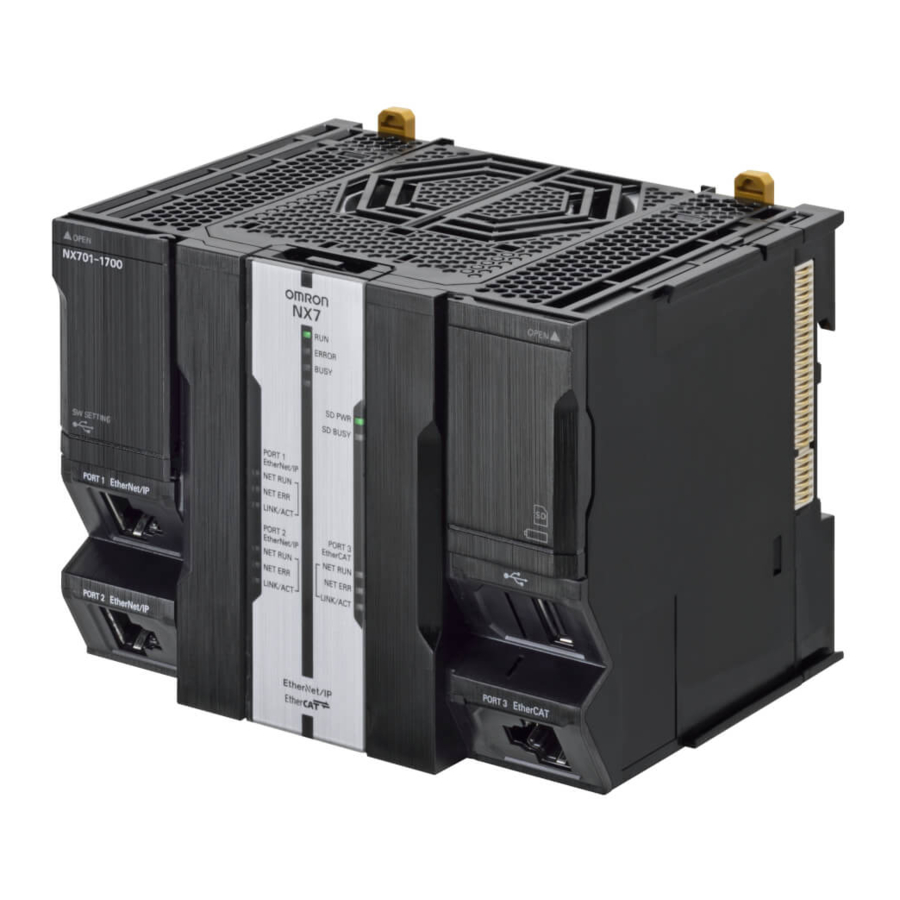
- Page 79 3 Configuration Units ERROR BUSY Indicators at the top SD PWR SD BUSY PORT1 EtherNet/IP NET RUN NET ERR LINK/ACT Indicators at the bottom PORT2 PORT3 EtherNet/IP EtherCAT NET RUN NET RUN NET ERR NET ERR LINK/ACT LINK/ACT Indicators at the Top ERROR BUSY SD PWR...
- Page 80 3 Configuration Units Indicator Color Status Meaning ERROR Lit. Self-diagnosis found one of the following errors. • Controller error in the major fault level • CPU error Flashing at 1- Self-diagnosis found one of the following errors. • s intervals. Controller error in the partial fault level (an error in which all control of a Function Module is disabled) •...
- Page 81 3 Configuration Units Indicators at the Bottom PORT1 EtherNet/IP NET RUN NET ERR LINK/ACT Built-in PORT2 PORT3 EtherNet/IP port EtherNet/IP EtherCAT indicators NET RUN NET RUN Built-in NET ERR NET ERR EtherCAT port indicators LINK/ACT LINK/ACT These indicators show the operation status of the built-in ports of the CPU Unit. Port 1 and port 2 are the indicators for the built-in EtherNet/IP ports, while port 3 is the indicators for the built-in EtherCAT port.
-
Page 82: Sd Memory Cards
3 Configuration Units Indicator Color Status Meaning Green Lit. EtherCAT communications are in progress. • Inputs and outputs for I/O data are in operation. Flashing EtherCAT communications are established. This indicator shows either of the following conditions. • Only message communications are in operation. •... -
Page 83: Purpose
Shows the lot number and the serial number of the CPU Unit. number DDMYY: Lot number, £: For use by OMRON, xxxx: Serial number M is 1 to 9 for January to September, X for October, Y for November, and Z for December. -
Page 84: Power Supply Units
3 Configuration Units SD Memory Cards This section describes the models, specifications, and application of the SD Memory Cards. 3-2-1 Models and Specifications Refer to Specifications of Supported SD Memory Cards, Folders, and Files in the NJ/NX-series CPU Unit Software User’s Manual (Cat. No. W501)for details. 3-2-2 Purpose You can use the SD Memory Card for the following applications. -
Page 85: Part Names And Functions
3 Configuration Units Power Supply Units This section describes the models and specifications of the Power Supply Units as well as the names and functions of the parts. 3-3-1 Models and Specifications NX7-series Power Supply Units Use an NX7-series Power Supply Unit to supply power to an NX7-series CPU Unit. Item Specification Model... - Page 86 3 Configuration Units Apply the voltage between the Power Supply Unit’s L1 or L2 terminal and the GR terminal when testing in- sulation and dielectric strength. The tests can also be performed with the LG terminal and GR terminal connected to each other. In this case, the leakage current will be 10 mA or less.
- Page 87 3 Configuration Units Letter Name Function Dropout prevention lock release Releases the dropout prevention lock. lever DIN Track mounting hooks These hooks are used to mount the Unit to a DIN Track. Sliders Holds the Units together. PWR indicator Indicates that the power supply is operating. Connector Connects to the CPU Unit.
-
Page 88: Sysmac Studio
3 Configuration Units Status Operation The CPU Unit is starting (until entering the operating status that is specified in the Startup Mode setting). Operation stopped (PROGRAM mode). Controller error in the major fault level occurred. 3-14 NX-series CPU Unit Hardware User’s Manual (W535) - Page 89 3 Configuration Units Sysmac Studio The Sysmac Studio is a Support Software package that provides an integrated development environ- ment to design, program, debug, and maintain SYSMAC NJ/NX-series Controllers. This section describes the models and connecting methods of the Sysmac Studio. 3-4-1 Model Numbers The model numbers of the Sysmac Studio Standard Edition are given in the following table.
- Page 90 3 Configuration Units • Directly specify the IP address of the remote device. A direct connection is made from the Sysmac Studio. The IP address and connection device do not need to be specified. • You can make the connection whether or not a switching hub is used.
-
Page 91: Installation And Wiring
Installation and Wiring This section describes how to install and wire the NX-series NX701 CPU Unit as well as details on installation locations. Processing at Power ON and Power OFF ............ 4-2 4-1-1 Power ON Operation ..................4-2 4-1-2 Power OFF Operation ..................4-3 4-1-3 Resetting the Controller from the Sysmac Studio ........... -
Page 92: Processing At Power On And Power Off
4 Installation and Wiring Processing at Power ON and Power WARNING • Do not touch the terminal section while power is ON. Electrical shock may occur. • Do not disassemble any of the Units. Particularly the Power Supply Units contain parts with high voltages when power is ON or immediately after power is turned OFF. -
Page 93: Power Off Operation
4 Installation and Wiring Operating Mode at Startup The system will immediately enter RUN mode if RUN mode (default) is set as the startup operating mode. The system will immediately enter PROGRAM mode if PROGRAM mode is set as the startup operating mode. - Page 94 4 Installation and Wiring Operation at Power OFF Operation Execution of the user program is ended if a power interruption exceeds the time shown in the table below. The processing after power interruption confirmation (described below) is performed, and then the system (i.e., CPU Unit) stops.
-
Page 95: Resetting The Controller From The Sysmac Studio
4 Installation and Wiring Momentary power interruption time from voltage drop until recovery Voltage drop Voltage recovery AC: 85 V max. DC: 20.4 V max. The CPU Unit will not interrupt Executing user program execution of user program Power OFF detection time AC: 30.5 to 45.5 ms DC: 5.0 to 20.5 ms Processing After Power Interruption Is Confirmed... -
Page 96: Fail-Safe Circuits
4 Installation and Wiring Fail-safe Circuits WARNING Provide safety measures in external circuits to ensure safety in the system if an ab- normality occurs due to malfunction of the CPU Unit, other Units, or slaves or due to other external factors affecting operation. Not doing so may result in serious accidents due to incorrect operation. -
Page 97: Order Of Powering Up The Controller And Controlled System
4 Installation and Wiring Precautions for Safe Use It takes approximately 10 to 20 seconds to enter RUN mode after the power supply is turned ON. During that time, outputs will be OFF or the values will be according to settings in the Units or slaves. - Page 98 4 Installation and Wiring Interlock circuit ON_MC1 Motor clockwise Controller ON_MC2 Motor counterclockwise This circuit prevents outputs MC1 and MC2 from both being ON at the same time even if both Control- ler outputs ON_MC1 and ON_MC2 are ON due to a malfunction. NX-series CPU Unit Hardware User’s Manual (W535)
-
Page 99: Mounting Units
4 Installation and Wiring Mounting Units This section describes how to mount Units to the NX-series Controller. In this description, the combination of the NX-series CPU Unit and the NX-series Power Supply Unit is called a CPU Module. Precautions for Safe Use •... -
Page 100: Installation In A Control Panel
4 Installation and Wiring • Do not install the Controller directly above equipment that generates a large amount of heat such as heaters, transformers, or high-capacity resistors. • If the ambient temperature exceeds 55°C, install a cooling fan or air conditioner. Control panel NX-series... - Page 101 4 Installation and Wiring Mounting with the DIN Track on the Bottom Mounting with the DIN Track on the Top DIN Track DIN Track Mounting with the DIN Track Installed Vertically Mounting with the Rack Upside down Installation Method in Control Panels An NX-series Controller must be mounted inside a control panel on DIN Track.
- Page 102 4 Installation and Wiring Duct 20 mm min. DIN Track Unit 20 mm min. Duct Additional Information If you want to attach or remove the Fan Unit of CPU Unit while the CPU Rack remains mounted on the control panel, ensure at least 50 mm between the tops of CPU Unit and the wiring duct. Duct 50 mm min.
- Page 103 Preparations for Installation We recommend using the following products to install the Unit on a DIN Track. Name Model Manufacturer Remarks • 35-mm DIN Track PFP-50N OMRON Corporation Length: 50 cm • Material: Aluminum • Surface treatment: Insulated • PFP-100N OMRON Corporation Length: 100 cm •...
-
Page 104: Preparations For Installation
4 Installation and Wiring Not all of the combinations of the DIN Tracks and End Plates listed above are possible. Confirm applicability of the combinations in the following table. DIN Track model PFP-M (OMRON) CLIPFIX 35 (Phoenix Contact) PFP-50N Possible. - Page 105 4 Installation and Wiring CLIPFIX 35 (Two) 4-3-3 Installing the CPU Module This section describes how to install the CPU Module. Precautions for Safe Use • Do not apply labels or tape to the Unit. When the Unit is installed or removed, adhesive or scraps may adhere to the pins in the NX bus connector, which may result in malfunctions.
-
Page 106: Installing The Cpu Module
4 Installation and Wiring Precautions for Correct Use • When you install the Unit, be careful not to touch or bump the pins in the NX bus connector. • When you handle the Unit, be careful not to apply stress to the pins in the NX bus connector. If the Unit is installed and the power supply is turned ON when the pins in the NX bus con- nector are deformed, contact failure may cause malfunctions. - Page 107 4 Installation and Wiring Make sure that the DIN Track mounting hooks on each Unit of the CPU Module are in the un- locked position. DIN Track mounting hooks 9.5 mm 4.5 mm DIN Track Mounting DIN Track Mounting Hooks in Locked Position Hooks in Unlocked Position If the DIN Track mounting hooks are pulled up, they are in the unlocked position.
- Page 108 4 Installation and Wiring 2) Press the DIN Track mounting hooks down to the locked position. After mounting, check to be sure that the CPU Module and the End Cover securely mount- ed on the DIN Track. 4-3-4 Mounting the End Cover Use the following procedure to mount the End Cover if you removed it when mounting the Unit or if it is displaced from the CPU Unit.
- Page 109 After you mount the Unit on the DIN Track, always secure it with End Plates at both sides. If you do not secure it, the Unit may be damaged or malfunction. Using PFP-M (OMRON) To mount an End Plate, 1) hook the bottom of it on the bottom of the DIN Track and 2) rotate the End Plate to hook the top of it on the top of the DIN Track.
-
Page 110: Mounting The End Cover
4 Installation and Wiring To remove an End Plate 1) insert the tip of a flat-blade screwdriver into groove “a” and 2) use “b” as a fulcrum and lift the end of the screwdriver, as shown in the following diagram. Flat-blade screwdriver 4-3-6 Installing and Removing the SD Memory Card... -
Page 111: Mounting The End Plates
• The service life may be extremely short if a non-OMRON SD Memory Card is used. Also, operation may be affected due to deterioration in writing performance. • If you use an OMRON SD Memory Card, the end of the life of the SD Memory Card can be detected in the following ways. - Page 112 4 Installation and Wiring Removing the SD Memory Card Press the SD Memory Card power supply switch. S D P W R SD Memory Card power supply switch Press the SD Memory Card after the SD BUSY indicator is no longer lit. SD Memory Card The SD Memory Card will be ejected from the compartment.
-
Page 113: Installing And Removing The Sd Memory Card
4 Installation and Wiring Pull out the SD Memory Card. Close the CPU Unit cover when an SD Memory Card is not being used. 4-3-7 Removing the CPU Module This section describes how to remove the CPU Module. 4-23 NX-series CPU Unit Hardware User’s Manual (W535) - Page 114 4 Installation and Wiring Precautions for Safe Use • Do not apply labels or tape to the Unit. When the Unit is installed or removed, adhesive or scraps may adhere to the pins in the NX bus connector, which may result in malfunctions. •...
- Page 115 4 Installation and Wiring Remove the CPU Module from the DIN Track. 1) Press the dropout prevention lock release lever on the front left side of the Power Supply Unit to release the dropout prevention lock. 2) Press and hold the release lever, pull the CPU Module straight forward to remove it. 4-25 NX-series CPU Unit Hardware User’s Manual (W535)
- Page 116 4 Installation and Wiring 4-3-8 Assembled Appearance and Dimensions Installation Dimensions End Cover Power Supply Unit End Plate 1.35 CPU Unit End Plate DIN Track 32.5 104.5 32.5 94.2 W+(C)+(C) Unit: [mm] Unit: [mm] W: Total width of the Power Supply Unit and CPU Unit (the End Cover is included in the CPU Unit width) •...
-
Page 117: Removing The Cpu Module
4 Installation and Wiring Installation Height With a height of 100 mm, the CPU Unit is the highest component in an NX-series CPU Rack. When a cable is connected (such as a Unit communications cable), however, even greater height is required. Allow sufficient depth in the control panel containing the Controller. - Page 118 4 Installation and Wiring Wiring WARNING • Do not input a voltage or current that exceeds the specified range into a Unit or slave. If a voltage or current that is outside the specified range is input, the Unit or slave may fail or a fire may occur.
-
Page 119: Assembled Appearance And Dimensions
4 Installation and Wiring AC Power Supply • Supply 100 to 240 VAC. • Use the Power Supply Unit of the voltage and frequency shown in the table below. Model Power supply voltage NX-PA9001 100 to 240 VAC 50/60 Hz (85 to 264 VAC, 47 to 63 Hz) •... - Page 120 4 Installation and Wiring DC Power Supplies Precautions When Using A Non-isolated Power Supply Unit NX-PD7001 CAUTION When you connect a computer or other peripheral device to a Controller that has a non-isolated DC Power Supply Unit NX-PD7001, either ground the 0-V side of the external power supply or do not ground it at all.
-
Page 121: Wiring
ON. Refer to 3-1-1 Models and Specifications on page 3-2 for inrush current specifications. We recommend that you use the OMRON S8JX-series or S8VS-series Power Supplies, all of which have the capacity of 180 W or greater. - Page 122 4 Installation and Wiring PA9001 LG (Noise-filter neutral terminal) AC100-2 INPUT L2/N L2/N GR (Ground terminal) OUTPUT AC240V DC24V Terminal Grounding Symbol Function name type Functional Functional grounding is done to protect device and system func- Grounding tions, including prevention of noise from external sources, or pre- vention of noise from devices or equipment that could have harmful effects on other devices or equipment.
- Page 123 4 Installation and Wiring Additional Information The CPU Unit has no ground terminals, thus no DIN Track Contact Plates. Therefore, the grounding part of the CPU Unit will be grounded through the Power Supply Unit. Grounding the CPU Rack This section describes how to ground the ground terminals on the CPU Rack. The protective ground terminals on the Power Supply Units, the functional ground terminals that are provided on some Units, and the DIN Track are grounded.
- Page 124 If the ground wire for a Unit with a ground terminal is shared with power equipment, noise will adverse- ly affect the Units. You can use OMRON NX-AUX01 DIN Track Insulation Spacers with PFP-50N or PFP-100N DIN Tracks to isolate the CPU Rack from the control panel.
-
Page 125: Grounding
Screws, M4 DIN Track Control panel • DIN Track Insulation Spacers NX-AUX01 (OMRON Corporation) Three Spacers are included in one model. 14.8 Precautions for Correct Use If you use DIN Track Insulation Spacers to install a CPU Rack, the height will be increased by approximately 10 mm. - Page 126 4 Installation and Wiring Control Panel Installation To ensure system reliability and safety, the system must be designed and configured according to the installation environment (temperature, humidity, vibration, shock, corrosive gases, overcurrent, noise, etc.). 4-5-1 Temperature Panels have been reduced in size due to space-saving and miniaturization in devices and systems, and the temperature inside the panel may be at least 10 to 15°C higher than outside the panel.
- Page 127 4 Installation and Wiring Forced Ventilation (by Fan at Top of Panel) Controller Controller Air filter Forced Ventilation Method Forced Air Circulation (by Fan in Closed Panel) Controller Controller Forced Air Circulation Room Cooling (Cooling the Entire Room Where the Control Panel Is Lo- cated) Cooler Control panel...
- Page 128 4 Installation and Wiring Control panel Moisture absorber Controller Power ON Heater Examples of Measures against Condensation 4-5-3 Vibration and Shock The Controller is tested for conformity with the sine wave vibration test method (IEC 60068-2-6) and the shock test method (IEC 60068-2-27) of the Environmental Testing for Electrotechnical Products. It is designed so that malfunctioning will not occur within the specifications for vibration and shock.
-
Page 129: Wiring The Built-In Ethercat Port
4 Installation and Wiring Example of Recommended Equipment Arrangement Controller Control panel Control panel High-voltage power panel Example of Poor Equipment Arrangement Controller Control panel Control panel High-voltage power panel Examples of Equipment Arrangement in Panel with High-voltage Devices Arrangement of Controller and Units The coils and contacts in electromagnetic contacts and relays in an external circuit are sources of noise. -
Page 130: Control Panel Installation
4 Installation and Wiring • Use an isolating transformer to significantly reduce noise between the Controller and the ground. In- stall the isolating transformer between the Controller power supply and the noise filter, and do not ground the secondary coil of the transformer. •... - Page 131 4 Installation and Wiring • If the signal lines and power lines cannot be routed in separate ducts, use shielded cable. Connect the shield to the ground terminal at the Controller, and leave it unconnected at the input device. • Wire the lines so that common impedance does not occur. Such wiring will increase the number of wires, so use common return circuits.
-
Page 132: Humidity
4 Installation and Wiring Partition Power Signal Signal Signal supply cables cables cables cables (group A) (group B) (group C) Signal cables Signal cables Signal cables Power supply cables Power supply cables Partitioning Methods for Signal and Power Supply Cables •... -
Page 133: Electrical Environment
4 Installation and Wiring High-voltage power panel Metal tubing Power lines Power lines 200 mm Controller Controller Ground to 100 Ω or less 200 mm Example: Separating Controller from Power Lines Other Precautions • Basic I/O Units have both plus and minus commons, so pay attention to the polarity when wiring. 4-5-6 Grounding This section describes the earthing methods and precautions. - Page 134 4 Installation and Wiring Additional Information • In a country or region where the earthing method is regulated, you must comply with the reg- ulations. Refer to the applicable local and national ordinances of the place where you install the system, or other international laws and regulations. •...
- Page 135 4 Installation and Wiring Each earth electrode must be ground to 100 Ω or less. Connect the ground lines of the device that is connected with a communications cable and oth- er devices as a bundle to a single earth electrode. Be sure that the earth electrode is separated by a minimum of 10 m from any other earth electrode of a device that could be a noise source.
- Page 136 4 Installation and Wiring Precautions for Grounding • To prevent electrical shock, do not connect devices to ground poles (or steel frames) with non- equalized potential to which multiple devices are connected. • Use a ground pole as close to the Controller as possible and keep the ground line as short as possi- ble.
-
Page 137: Grounding
Troubleshooting This section describes the overview of the methods for checking errors. Overview of Troubleshooting................ 5-2 NX-series CPU Unit Hardware User’s Manual (W535) - Page 138 5 Troubleshooting Overview of Troubleshooting You manage all of the errors that occur on the NJ/NX-series Controller as events. This allows you to see what errors have occurred and find corrections for them with the same methods for the entire range of errors that is managed (i.e., CPU Unit, NX Units, NX-series Slave Terminals, EtherCAT slaves, and CJ-series Units).
- Page 139 Inspection and Maintenance This section describes the required inspections and maintenance for the NX-series NX701 CPU Unit. It also describes the service lives and replacement procedures for the Battery and Power Supply Units. Cleaning and Maintenance ................6-2 6-1-1 Cleaning ......................6-2 6-1-2 Periodic Inspections ..................
- Page 140 6 Inspection and Maintenance Cleaning and Maintenance This section describes daily maintenance and the cleaning and inspection methods. Inspect the NX-series CPU Unit daily or periodically in order to keep it in optimal operating condition. 6-1-1 Cleaning Perform the following cleaning procedures periodically to ensure the NX-series CPU Unit is main- tained in the best operating condition.
-
Page 141: Troubleshooting
6 Inspection and Maintenance Periodic Inspection Items Inspec- Inspection details Criteria Correction tion item External Check for voltage fluctua- The voltage Use a voltage tester to check the power power tions at the power supply ter- must be within supply at the terminals. Take necessary supply minals. -
Page 142: Overview Of Troubleshooting
6 Inspection and Maintenance Inspec- Inspection details Criteria Correction tion item Installa- Check that each Unit is con- No looseness Press the connectors together completely tion and nected and locked to the and lock them with the sliders. wiring next Unit securely. Check that cable connectors No looseness Correct any improperly installed connec-... -
Page 143: Inspection And Maintenance
6 Inspection and Maintenance • For poor contact, take a clean cotton cloth, soak the cloth in industrial alcohol, and carefully wipe the contacts clean. Be sure to remove any lint prior to remounting the Unit. Precautions for Correct Use •... -
Page 144: Cleaning And Maintenance
6 Inspection and Maintenance Replacing the Battery The Battery in the NX-series CPU Unit must be replaced periodically as preventative maintenance. (The Battery is a backup power supply for the CPU Unit’s internal clock and the variables that are re- tained during power interruptions.) This section describes how to replace the Battery. - Page 145 6 Inspection and Maintenance Ambient temperature 25 C 40 C 55 C Power ON time rate [%] Battery service life (minimum lifetime) [month] Power ON time Unit model number rate 25°C 40°C 55°C NX701-££££ 100% Additional Information The Battery installed at the time of purchase is only for monitoring purpose to test the battery backup function.
- Page 146 6 Inspection and Maintenance Once a low-battery error has been detected, it will take 5 days (at an ambient temperature of 25°C) before the battery fails if power has been supplied at least once a day. Clock data and variables that are retained during power interruptions can be retained by ensuring that the CPU Unit power is not turned OFF until the Battery has been replaced.
-
Page 147: Unit Replacement Precautions
6 Inspection and Maintenance Additional Information UL standards require that batteries be replaced by experienced technicians. Always place an experienced technician in charge of battery replacement. Turn OFF the power supply to the Controller. If the CPU Unit has not been ON, turn it ON for at least five minutes and then turn it OFF. Additional Information If power is not turned ON for at least five minutes before replacing the battery, the capacitor that backs up memory when the Battery is removed will not be fully charged and memory may be... -
Page 148: Replacing The Battery
6 Inspection and Maintenance Protrusion for placing wires Precautions for Safe Use • Before you replace the Battery, you must first supply power to the Controller for at least 5 mi- nutes, and then you must complete this procedure within 5 minutes at 25°C after turning OFF the power to the CPU Unit to ensure memory backup. - Page 149 6 Inspection and Maintenance Power turned ON Type of data Battery No Battery User program Values before power interruption will be retained by the built-in non-volatile Controller Configurations and Setup memory. Values before Values before power interruption power interruption Event log will be retained.
- Page 150 6 Inspection and Maintenance Replacing the Fan Unit This section describes how to replace the Fan Unit, a part of the NX7-series CPU Unit that allows re- placement as preventive maintenance. 6-3-1 Purpose of Attaching the Fan Unit A CPU that is incorporated in an NX7-series CPU Unit requires forced cooling to maintain its perform- ance.
- Page 151 6 Inspection and Maintenance Additional Information The date of manufacturing can be checked on the side of the Fan Unit. DDMYY gives the lot number, and “M” gives the following meaning. 1 to 9: January to September, X: October, Y: November, Z: December DDMYY 6-3-4 Procedure of Fan Unit Replacement...
-
Page 152: Operation Without A Battery
6 Inspection and Maintenance 2) Use the locating part as a supporting point and push the Fan Unit into the CPU Unit. Make sure that the lever is securely locked and there is no lifting-off of the Fan Unit. The power supply connection for the Fan Unit is established when it is attached to the CPU Unit. -
Page 153: Replacing The Fan Unit
Appendices The appendices provide the general specifications of the NX-series NX701 CPU Unit and Unit dimensions. Specifications ....................A-2 Dimensions ....................A-3 A-2-1 NX-series CPU Units..................A-3 A-2-2 End Cover ....................... A-4 A-2-3 NX-series Power Supply Units ................ A-4 A-2-4 SD Memory Card..................... -
Page 154: Procedure Of Fan Unit Replacement
Listed UL508 and ANSI/ISA 12.12.01 standards Shipbuilding Standards NK, LR Other than the above. Refer to the OMRON website (http://www.ia.omron.com) or consult your OMRON representative for the most recent applicable standards for each model. NX-series CPU Unit Hardware User’s Manual (W535) - Page 155 Appendices A-2 Dimensions Dimensions of the CPU Units are shown as follows. The unit of dimension is millimeter. A-2-1 NX-series CPU Units NX701-££££ ERROR BUSY SHTDWN SD PWR SD BUSY PORT1 EtherNet/IP NET RUN NET ERR LINK/ACT PORT1 EtherNet/IP PORT2 PORT3 EtherNet/IP EtherCAT...
- Page 156 Appendices A-2-2 End Cover A-2-3 NX-series Power Supply Units NX-PA9001 NX-series CPU Unit Hardware User’s Manual (W535)
-
Page 157: Appendices
Appendices NX-PD7001 A-2-4 SD Memory Card 32±0.1 2.1±0.15 24±0.1 NX-series CPU Unit Hardware User’s Manual (W535) -
Page 158: A-1 Specifications
Appendices A-3 Version Information Refer to Version Information for NX-series Controllers in the NJ/NX-series CPU Unit Software User’s Manual (Cat. No. W501) for the relationship between the unit versions of NX-series CPU Unit and the Sysmac Studio versions, and for the functions that are supported by each unit version. A-3-1 Relationship between Hardware Revisions of CPU Units and Sysmac Studio Versions... -
Page 159: A-2 Dimensions
Index NX-series CPU Unit Hardware User’s Manual (W535) -
Page 160: A-2-2 End Cover
Index Index Grounding...............4-31, 4-43 Applicable standards............A-2 ID Information Indication..........3-3, 3-9 Indicators................3-4 Basic System Configuration........1-4, 2-2 Inrush current..............3-11 Battery............3-2, 3-8, 6-8, A-2 Installation Dimensions............4-26 Battery connector.............. 3-3 Installation Height............4-27 Installation in Cabinets or Control Panels......4-9 Battery Replacement Procedure........6-8 Battery Service Life and Replacement Period....6-6 Installation Method in Control Panels...... -
Page 161: A-2-4 Sd Memory Card
Index Restricted region............ 4-15, 4-24 RUN...................3-5 RUN Output..........3-11, 3-13, 4-29, 4-31 Safe Mode................. 3-4 SD BUSY................3-6 SD Memory Card............2-4, 4-20 SD Memory Card connector..........3-3 SD Memory Card power supply switch......3-3 SD PWR................3-6 Slider..............3-13, 4-16 Star earthing............4-43, 4-44 Startup................ -
Page 162: A-3 Version Information
Index NX-series CPU Unit Hardware User’s Manual (W535) -
Page 164: Functions That Were Added Or Changed For Each Unit Version
The Netherlands Hoffman Estates, IL 60169 U.S.A. Tel: (31)2356-81-300/Fax: (31)2356-81-388 Tel: (1) 847-843-7900/Fax: (1) 847-843-7787 © OMRON Corporation 2015-2022 All Rights Reserved. OMRON (CHINA) CO., LTD. OMRON ASIA PACIFIC PTE. LTD. In the interest of product improvement, Room 2211, Bank of China Tower, 438B Alexandra Road, #08-01/02 Alexandra specifications are subject to change without notice.