Table of Contents
Advertisement
Applications
The networked TEC3000 Series Thermostat Controllers
are stand-alone and field-selectable BACnet
N2 networked devices. Wireless networked models of the
TEC3000 Series Thermostat Controller are also available.
Proportional Fan Coil and Individual Zone Thermostat
Controllers provide control of the following:
• Local hydronic reheat valves
• Pressure-dependent variable air volume (VAV)
equipment with or without local reheat
• Two- or four-pipe fan coils
• Cabinet unit heaters
• Other individual zone equipment using an on/off or
floating control input
The networked models feature a field-selectable
Building Automation System (BAS) BACnet MS/TP or N2
communication capability that enables remote monitoring
and programming for efficient space temperature control.
The wireless models (TEC30xx-xx-000) are compatible
only with the WNC1800/ZFR182x Pro Series Wireless Field
Bus System that enables communication with a building
automation system (BAS). The new wireless models
(TEC31xx-14-000) are compatible only with WRG1830/
ZFR183x Pro Series Wireless Field Bus System. All models
include a USB port configuration that reduces installation
time to allow simple backup and restore features from a
USB drive, which enables rapid cloning of configuration
between similar units.
Some models have occupancy sensing capability built into
the device. These thermostat controllers maximize up to
30% energy savings in high-energy usage commercial
buildings, such as schools and hotels, during occupied
times by using additional standby setpoints.
All models feature an intuitive onboard touchscreen UI
with backlit display that makes setup and operation quick
and easy. For Single-or Two-Stage Economizer Thermostat
Controller models, only the single-speed fan configuration
is supported. For TEC3x1x and TEC3x2x models, multiple
fan configurations are supported for fan coil equipment
types, as follows:
• Single-speed
• Multi-speed (two or three discrete speeds)
• Variable-speed/EC motors (0 to 10 VDC control)
Some models support dehumidification on two-pipe
fan coil units with reheat, and four-pipe fan coil units
with or without reheat. When no heating is required,
the thermostat controller monitors space humidity and
activates dehumidification control as necessary. Heat
and/or reheat is used as required to maintain the space
temperature. For optimal dehumidification performance,
use a fan coil unit that has a multi-speed or variable-speed
fan (VSF).
TEC3000 Series Proportional Fan Coil
Thermostats Installation Guide
Important: The TEC3000 Series Thermostat
Controller is intended to provide an input to
equipment under normal operating conditions.
MS/TP or
Where failure or malfunction of the thermostat
®
controller could lead to personal injury or property
damage to the controlled equipment or other
property, additional precautions must be designed
into the control system. Incorporate and maintain
other devices, such as supervisory or alarm systems
or safety or limit controls, intended to warn of
or protect against failure or malfunction of the
thermostat controller.
Important: Le TEC3000 Series Thermostat Controller
est destiné à transmettre des données entrantes
à un équipement dans des conditions normales
de fonctionnement. Lorsqu'une défaillance ou un
dysfonctionnement du thermostat controller risque
de provoquer des blessures ou d'endommager
l'équipement contrôlé ou un autre équipement, la
conception du système de contrôle doit intégrer des
dispositifs de protection supplémentaires.Veiller
dans ce cas à intégrer de façon permanente d'autres
dispositifs, tels que des systèmes de supervision
ou d'alarme, ou des dispositifs de sécurité ou de
limitation, ayant une fonction d'avertissement
ou de protection en cas de défaillance ou de
dysfonctionnement du thermostat controller.
North American emissions
compliance
United States
This equipment has been tested and found to comply with
the limits for a Class B digital device, pursuant to Part 15
of the FCC Rules. These limits are designed to provide
reasonable protection against harmful interference in
a residential installation. This equipment generates,
uses and can radiate radio frequency energy and, if not
installed and used in accordance with the instructions,
may cause harmful interference to radio communications.
However, there is no guarantee that interference will not
occur in a particular installation. If this equipment does
cause harmful interference to radio or television reception,
which can be determined by turning the equipment
off and on, the user is encouraged to try to correct the
interference by one or more of the following measures:
• Reorient or relocate the receiving antenna.
• Increase the separation between the equipment and
receiver.
• Connect the equipment into an outlet on a circuit
different from that to which the receiver is connected.
• Consult the dealer or an experienced radio/TV
technician for help.
TEC3322-1x-xxx, TEC3323-1x-xxx, TEC3622-1x-xxx,
TEC3623-1x-xxx, TEC3022-1x-xxx, TEC3023-1x-xxx,
LIT-12013162
2020-12-15
TEC312x-14-xxx
Advertisement
Table of Contents

Related Manuals for Johnson Controls TEC3023-14-000


Summary of Contents for Johnson Controls TEC3023-14-000
- Page 1 TEC3000 Series Proportional Fan Coil Thermostats Installation Guide LIT-12013162 2020-12-15 Applications Important: The TEC3000 Series Thermostat Controller is intended to provide an input to The networked TEC3000 Series Thermostat Controllers equipment under normal operating conditions. are stand-alone and field-selectable BACnet MS/TP or Where failure or malfunction of the thermostat ®...
-
Page 2: Installation
Canada For wireless models, the effective transmission range and distance for indoor applications vary because of wireless This Class (B) digital apparatus meets all the requirements signal absorption and reflection due to metal obstructions, of the Canadian Interference-Causing Equipment walls or floors, and furniture that is found in building Regulations. -
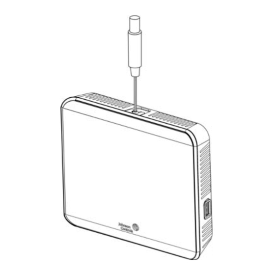
Page 3: Installing The Thermostat Controller
Figure 1: Thermostat controller shown without Figure 2: Removing the security screw from the thermostat occupancy sensor, dimensions, in. (mm) controller cover, shown without occupancy sensor, and removing the thermostat controller cover Align the thermostat controller mounting base on the wall with the security screw on the top and use the base as a template to mark the two mounting hole locations. - Page 4 Figure 4: Hanging the thermostat controller front cover CAUTION Risk of Property Damage Do not apply power to the system before checking all wiring connections. Short circuited or improperly connected wires may result in permanent damage to the equipment. ATTENTION Risque de dégâts matériels Ne pas mettre le système sous tension avant d'avoir vérifié...
- Page 5 devices on the FC Bus and N2 Bus, set the EOL Table 4: TEC3000 model names and code numbers switch to the ON position. See Figure 5. Name Code Name Code number number Figure 5: EOL switch position (left) and installing the thermostat controller cover (right) TEC3023-14 TEC3330-16...
-
Page 6: Terminal Identification
Terminal identification Table 5: Terminal identification Terminal label Function TEC3022, TEC3023, TEC3322, TEC3323, Proportional FC/ TEC3622, TEC3623 TEC312x Proportional FC/ Proportional FC/VAV 24 V 24 VAC hot from transformer FAN H Fan high FAN M Fan medium FAN L Fan low and fan on Auxiliary binary output Auxiliary power input 24 VAC common from transformer... -
Page 7: Wiring Diagrams
Wiring diagrams See Table 5 for terminal identification. Figure 7: Proportional wiring diagram TEC3000 Series Proportional Fan Coil Thermostats Installation Guide... -
Page 8: Setup And Adjustments
Figure 8: Proportional 0 to 10 VDC control (pressure- Figure 13: Proportional 0 to 10 VDC control (two-pipe dependent VAV) and four-pipe fan coil applications) Figure 14: AUX contact wiring Figure 9: Proportional 0 to 10 VDC control (pressure- dependent VAV with changeover sensor/switch) Figure 15: Binary input wiring Figure 10: Proportional 0 to 10 VDC control (pressure- dependent VAV with changeover sensor/switch and... -
Page 9: Customizing The Home Screen
To switch between the modern, classic, light, and Set the passcode on the thermostat controller to dark themes, complete the following steps: prevent the occupants from changing settings that they should not have access to change. Press the Menu icon. Press Settings. -
Page 10: Touchscreen Icons
Touchscreen icons The following table describes the touchscreen icons on the home screen. Press and release a touchscreen icon to activate the TEC. Additional touchscreen icons appear based on the menu, and those icons are also described in the table. Table 6: Touchscreen icons Icon Icon name... - Page 11 Table 6: Touchscreen icons Icon Icon name Description Cooling Hold Indicates that cooling hold mode is enabled. To disable Hold mode, press the button. Heating Hold Indicates that heating hold mode is enabled. To disable Hold mode, press the button. Cooling Setpoint Displays the current cooling setpoint.
-
Page 12: User Lockout
Table 6: Touchscreen icons Icon Icon name Description Occupancy Status Adjusts the occupancy between Unoccupied, Occupied, Temporarily Occupied, Standby, Occupancy Override, Unoccupancy Override. Unoccupied Occupied Temporarily Occupied Standby Override - Occupied Override - Unnoccupied Back Moves the display to the previous screen. Forward Moves the display to the next screen. - Page 13 Using the USB port example, TEC3xx1-00_2018-07-01T1. The files are saved locally and on the USB drive’s root Use the USB port to quickly and easily load firmware directory. See Table 16 if the settings are not upgrades, back up the current settings, and restore backed up correctly.
-
Page 14: Configuring The Thermostat Controller
13. Enter the BACnet MS/TP address through the • Trend keypad. • Status 14. Press Save. • Update 15. After selecting N2 in Step 6, press Save. Installer configuration menu 16. Press the back arrow to return to the previous The thermostat controller comes from the factory with screen. -
Page 15: Setting The Control Mode
Configuring the supply fan - fan coil VDC, whichever value is the lesser, when the fan is turned off. only To configure the variable speed parameters, complete the About this task: following steps: On two-pipe or four-pipe fan coil units, three different Press the Menu icon. -
Page 16: Configuring The Zone Space Or Equipment Size
• Smart—Fan cycles on demand with the controller changeover: automatic changeover using an analog entering cooling or heating modes during unoccupied sensor (thermistor), automatic changeover using a binary periods but is continuously running during occupied switch, or remote changeover from a BAS and manual and standby periods changeover. -
Page 17: Dehumidification Control
Dehumidification control Press Heating Valve Starting Position and use the up and down arrows to set the value for the About this task: The TEC3000 controller supports position the heating valve can open to at the start of dehumidification control on fan coil devices under three dehumidification. -
Page 18: Temperature Setpoints
START-POS, COIL-TPR-TIME, DEHUM-OVRGLG-LIM, and Table 8: Setpoint operation CHWST-SP. Mode of Details Temperature setpoints setpoint operation About this task: Occ Setpoint This is the default mode and the original The thermostat controller provides a flexible setpoint Select = mode of operation that the TEC was configuration to give power to the building owner while Setpoint released with (the next three modes are... -
Page 19: Configuring Occupancy
Configuring occupancy • Temporary occupancy binary input Occupancy is determined using a top-down decision To adapt to nearly any application, the TEC3000 controller matrix as shown in Table 9. supports a wide variety of occupancy sources, such as: Enumerations may not match the TEC3000 Series •... -
Page 20: Setting The Local Schedule
Table 10: BAS objects for scheduling Note: If events are already set for the selected days, they appear in the corresponding event OCC- LOCAL-OCC NET-OCC Occupancy box. If any events conflict between selected CONFIG (Commande schedule days, an asterisk appears in the event box. See d by Figure 18. -
Page 21: Overriding The Occupancy Mode
Enabling optimal start Note: If you do not select Save at this point, the event is not saved and you must repeat the About this task: event selection sequence. The TEC supports an advanced optimal start algorithm. The algorithm works in conjunction with a local schedule Figure 21: Saving the event to pre-heat or pre-cool the zone before scheduled occupancy periods begin, in order to bring the zone... -
Page 22: Configurable Binary Inputs
Inputs are accessed through Setup > Inputs. Both BIs can be configured to support the following options: control. Additionally, the PID features Johnson Controls • Disabled—Sets the binary input to an unused state. proprietary Pattern Recognition Adaptive Control (PRAC When disabled, you can use the binary input for... -
Page 23: Aux Control
Table 12: Input polarities on the controller configuration. To enter commissioning mode, complete the following steps: Contact open Contact closed Press the Menu icon. configuration Press Setup. Service Service Alarm Inactive Service Alarm Select Commissioning. Fan Lock No Airflow Airflow Confirm that the selection was intentional. - Page 24 If the fan type is variable speed or multi speed, you can Do one of the following after the restart based on select the speed at which the fan runs to satisfy the the type of sensor you are configuring: minimum hourly runtime.
-
Page 25: Available Fault Diagnostics
Table 13: Point descriptions and suggested write • Supply Air Temperature Diagnostics—The TEC3000 supports diagnostics when you have a Supply Air interval ranges Temperature installed. The TEC3000 monitors the Name Description Suggested write supply air. If you call for cooling or heating and the interval range temperature does not fall or rise by at least the supply air temperature alarm offset value within the supply... -
Page 26: Menus And Submenus
Menus and submenus In the following table, the * indicates that the menus depend on your configuration. Table 14: Menus and submenus Level 1 Level 2 Level 3 Setpoints Dehumidification Dehumidification Cooling Valve Minimum Position* Cooling Valve Starting Position* Heating Valve Starting Position* Coil Tempering Time* Dehumidification Overcool Limit* Chilled Water Supply Temperature Setpoint*... - Page 27 Table 14: Menus and submenus Level 1 Level 2 Level 3 Display Settings Passcode Enabled Passcode* Brightness Setting Enable Backlight Timeout Units Time Time Zone Set Time Format Date Set Date Format Language Show Fan Button on Home Show Temp on Home Show Humidity on Home Show Off Button on Home Show Hold Button...
- Page 28 Table 14: Menus and submenus Level 1 Level 2 Level 3 Setup General Setup Control Mode Unit Enable Fan Mode* Max Setpoint Offset Fan On Delay* Fan Off Delay* Frost Protection Dehum Enable* Unocc Dehum Enable Dehumidification Sequence Mode* Aux Mode Load Shed Rate Limit Load Shed Adjust Fan Alarm Delay...
- Page 29 Table 14: Menus and submenus Level 1 Level 2 Level 3 Setup (continued) Tuning Setup Temp Control Setup Reset PID Tuning Deadband* Auto Economizer Tuning Heat Prop Band* Heat Integral Time* Heat Process Range* Heat Saturation Time* Heat Time Constant* Heat Process Dead Time* Heat Period* Cool Prop Band*...
- Page 30 Table 14: Menus and submenus Level 1 Level 2 Level 3 Equipment Setup General Unit Type Valve Open Voltage Valve Closed Voltage Unoccupied Off Delay Supply Fan Supply Fan Type* Start Voltage* Full Speed Voltage* Minimum Command* Medium Speed On Cmd* High Speed On Cmd* Reheat Reheat Installed...
- Page 31 Table 14: Menus and submenus Level 1 Level 2 Level 3 Controller Info Model Name Software Version Unit Name Device Name Device Description Commissioning Supply Air Temperature Heat Command Cool Command Supply Fan Update View Version Load Firmware Restore* Backup* For wireless models: Radio Code Version Network Status...
- Page 32 Table 15: TE-6300 Series Temperature Sensors (order separately) Sensor type Mounting style Probe length Product code number Nickel (1k ohm) 8 in. (203 mm) TE-6311A-1 Adjustable Averaging 8 ft (2.4 m) TE-6315M-1 TE-6315V-2 17 ft (5.2 m) TE-6316M-1 TE-6316V-2 Duct 4 in.
-
Page 33: Troubleshooting
Johnson Controls under the RMA program. Internal Sensor Fail An internal sensor has failed on the Order replacement units and return the TEC. affected devices to Johnson Controls under the RMA program. TEC3000 Series Proportional Fan Coil Thermostats Installation Guide... - Page 34 Calibration Corrupt Factory calibration data is lost or is Order replacement units and return the not installed. affected devices to Johnson Controls under the RMA program. Changeover Fail The Supply Temperature Sensor is Follow the same steps as Supply Temp Fail not installed, has failed, or has been alarm.
- Page 35 Controller Fault The controller has detected an Order replacement units and return the internal fault that it cannot recover. affected devices to Johnson Controls under the RMA program. An unknown error has prevented the Order replacement units and return the controller from turning on.
- Page 36 Table 17: Troubleshooting details Symptom Probable causes Solutions The controller displays Idle The two-pipe fan coil/VAV Check the wiring of the supply temperature with a Unit Status of Cooling system does not have a sensor/switch. changeover sensor and switch Unavailable due to Verify that the changeover is set up Changeover despite being above connected, or the sensor/switch...
- Page 37 A hardware failure causes Order replacement units and return the affected the two boards to incorrectly devices to Johnson Controls under the RMA identify themselves. program. The controller displays An internal fault was detected Order replacement units and return the affected Controller Fault.
- Page 38 Table 17: Troubleshooting details Symptom Probable causes Solutions The touchscreen is unresponsive. You tap the display or touch the Reboot the controller. Do not interact with the controller within 5 mm of the controller until the home screen displays. You do not tap the touchscreen, display when power is applied to but the display acts as if it is the controller.
-
Page 39: Repair Information
The performance specifications are nominal and conform to acceptable industry standards. For application at conditions beyond these specifications, consult the local Johnson Controls office. Johnson Controls shall not be liable for damages resulting from misapplication or misuse of its products. -
Page 40: Contact Information
Contact information Contact your local branch office: www.johnsoncontrols.com/locations Contact Johnson Controls: www.johnsoncontrols.com/ contact-us © 2020 Johnson Controls. All rights reserved. All specifications and other information shown were current as of document revision and are subject to change without notice. www.johnsoncontrols.com...