Johnson Controls TEC3000 Series Quick Start Manual
Proportional fan coil thermostats
Hide thumbs
Also See for TEC3000 Series:
- Installation manual (65 pages) ,
- Quick start manual (33 pages) ,
- Installation instructions manual (49 pages)
Table of Contents
Advertisement
Quick Links
North American emissions
compliance
United States
This equipment has been tested and found to comply with
the limits for a Class B digital device, pursuant to Part 15
of the FCC Rules. These limits are designed to provide
reasonable protection against harmful interference in
a residential installation. This equipment generates,
uses and can radiate radio frequency energy and, if not
installed and used in accordance with the instructions,
may cause harmful interference to radio communications.
However, there is no guarantee that interference will not
occur in a particular installation. If this equipment does
cause harmful interference to radio or television reception,
which can be determined by turning the equipment
off and on, the user is encouraged to try to correct the
interference by one or more of the following measures:
• Reorient or relocate the receiving antenna.
• Increase the separation between the equipment and
receiver.
• Connect the equipment into an outlet on a circuit
different from that to which the receiver is connected.
• Consult the dealer or an experienced radio/TV
technician for help.
Canada
This Class (B) digital apparatus meets all the requirements
of the Canadian Interference-Causing Equipment
Regulations.
Cet appareil numérique de la Classe (B) respecte toutes
les exigences du Réglement sur le matériel brouilleur du
Canada.
Installation
Parts included
• One TEC3000 Series Thermostat Controller with integral
mounting base
• One installation instructions sheet
Location considerations
For networked models, locate the TEC3000 Series
Thermostat Controller:
• On a partitioning wall, approximately 5 ft (1.5 m) above
the floor in a location of average temperature, to allow
for vertical air circulation to the TEC
• Away from direct sunlight, radiant heat, outside walls,
outside doors, air discharge grills, stairwells, and from
behind doors
TEC3000 Series Proportional Fan Coil
Thermostats Quick Start Guide
• Away from steam or water pipes, warm air stacks,
unconditioned areas (not heated or cooled), or sources
of electrical interference
• In a clear path between the integrated passive infrared
(PIR) occupancy sensor, if equipped, and the space it
monitors
For wireless models, also locate the thermostat controller:
• Outside of a recessed area, metal enclosure, or shelving
unit
• On the same building level as the other wireless devices
on the same personal area network (PAN)
• At least 2 in. (51 mm) away from any metal obstruction
• In the direct line of sight to other wireless devices on
the same PAN. Signal transmission is best if the path
between the TEC3000 and other wireless devices is
direct as possible. Line of sight is desirable but not
required. See Table 1 and Table 2 for the recommended
and maximum distances.
• Away from metal and large solid obstructions, that
includes equipment rooms and elevator shafts and
concrete or brick walls, between the TEC3000 and
the ZFR182x or ZFR183x Router/Repeater or ZFR Pro
Coordinator Radio
• Within range of two or more wireless devices on the
same PAN. Redundancy in the layout provides the best
reliability in wireless installations
• At least 20 ft (6 m) from a microwave oven
For integrated PIR models, make sure that the thermostat
controller is located centrally, where occupant movement
is frequent. Ensure that the unit is not blocked by a plastic
tamper resistant enclosure, such as the GRD10A-608. The
plastic enclosure blocks the occupancy sensing capability.
The use of insulating foam pads is necessary for
installations where wiring passes through the wall to the
thermostat.
For wireless models, the effective transmission range and
distance for indoor applications vary because of wireless
signal absorption and reflection due to metal obstructions,
walls or floors, and furniture that is found in building
interiors.
Note: Allow for sufficient clearance to insert a USB
drive into the USB port
Important: Only connect memory devices to the USB
port. Do not use it for charging external devices.
Part No. 24-11353-00028 Rev. E
*241135300028E*
(barcode for factory use only)
TEC3322-1x-xxx, TEC3323-1x-xxx, TEC3622-1x-xxx,
TEC3623-1x-xxx, TEC3022-1x-xxx, TEC3023-1x-xxx,
2020-12-15
TEC312x-14-xxx
Advertisement
Table of Contents

Related Manuals for Johnson Controls TEC3000 Series


Summary of Contents for Johnson Controls TEC3000 Series
- Page 1 Parts included signal absorption and reflection due to metal obstructions, walls or floors, and furniture that is found in building • One TEC3000 Series Thermostat Controller with integral interiors. mounting base Note: Allow for sufficient clearance to insert a USB •...
-
Page 2: Installing The Thermostat Controller
Align the thermostat controller mounting base on the wall with the security screw on the top and use the base as a template to mark the two mounting hole locations. See Figure 3. TEC3000 Series Proportional Fan Coil Thermostats Quick Start Guide... - Page 3 TEC3000 Series Thermostat Controller. Important: Use correct ESD precautions during installation and servicing to avoid damage to the electronic circuits of the thermostat controller. To wire the thermostat controller, complete the following steps: TEC3000 Series Proportional Fan Coil Thermostats Quick Start Guide...
- Page 4 - For VAV and two-pipe systems, connect the valve to the heating output. - Only one transformer is required for each TEC. - Power to the AUX contact comes from the reheat coil. TEC3000 Series Proportional Fan Coil Thermostats Quick Start Guide...
-
Page 5: Wiring Diagrams
Wiring diagrams Figure 5: Proportional wiring diagram (See Table 3 for terminal identification) TEC3000 Series Proportional Fan Coil Thermostats Quick Start Guide... -
Page 6: Setup And Adjustments
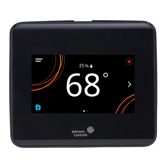
Figure 14: Thermostat controller home screen (shown with light and dark themes) To switch between the modern, classic, light, and dark themes, complete the following steps: Press the Menu icon. Press Settings. TEC3000 Series Proportional Fan Coil Thermostats Quick Start Guide... -
Page 7: Touchscreen Icons
No Signal Set the passcode on the thermostat controller to prevent the occupants from changing settings that they should not have access to change. TEC3000 Series Proportional Fan Coil Thermostats Quick Start Guide... - Page 8 Show Hold button is set to No. Heating Mode Indicates that heating mode is selected. Cooling Mode Indicates that cooling mode is selected. Auto Mode Indicates that Auto mode is selected. TEC3000 Series Proportional Fan Coil Thermostats Quick Start Guide...
-
Page 9: User Lockout
The current screen returns to the home screen and turns off if the current screen is not touched for 3 minutes. Touch the screen to turn it on again. To disable the TEC3000 Series Proportional Fan Coil Thermostats Quick Start Guide... -
Page 10: Setting The Control Mode
When the VSF is configured for reverse acting mode, when the Start Voltage is above Full Speed Voltage, the VSF output is set to 10 VDC or the Start Voltage minus 1 TEC3000 Series Proportional Fan Coil Thermostats Quick Start Guide... -
Page 11: Configuring The Zone Space Or Equipment Size
When in dehumidification mode, the multi-speed or variable- speed fan operates at the appropriate speed to maintain balance between maximizing condensation and moisture removal and keeping the zone from overcooling. TEC3000 Series Proportional Fan Coil Thermostats Quick Start Guide... -
Page 12: Setting The Local Schedule
BAS. The Schedule Source must be selected to tell the fan runtime. When you enabled the Scheduled Circulation controller where to read the occupancy source from. Only When Occupied setting, the fan does not turn on at TEC3000 Series Proportional Fan Coil Thermostats Quick Start Guide... -
Page 13: Menus And Submenus
Min Heating Setpoint* Max Cooling Setpoint* Min Cooling Setpoint* Max Setpoint* Min Setpoint* Scheduling Schedule Options Set Schedule Optimal Start Enable Temp Occ Duration Motion Sensor Timeout Manual Occupancy Mode Schedule Source TEC3000 Series Proportional Fan Coil Thermostats Quick Start Guide... - Page 14 Show Temp on Home Show Humidity on Home Show Off Button on Home Show Hold Button Show Setpoint on Home Show Alarms on Home Show Occ Status Show Unit Status Show Date/Time TEC3000 Series Proportional Fan Coil Thermostats Quick Start Guide...
- Page 15 Zone Temp Sensor Zone Temp Offset Humidity Offset Reset Sensors For networked models: Zone Temp Alarm Enabled For networked models: Zone Temp Low Limit For networked models: Zone Temp High Limit TEC3000 Series Proportional Fan Coil Thermostats Quick Start Guide...
- Page 16 Network Setup FC Comm Mode BACnet Instance ID* For networked models: N2 Address* BACnet Address* For networked models: MSTP Baud Rate* BACnet Encoding Type BACnet/MSTP Communication Mode For wireless models: Pan ID TEC3000 Series Proportional Fan Coil Thermostats Quick Start Guide...
- Page 17 Supply Air Temperature Changeover State Zone Temp Source Control Status Cooling % Command Heating % Command Reheat % Command Cool Stage 1 Heat Stage 1 Reheat Stage 1 Fan % Command TEC3000 Series Proportional Fan Coil Thermostats Quick Start Guide...
-
Page 18: Troubleshooting
Johnson Controls under the RMA program. Internal Sensor Fail An internal sensor has failed on the Order replacement units and return the TEC. affected devices to Johnson Controls under the RMA program. TEC3000 Series Proportional Fan Coil Thermostats Quick Start Guide... - Page 19 BAS to ensure that it is still online and providing the TEC with the humidity reading. If removal of the BAS mapping was intentional, reset sensors through the menu. TEC3000 Series Proportional Fan Coil Thermostats Quick Start Guide...
- Page 20 Limit. Zone Temperature Too Hot The Zone Temperature increased Verify that the TEC and the RTU cooling are above the configured Zone Temp enabled and functioning. High Limit. TEC3000 Series Proportional Fan Coil Thermostats Quick Start Guide...
- Page 21 Try restoring a different backup file. from a backup. The Restore file is from an Ensure that the backup file being restored was incompatible model TEC. from the same model TEC. TEC3000 Series Proportional Fan Coil Thermostats Quick Start Guide...
- Page 22 TEC. Some icons are hidden. Lockout levels are used or the See Table 5 for lockout levels and access details. icons are hidden due to the display settings. TEC3000 Series Proportional Fan Coil Thermostats Quick Start Guide...
- Page 23 Note: For common MS/TP troubleshooting information, refer to the MS/TP Communications Bus Technical Bulletin (LIT-12011034). TEC3000 Series Proportional Fan Coil Thermostats technical specifications Table 10: TEC3000 Series Networked and Wireless Proportional Fan Coil and Individual Zone Thermostat Controllers with Dehumidification Capability Specification Description...
-
Page 24: Repair Information
Your use of this product constitutes an agreement to such terms. Patents Patents: https://jcipat.com © 2020 Johnson Controls. All rights reserved. All specifications and other information shown were current as of document revision and are subject to change without notice. www.johnsoncontrols.com...