Q-See QC40198 User Manual
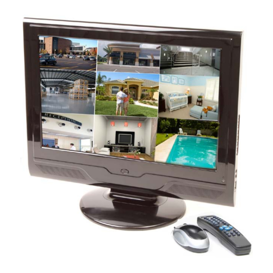
19” lcd observation system
Hide thumbs
Also See for QC40198:
- User manual (141 pages) ,
- User manual (36 pages) ,
- Quick installation manual (10 pages)
Table of Contents
Advertisement
Quick Links
Advertisement
Table of Contents

Related Manuals for Q-See QC40198


Summary of Contents for Q-See QC40198
- Page 1 QC40198 User Manual 19” LCD Observation System Rev 3/30/2010...
- Page 2 CONTACT US Please contact a Q-See support representative first regarding any additional information you need help with regarding product features, specification or assistance with setup. Please contact us using the following methods with questions about your Q-See product. Email: Customer Service cs@dpsi-usa.com...
- Page 3 This combo DVR should be installed in a cool, dry place away from direct sunlight and flammable or explosive substances, etc. 6. Accessories Make sure to only use accessories recommended by Q-See. Before installation, check the package to verify that all the components are included. Contact your local retailer ASAP if something is broken in your package.
-
Page 4: Warranty Information
(3) Damage caused by acts of nature (e.g., earthquake, fire, etc). (4) Equipment damage caused by the maintenance of personnel not authorized by Q-See. (5) Product sold over 12 months ago. - Page 5 Purchase Date Distributor The material in this document is the intellectual property of Q-See. No part of this manual may be reproduced, copied, translated, transmitted, or published in any form or by any means without our company’s expressed written consent.
-
Page 6: Table Of Contents
4.1.2 Main Menu ... 23 4.1.3 Logout ... 24 4.1.4 Auto Resume after Power Failure ... 24 Manual Recording ... 25 4.2.1 Live Viewing ... 25 4.2.2 Manual Record ... 25 ... 1 ... 13 ... 23 QC40198 User Manual... - Page 7 4.9.8 Activate Auto Scan ... 45 4.10 Flip ... 45 UNDERSTANDING OF MENU OPERATIONS AND CONTROLS ... 46 Menu Tree ... 46 Main Menu ... 47 Setting ... 47 5.3.1 General ... 48 5.3.2 Encode ... 49 QC40198 User Manual...
- Page 8 Activate Border Function ... 73 6.3.9 Flip ... 73 WEB OPERATION ... 74 Network Connection ... 74 7.1.1 Port Forwarding ... 74 7.1.2 Pop-Ups and ActiveX Controls ... 75 Login ... 77 7.2.1 Real-time Monitoring ... 79 7.2.2 PTZ ... 81 QC40198 User Manual...
- Page 9 SMARTPHONE ACCESS ... 121 10 TROUBLESHOOTING ... 123 APPENDIX A: HDD CAPACITY CALCULATION ... 128 APPENDIX B: COMPATIBLE USB DRIVE LIST ... 129 APPENDIX C: COMPATIBLE CD/DVD BURNER LIST... 130 APPENDIX D: COMPATIBLE SATA HDD LIST ... 131 QC40198 User Manual...
-
Page 10: Features And Specifications
For a complete list of compatible Smartphone’s, please see Section 9 “Smartphone Access” Internet Explorer, Mozilla Firefox and Google Chrome are registered trademarks of their respective owners and are not affiliated with Q-See. For a complete list of compatible Hard Drives, USB Drives and external DVD Burners, see Appendixes B-D... - Page 11 Standard Ethernet port allows you to access the DVR from a network or the Internet. PTZ camera control Supports PTZ decoder via RS485. Supports a variety of protocols to allow the DVR to control the PTZ speed dome. QC40198 User Manual P a g e...
-
Page 12: Specifications
Channel information, time information and privacy mask zone. Adjust TV output zone suitable to anamorphic video. Cover secret channel with blue screen though system is encoding normally. Screen-lock function to prevent unauthorized user seeing secret video. P a g e QC40198 User Manual 75Ω) P- P, B... - Page 13 When in one-window full-screen playback mode, you can select any zone to activate partial enlargement function. HDD backup Support peripheral USB backup device. (Flash disk, portable disk, etc.) Support USB burner (extension function). Support network download and backup P a g e QC40198 User Manual...
- Page 14 Display version information: channel amount, alarm input and output amount, system version and release date. Display current on-line user Multi-lever user management; various management modes Integrated management for local user, serial port user and network user. Configurable user power. P a g e QC40198 User Manual...
- Page 15 DVR 100-240V-50-60HZ 1.7A (60W) 13W (Excluding HDD) 0℃-+55℃ 10%-90% 86kpa-106kpa 12 x 3 x 16.75 in (300 x80 x425 mm) (with chassis) 11.75 lbs (5.3 Kg) (Excluding HDD) Desktop/wall-mount installation P a g e QC40198 User Manual...
-
Page 16: Controls
Used to adjust playback control bar to go left during playback. 8 Switch the current activated control. Used to adjust the playback control bar to go right during playback. 9 Go back to the previous menu or cancel current selection. Figure 2-1 Function P a g e QC40198 User Manual... -
Page 17: Rear Panel
Figure 2-2 Power button Power input port Alarm input/alarm output/RS485 port Network port USB port RS232 port HDMI port PC input Video CVBS input, audio CVBS input, video CVBS output, audio CVBS output. P a g e QC40198 User Manual... -
Page 18: Remote Control
Backspace: Press for 1.5 seconds to clear all contents in current text box. In HDD information interface, used to switch between HDD record time and other infrmation Special combined operation in some menus. P a g e QC40198 User Manual... - Page 19 In normal playback click this button to pause playback. In pause mode, click this button to resume playback. In real-time monitor mode, click this button to enter video search menu. Various fast speeds and normal playback. 10 | P a g e QC40198 User Manual...
-
Page 20: Mouse Control
When inputting special sign, you can click corresponding numeral in the front panel to input. For example, click numeral 1 you can input “/” , or you can click the numeral in the on-screen keyboard directly. QC40198 User Manual Figure 2-4 11 |... - Page 21 Button Switch the items in the check box. Page up or page down Move Select current control or move control mouse Drag Select motion detection zone mouse Select privacy mask zone. QC40198 User Manual 12 | P a g e...
-
Page 22: Installation And Connection
Open the box to check the accessories and verify that you have received the following items: 1-Combo DVR LCD unit 1-Software CD 1-Ethernet Cable Connection Diagram *Illustrated Connection Suggestion QC40198 User Manual 1-Stand 1-User’s Manual 1-Video/Audio Dongle 13 | P a g e... -
Page 23: Device Installation
INSTALLATION & CONNECTION QC40198 User Manual Device Installation The DVR supports two installation modes: desktop/ wall-mount. The default installation is the desktop type. Refer to Figure 3-1. You will need to purchase the wall mount accessories for wall mount type installation. -
Page 24: Hard Drive Installation
HDD lining up the four Recheck connection of HDD holes of the cover and drive. cables before closing QC40198 User Manual 3. Remove the HDD cover from the rear panel. 7. Place the HDD with the HDD cover back into the slot. -
Page 25: Connecting Power Supply
When hooking your system up to a PC monitor through the BNC video out port you will need to use a composite to VGA converter box. We do not recommend attaching to RCA ports on a TV through the BNC output because it can damage the TV, DVR, or both. QC40198 User Manual Figure 3-2 16 |... -
Page 26: Connecting Audio Input & Output, Bidirectional Audio
Reduce the volume of the sound box. Using more sound-absorbing materials can reduce voice echo and improve acoustics environment Adjust the layout to reduce occurrence of squeaking QC40198 User Manual Figure 3-3 Figure 3-4 17 | P a g e... -
Page 27: Alarm Input And Output Connection
The alarm output port should not be connected to high power load directly (It shall be less than 1A) to avoid high current which may result in relay damage. Please use the co-contactor to establish the connection between the alarm output port and the load. QC40198 User Manual Figure 3-5 Figure 3-6... -
Page 28: Alarm Input And Output Details
You need to close the device power to cancel the alarm. 485 communication port. Used to control devices such as PTZ. Please parallel connect 120Ω between A/B cables if there are too many PTZ cameras 19 | P a g e QC40198 User Manual AB Connection port... -
Page 29: Alarm Input Port
30VDC 2A, 125VAC 1A Maximum switch power 125VA 160W Maximum switch voltage 250VAC, 220VDC Maximum switch currency Between contacts with same 1000VAC 1minute polarity Between contacts with 1000VAC 1minute different polarity 20 | P a g e QC40198 User Manual... -
Page 30: Rs232
3. Please follow the instructions to configure a camera to enable each PTZ device on the combo DVR. Between contacts and 1000VAC 1minute winding Between contacts with same 1500V (10×160us) polarity 3ms max 3ms max Mechanical 50×106 times (3Hz) Electrical 200×103 times (0.5Hz) -40°C ~+70°C (-40°F to +158°F) 21 | P a g e QC40198 User Manual... -
Page 31: Other Interfaces
INSTALLATION & CONNECTION QC40198 User Manual 485 Port Figure 3-9 3.10 Other Interfaces There are other interfaces on the combo DVR, such as USB ports. You can refer to Figure 3-10 for more information. Figure 3-10 22 | P a g e... -
Page 32: Navigation And Controls
After you log in, you will access the system main menu shown in Figure 4-2. There are six icons: search, information, setting, backup, advanced and shutdown. You can move the cursor to highlight an icon, and then double click mouse to enter the sub-menu. QC40198 User Manual Click to switch between numbers, letters... -
Page 33: Logout
DVR. Auto Resume after Power Failure 4.1.4 The system can automatically backup video and resume previous working status after power failure. QC40198 User Manual Figure 4-2 Figure 4-3 Figure 4-4... -
Page 34: Manual Recording
Please check current channel status: “○” means it is not recording, “●” means it is re cording. You can use mouse or direction keys to highlight channel number as illustrated in Figure 4-6. Motion Video loss detection Figure 4-5 Figure 4-6 25 | P a g e QC40198 User Manual Camera lock... - Page 35 4.2.2.5 Click “ALL” next to “Stop” as illustrated in Figure 4-9. System stops all channel recording no matter what mode you have set in the menu (Main menu->Setting- >Schedule) QC40198 User Manual Figure 4-7 Figure 4-8 Figure 4-9 26 |...
-
Page 36: Search & Playback
Set search setup here : (Time/Channel/Type) 4-10 Figure Function Play Backward Stop Slow play Fast play Previous frame Next frame Volume Previous file Next channel Next file Previous channel Search Backup 27 | P a g e QC40198 User Manual... -
Page 37: Playback
In playback mode, you can click and to view previous or next video on current channel. 28 | P a g e QC40198 User Manual Notes Frame rate may vary due to different versions. -
Page 38: Calendar
, system begins reverse playback. │ and │ to view frame by frame. and June 14 Figure 4-11 29 | P a g e QC40198 User Manual Remarks When system is in reverse play or frame by frame playback mode, you can click ►... -
Page 39: Quick Setup
In General interface setup upload interval (Figure 4-14). In Schedule interface (Figure 4-12), enable snapshot function. Refer to Figures 4-13 through 4-15 for more detailed information. Figure 4-13 QC40198 User Manual Figure 4-12 Figure 4-14 30 | P a g e... - Page 40 In Detect interface please enable snapshot function for specified channels. Or in alarm interface please enable snapshot function for channels you want. Refer to Figures 4-16 Through 4-18 for a more detailed illustration. Figure 4-16 QC40198 User Manual Figure 4-15 Figure 4-17 Figure 4-18 31 |...
-
Page 41: Image Ftp
In the main menu, click Setting, then Detect to obtain the motion detection interface illustrated in Figure 4-20. The three detection modes available are motion detection, video loss and camera masking. 4.5.2 Motion Detect Detection menu is illustrated below in Figure 4-20: QC40198 User Manual Please input the corresponding information here, if you just uploaded the image FTP. - Page 42 PTZ activation: Here you can set PTZ movement when alarm occurs. Such as go to preset, tour & pattern when there is an alarm. Click “select” button, you can see the interface shown in Figure 4-22. Please note: motion detection can only activate the preset. Figure 4-21 33 | P a g e QC40198 User Manual...
- Page 43 Note: In motion detection mode, you can not use copy/paste to set channel setup since the video in each channel may not be the same. QC40198 User Manual Figure 4-22 Figure 4-23 Figure 4-24...
-
Page 44: Video Loss
Note: In Detect interface, copy/paste function is only valid for the same type, which means you cannot copy a channel setup in video loss mode to camera masking mode. QC40198 User Manual Figure 4-25 35 | P a g e... -
Page 45: Alarm Setup And Alarm Activation
Go to alarm setup interface In the main menu, choose Setting, then Alarm to get to the Alarm setup interface illustrated in Figure 4-27. 4.6.1 Alarm setup Alarm interface is shown below in Figure 4-27 QC40198 User Manual Figure 4-26 Figure 4-27 36 |... - Page 46 Click the set button in Figure 4-29 to generate the Set up screen dialog illustrated in Figure 4-30. Here you can set your own setup for business day and non-business day. QC40198 User Manual Figure 4-28 Figure 4-29 Figure 4-30...
-
Page 47: Backup
You can view backup device name and its total space and free space. The devices include USB burner, flash drive, SD card and USB hard drive. QC40198 User Manual Figure 4-31 38 | P a g e... -
Page 48: Backup Device
5 files in the device (But you can view ten file names). QC40198 User Manual Figure 4-32... -
Page 49: Ptz Control And Color Setup
After completing all the settings click save button. In one window display mode, right click mouse (click “Fn” Button in the front panel or click “Fn” key in the remote control). The interface shown in Figure 4-31 will be displayed. QC40198 User Manual Figure 4-34 40 |... - Page 50 Iris Please click icon to adjust zoom, focus and iris. In Figure 4-37, please click direction arrows to adjust PTZ position. There are total 8 direction arrows. QC40198 User Manual Figure 4-35 Figure 4-36 Figure 4-37 41 | P a g e...
-
Page 51: Intelligent Positioning Key
Auto scan Auto pan Flip Reset Page switch Figure 4-38 function Shortcut Function Near │ Near close Figure 4-39 42 | P a g e QC40198 User Manual function Shortcut ► │ Open... -
Page 52: Preset Setup
As shown in Figure 4-36, click the patrol button. The interface is shown in Figure 4-42. Input preset number and add this preset to a patrol (tour). For each patrol (tour), you can input up to 80 presets. QC40198 User Manual Figure 4-40... -
Page 53: Activate Patrol (Tour)
As shown in Figure 4-43, the border button to get to the interface shown in Figure 4-44. Choose from the options of Left or Right. Set the Left and Right border limits by going back to the screen illustrated in Figure 4-36. QC40198 User Manual Figure 4-42... -
Page 54: Activate Auto Scan
NAVIGATION AND CONTROLS QC40198 User Manual 4.9.8 Activate Auto Scan As shown in Figure 4-36, click “Auto Scan” button to begin system auto scan. During scan the auto scan button becomes Stop button. Click stop button to terminate scan operation. -
Page 55: Understanding Of Menu Operations And Controls
Backup Information Version Online Users General Encode Schedule Setting RS232 Network Alarm Detect Pan/Tilt/Zoom Display Default Search HDD Mgmnt Alarm Output Abnormity Advanced Manual Rec. Shutdown Account Auto Maintain TV Adjust 46 | P a g e QC40198 User Manual... -
Page 56: Main Menu
Move the cursor to highlight the icon, then double click mouse to enter the sub-menu. Setting In main menu, highlight setting icon and double click mouse. System setting interface is shown below. See Figure 5-2. QC40198 User Manual Figure 5-1 Figure 5-2 47 | P a g e... -
Page 57: General
Figure 5-5. Here you can set start time and end time by setting corresponding date setup. Time format: There are two types: 24-hour mode or 12-hour mode. QC40198 User Manual Figure 5-3 Figure 5-4 Figure 5-5... -
Page 58: Encode
D1/CIF/QCIF. Please note the resolution may vary due to different channels. The extra stream supports QCIF only. Frame rate: It ranges from 1f/s to 30f/s in NTSC mode and 1f/s to 25f/s in PAL mode. QC40198 User Manual Figure 5-6 49 | P a g e... -
Page 59: Schedule
Channel display: You can select whether system displays channel number or not when you playback. Click set button and then drag the title to the corresponding position in the screen. 5.3.3 Schedule Please refer to chapter 4.4 schedule. QC40198 User Manual Figure 5-7 50 | P a g e... -
Page 60: Rs232
Parity: None After completing all setups click save button, system goes back to the previous menu. 5.3.5 Network Here is where you input network information. See Figure 5-9. QC40198 User Manual Figure 5-8 Figure 5-9 51 | P a g e... - Page 61 LAN download: System can process the downloaded data first if you enable this function. The download speed is 1.5X or 2.0X of the normal speed. After completing all the setups please click save button, system goes back to the previous menu. QC40198 User Manual Figure 5-10 52 |...
-
Page 62: Advanced Network Setup
Click save button, you need to restart to activate your configuration. After rebooting, combo DVR will connect to internet automatically. The IP in the PPPoE is the combo DVR dynamic value. You can access this IP to access the unit. QC40198 User Manual Figure 5-11 Figure 5-12... - Page 63 Beijing (Hong Kong) Tokyo Sydney Hawaii Alaska Pacific Time(P.T) American Mountain Time(M.T) American Central Time(C.T) American Eastern Time(E.T) Atlantic Time Brazil Middle Atlantic Time QC40198 User Manual Figure 5-14 Time Zone GMT+0 GMT+1 GMT+2 GMT+3 GMT+5 GMT+7 GMT+8 GMT+9 GMT+10...
- Page 64 Manual Setup You can double click DNS to set DNS address manually. See Figure 5-16. Please input preferred DNS server IP and alternative DNS server IP. QC40198 User Manual Figure 5-15 Figure 5-16 55 | P a g e...
- Page 65 For example, you can login user ZHY to See Figure 5-19. Figure 5-17 Figure 5-18 FTP://10.10.7.7 and then test if user can modify or delete folder or not. 56 | P a g e QC40198 User Manual First, enable DHCP function here.
- Page 66 When setup here is smaller than the actual file length, system only uploads the set length and automatically ignores the left section. When interval value is 0, system uploads all corresponding files. After completing channel and weekday setup, you can set two periods for one each channel. QC40198 User Manual Figure 5-19 Figure 5-20...
-
Page 67: Alarm
This function is very useful when there are too many emails activated by the abnormity events, which may result in heavy load for the email server. 5.3.6 Alarm Please refer to Chapter 4.6 Alarm Setup and Activation. 5.3.7 Detect Please refer to Chapter 4.5 Detect. QC40198 User Manual Figure 5-21 58 | P a g e... -
Page 68: Pan/Tilt/Zoom
Motion tour type: System supports 1/8 window tour. Alarm tour type: System supports 1/4/9/16 window tour. Please highlight icon to select the corresponding function. QC40198 User Manual Figure 5-22 Stands for opening switch function, 59 | P a g e... - Page 69 In tour mode, you will see the following interface. On the right corner, right click mouse or click shift button, you can control the tour. There are two icons: window switch function. See Figure 5-25. Figure 5-23 Figure 5-24 stands for enabling window switch mode and 60 | P a g e QC40198 User Manual stands for stopping...
-
Page 70: Default
After all the setups please click save button, system goes back to the previous menu. Warning! System menu color, language, time display mode, video format, IP address, user account will not retain previous setup after default operation! QC40198 User Manual Figure 5-25 to restore default factory setup. See Figure 61 |... -
Page 71: Search
Double click advanced icon in the main window, the interface is shown below. See Figure 5-27. There are seven function keys: HDD management, alarm output, abnormity, manual record, account, auto maintenance, and TV adjust. QC40198 User Manual Figure 5-26 Figure 5-27... -
Page 72: Hdd Management
Click alarm set button, the interface is shown below. See Figure 5-29 (This interface is just like the abnormity setup). Please refer to Chapter 5.5.2 for detailed information. Highlight icon to select the corresponding function. QC40198 User Manual Figure 5-28 Figure 5-29 63 |... -
Page 73: Abnormity
Here is where you set proper alarm output. Please highlight icon to select the corresponding alarm output. After completing the setups please click OK button, system goes back to the previous menu. See Figure 5-31. QC40198 User Manual Figure 5-30 Figure 5-31 64 |... -
Page 74: Manual Record
About reusable function: this function allows multiple users use the same account to login. After the setup is complete click save button, system goes back to the previous menu. QC40198 User Manual Figure 5-32 65 | P a g e... -
Page 75: Auto Maintain
After the setup is complete click OK button, system goes back to the previous menu. Information Here you can view system information. There are five items: HDD (hard disk information), BPS (data stream statistics), Log, version, and online user. See Figure 5-35. QC40198 User Manual Figure 5-33 Figure 5-34 Figure 5-35... -
Page 76: Hdd Information
Please click Fn button or left click mouse to view HDD record time and HDD type and time. 5.6.2 BPS Here is where you view current video data stream (KB/s) and occupied hard drive storage (MB/h). See Figure 5-37. QC40198 User Manual Figure 5-36 Figure 5-37... -
Page 77: Log
5.6.4 Version Here you can view version information. See Figure 5-39. Channel Alarm in Alarm out System version: Build Date QC40198 User Manual Figure 5-38 Figure 5-39 68 | P a g e... -
Page 78: Online Users
Restart application: Reboot combo DVR. Shutdown: System shuts down and turns off power. Restart system: System reboots. Switch user: you can use another account to log in. QC40198 User Manual Figure 5-40 Figure 5-41 69 | P a g e... -
Page 79: Auxiliary Menu
Iris. In Figure 6-2, click direction arrows (See Figure 6-3 ) to adjust PTZ position. There are eight direction arrows. (Please note there are only four direction arrows in combo DVR front panel.) QC40198 User Manual Figure 6-1. Figure 6-2. -
Page 80: Intelligent Positioning Key
Auto scan Auto pan Flip Page Switch Figure 6-4 function Shortcut Function Near │ Near close Figure 6-5 71 | P a g e QC40198 User Manual function Shortcut ► │ Open... -
Page 81: Preset Setup
In Figure 6-5, click pattern button and then click begin button. The interface shows like Figure 6-9. Please go to Figure 6-2 to modify zoom, focus, and iris. Go back to Figure 6-9 and click end button. You can store all these setups as pattern 1. QC40198 User Manual Figure 6-6 Figure 6-7... -
Page 82: Activate Pattern Function
In Figure 6-6, click page switch button, you will see the interface shown below. See Figure 6-11. Here you can set auxiliary function. Click page switch button again, system goes back to Figure 6-2. QC40198 User Manual Figure 6-9 Figure 6-10... -
Page 83: Web Operation
Figure 7-3. The example below shows an IP Address of 76.254.183.54. Please make sure to take note of the address that you obtain for your own Router and use it accordingly. Figure 7-1 QC40198 User Manual www.myipaddress.com Figure 7-2... -
Page 84: Pop-Ups And Activex Controls
To connect to the DVR from the remote computer you would then open an Internet Explorer browser window and enter the internet IP of your router that you got by going to www.myipaddress.com. Figure 7-4 75 | P a g e QC40198 User Manual... - Page 85 WEB OPERATION QC40198 User Manual Figure 7-5 Figure 7-6 If you get a error message that says the program cannot load because the publisher is unknown or the program is unsigned, go to internet explorer→Tools→Internet Options (see Figure 7-4), then go to the “Advanced”...
-
Page 86: Login
Note: For security reasons, please modify your password after you first login. from a computer that is attached to the router as the DVR. See Figure 7-9 Figure 7-9 77 | P a g e QC40198 User Manual Input your IP address here. - Page 87 Section 5: Here you can view window switch button. You can also select video priority between fluency or real-time. System monitor window switch supports full screen/1-window/4-window/6-window/8-window/9- window/13-window/16-window/20-window/25-window/36-window. See Figure 7-11. QC40198 User Manual Figure 7-10 Figure 7-11 78 | P a g e...
-
Page 88: Real-Time Monitoring
5: Audio: Turn audio on or off. (It has no relationship with system audio setup ) 6: Close video. Section 5 Figure 7-12 Figure 7-13 3 4 5 Figure 7-14 79 | P a g e QC40198 User Manual Section 3 Section 4... - Page 89 The Web can playback the saved (Extension name is dav) files on the PC-end. Click local play button, system displays the following interface for you to select local play file. See Figure 7-16. QC40198 User Manual Figure 7-15 Figure 7-16...
-
Page 90: Ptz
Here is a chart for you reference. Name Zoom Focus Iris Figure 7-17 Function Function Function Near Near close 81 | P a g e QC40198 User Manual 3D Intelligent Positioning You can click this icon to display or hide the PTZ control platform. Function Open... -
Page 91: Auto Scan
WEB OPERATION QC40198 User Manual In Figure 7-17, click PTZ setup button you can see the following interface. See Figure 7-18. Figure 7-18 Auto Scan In Figure 7-18, move the camera to your desired location and then click left limit button. -
Page 92: Color
Or you can click default button to use system default setup. 7.2.4 Picture Path and Record Path Click more button in Figure 7-20, you will see the interface shown in Figure 7-21. QC40198 User Manual Figure 7-19 Figure 7-20 Figure 7-21... - Page 93 If there is a local user logged into the system menu, or the Web logged in user has no right to reboot the device, system pops up a dialogue box to alert you. QC40198 User Manual Figure 7-22 Figure 7-23...
-
Page 94: Configure
Here you can view device hardware feature and software version information. See Figure 7-25. HDD information Here you can view local storage status and network status including free capacity and total capacity. See Figure 7- QC40198 User Manual Figure 7-25 Figure 7-26... - Page 95 You can click this button to delete all displayed log files. Please note system does not support clear by type. You can click this button to backup log files to current PC. Backup QC40198 User Manual Figure 8-27 Figure 7-28 86 |...
-
Page 96: System Configuration
WEB OPERATION 7.3.2 System Configuration Please click save button to save your current setup. General Setup Here you can set system time, record length, video format etc. See Figure 7-29 QC40198 User Manual Figure 7-29 Figure 7-30 Figure 7-31 87 |... - Page 97 Click the address button in the remote control and then input the corresponding number to control the combo DVR. Video There are two options: PAL/NTSC. Standard Please note, for the Web user, this information is for reference only. You can not change. QC40198 User Manual 88 | P a g e...
- Page 98 Extra Stream Select extra stream if you enabled the extension stream to monitor. QC40198 User Manual Figure 7-32 Figure 7-33 89 |...
- Page 99 information in the video window. OSD transparent value ranges from 0 to 255. 0 means completely transparent. You can use the mouse to drag the time tile position. QC40198 User Manual 90 | P a g e...
- Page 100 2, 3, and 4 to copy current setup to channel 2, channel 3 and channel 4. Schedule Here you can set different periods for various days. There is a maximum of six periods in one day. See Figure 7-35 QC40198 User Manual Figure 7-34 Figure 7-35...
- Page 101 You can click save button after you complete setup for one channel, or you can complete the whole setup and then click save button. Refresh Click this button to get device’s latest configuration information. QC40198 User Manual Figure 7-36 92 | P a g e...
- Page 102 Keyboard: COM control protocol. You can use keyboard to control combo DVR via COM. The value ranges from 5 to 8. There are two options: 1/2. You can select corresponding baud bit here. There are three options: none/odd/even. 93 | P a g e QC40198 User Manual...
- Page 103 Default value is 37777. Default value is 80. Default value is 37778. Maximum Network users. The value ranges from 0 to 10. O means no users can access current device. QC40198 User Manual Figure 7-38 94 | P a g e...
- Page 104 Figure 7-39 Function Input server address and then enable this function. Please input port value here. The sender email account user name. The sender email account password. 95 | P a g e QC40198 User Manual...
- Page 105 Address DDNS The DDNS interface is shown in Figure 7-40. Function Sender email address. Input email subject here. Maximum 32-digits. Input receiver email address here. Max input three addresses. Figure 7-40 96 | P a g e QC40198 User Manual...
- Page 106 The password you input to log in the DDNS server. Device sends out a live signal to the server regularly. You can set interval value between the device and DDNS server here. Figure 7-41 97 | P a g e QC40198 User Manual...
- Page 107 You can click save button after you complete setup for one channel, or you can complete the whole setups and then click save button. Click this button to get device’s latest configuration information. Figure 7-42 98 | P a g e QC40198 User Manual...
- Page 108 Atlantic Time Brazil Middle Atlantic Time Alarm Alarm setup interface is shown in Figure 7-44. Make sure you have connected the corresponding alarm output device such as the light, buzzer etc. QC40198 User Manual Time Zone GMT+0 GMT+1 GMT+2 GMT+3...
- Page 109 7.3.3.3 Record. Record System can delay the record for specified time after alarm ends. The Latch value ranges from 10s to 300s. QC40198 User Manual Figure 7-45 100 | P a g e...
- Page 110 Refresh Click this button to get device’s latest configuration information. Motion Detection The detection interface is shown in Figure 7-46. QC40198 User Manual Figure 7-46 101 | P a g e...
- Page 111 Click OK button, system goes back to motion detection interface; please click save button to exit. System only memorizes one event during the anti-dither period. The Anti-dither value ranges from 0s to 15s. QC40198 User Manual Figure 7-47 102 | P a g e...
- Page 112 You can click save button after you complete setup for one channel, or you can complete the whole setup and then click save button. Refresh Click this button to get device’s latest configuration information. QC40198 User Manual 103 | P a g e...
- Page 113 You can click save button after you complete setup for one channel, or you can complete the whole setup and then click save button. Refresh Click this button to get device’s latest configuration information. QC40198 User Manual Figure 7-48 104 | P a g e...
- Page 114 Please refer to the following chart for detailed information. Parameter Function Select All Restore factory default setup. Export Export system configuration to local PC. Configuration Import Import configuration from PC to the system. Configuration QC40198 User Manual Figure 7-49 105 | P a g e...
-
Page 115: Advanced
Set current SD card as read/write Read only Set current card as read only. Recover Recover data after error occurs. Please note system needs to reboot to activate current setup. QC40198 User Manual Figure 7-50 106 | P a g e... - Page 116 Search alarm output status. Refresh QC40198 User Manual Figure 7-51 107 | P a g e...
- Page 117 Stop current channel record no matter what period applied in the Stop record setup. Operation here is the same to chapter 4.2 Manual Record. Please refer to chapter 4.2 for detailed information QC40198 User Manual Figure 7-52 108 | P a g e...
- Page 118 Here you can add, remove user or modify password. See Figure 7-53. Auto Maintenance Here you can select auto reboot and auto delete old files from the dropdown list. See Figure 7-54. QC40198 User Manual Figure 7-53 Figure 7-54 109 |...
- Page 119 1f/s to 7f/s. Supports D1 resolution. You can select from the dropdown list. Here you set video quality. There are six options: 10%, 30%, 50%, 60%, 80%, 100%. 100% is the best quality. 110 | P a g e QC40198 User Manual...
- Page 120 Alarm System can upload the alarm signal to the network (including the alarm upload centre.) Show System can display alarm information in local combo DVR screen. message QC40198 User Manual Figure 7-56 111 | P a g e...
-
Page 121: Additional Function
Select the file(s) you want to download and then click download button, system displays a dialogue box shown in Figure 7-59, then you can specify file name and path to download the file(s) to your local pc. QC40198 User Manual Figure 7-57... - Page 122 Now the system begins download and the download button becomes stop button. You can click it to terminate current operation. At the bottom of the interface, there is a process bar for your reference. See Figure 7-60. QC40198 User Manual Figure 7-59 Figure 7-60...
- Page 123 You can see system begins download and the download becomes stop button. There is a progress bar for your reference. Select local record to play. System supports playing back one file on 8 channels. 114 | P a g e QC40198 User Manual...
-
Page 124: Alarm
Click alarm function, you will see the interface shown in Figure 7-63. Here you can set device alarm type and alarm sound setup. Playback device IP address and channel number. Figure 7-62 115 | P a g e QC40198 User Manual Playback control bar... - Page 125 (motion detection, video loss and camera masking). Automatically displays alarm dialogue box. System sends out alarm sound when alarm occurs. You can specify as you wish. Here you can specify alarm sound file. 116 | P a g e QC40198 User Manual...
-
Page 126: About
WEB OPERATION QC40198 User Manual 7.6 About Click about button, you can view current web client information. See Figure 7-64. Figure 7-64 7.7 Log out Click log out button, system goes back to log in interface. See Figure 7-65. You need to input user name and password to login again. -
Page 127: Setup Myq-See Ddns
Protocol Suite to notify a DDNS host to change the active DNS configuration of its hostnames or addresses. This is a useful feature that your Q-See DVR system is equipped with and can be helpful in avoiding any issues that might occur due to frequent or unplanned changes to your Public/WAN IP address. Enabling DDNS on your Q-See DVR system will allow you to connect to your device through a DDNS host such as myq-see.com. - Page 128 Figure 8-4. Checking the [DDNS] box (RED box in Figure 7-4) will display a DDNS setting dialog box as illustrated in Figure 8-5. Figure 8-2 and checking that it is the same address listed in your confirmation screen Figure 8-3 119 | P a g e QC40198 User Manual...
- Page 129 Click the [APPLY] button and then the [EXIT] button at the bottom of the Network Setup Screen and your DDNS setup is complete. DDNS Type: You can select Q-SEE DDNS from the dropdown list. Server IP: You can use ping command to get server’s IP ...
-
Page 130: Smartphone Access
Direct_Eng_N5_IS_V1.21.6.R.100203.cab file that is in the Windows folder on the CD included with the DVR. The folder also includes a User’s Guide with instructions on how to install and use the program. QC40198 User Manual 121 | P a g e... - Page 131 Search for DMSS, click FREE and click Install (you need to have itunes account) After downloading follow the instructions in the iPhone folder on the CD included with the DVR. base version and Nokia Symbian S60_3rd FP1 version, please download 122 | P a g e QC40198 User Manual...
-
Page 132: Troubleshooting
You have pressed the M button, but there is no PC signal input. Please press M again to resume. The LCD connection is loose. Please contact Q-see for help. Updated firmware using wrong file. 3. Combo DVR often automatically shuts down or stops running. - Page 133 Corresponding channel has no video input. Playback is not continuous when the screen is blue. 11. Time display is not correct. Possible causes: Setup is not correct Battery contact is not correct or voltage is too low. Crystal is broken. QC40198 User Manual 124 | P a g e...
- Page 134 16. Network connection is not stable. Possible causes: Network is not stable. IP address conflict. MAC address conflict. PC or combo DVR network card is not good. QC40198 User Manual 125 | P a g e...
- Page 135 Need Divx Codec in file player 23. Forgot local menu operation password or network password Contact Q-See tech support and we can generate a new password for the unit. QC40198 User Manual 126 | P a g e...
- Page 136 Make sure the device is away from direct sunlight or other heating sources. Please keep the ventilation fans clear. Please check and maintain the device regularly. QC40198 User Manual 127 | P a g e...
-
Page 137: Appendix A: Hdd Capacity Calculation
DVR In the formula: % means alarm occurrence rate 128 | P a g e QC40198 User Manual ÷ × ÷ 3600 1024 ×... -
Page 138: Appendix B: Compatible Usb Drive List
Super Stick Super Stick U210 U210 U210 U210 U210 Ti Cool Ti Cool Ti Cool Ti Cool Ti Cool 129 | P a g e QC40198 User Manual Capacity 512M 256M 512M 128M 256M 512M 128M 256M 512M 128M 256M 512M... -
Page 139: Appendix C: Compatible Cd/Dvd Burner List
NOTE: Drives tested successfully with the combo DVR. Please confirm the drive is formatted as FAT32. Manufacturer Sony Sony Sony Samsung Panasonic Sony BenQ Model Port Type DRX-S50U DRX-S70U AW-G170S SATA TS-H653A SATA SW-9588-C SATA DRX-S50U 5232WI 130 | P a g e QC40198 User Manual Type DVD-RW DVD-RW DVD-RW DVD-RW DVD-RW DVD-RW DVD-RW... -
Page 140: Appendix D: Compatible Sata Hdd List
STM3320820AS 320G STM3250820AS 250G STM3160211AS 160G STM380211AS STM340211AS WD3200JD WD3000JD WD2500JS WD2000JD WD1600JD WD1600JS WD1200JS WD800JD 131 | P a g e QC40198 User Manual Capacity Port Mode 750G SATA 500G SATA 400G SATA 320G SATA 250G SATA 250G SATA 160G... - Page 141 Caviar Green series WD20EADS Samsung Series Model WD1600AABS2 WD800BD WD7500KS2 WD5000KS2 WD4000KD2 WD3200KS2 WD2500KS2 WD5000ABYS HA101UJ/CE 132 | P a g e QC40198 User Manual Capacity Port Mode 160G SATA SATA 750G SATA 500G SATA 400G SATA 320G SATA 250G SATA...