Garmin AQUAMAP 10x2 Series Owner's Manual
Hide thumbs
Also See for AQUAMAP 10x2 Series:
- Installation instructions manual (10 pages) ,
- Owner's manual (186 pages) ,
- Installation instructions manual (8 pages)
Table of Contents
Advertisement
Quick Links
Advertisement
Table of Contents

Related Manuals for Garmin AQUAMAP 10x2 Series


Summary of Contents for Garmin AQUAMAP 10x2 Series
- Page 1 AQUAMAP™ 10x2/12x2 SERIES Owner’s Manual...
- Page 2 All rights reserved. Under the copyright laws, this manual may not be copied, in whole or in part, without the written consent of Garmin. Garmin reserves the right to change or improve its products and to make changes in the content of this manual without obligation to notify any person or organization of such changes or improvements.
-
Page 3: Table Of Contents
Protective Cover ..................2 Charts and 3D Chart Views ..........7 Downloading the Manuals ..............2 Nav. Chart and Offshore Fishing Chart ..........8 Garmin Support Center ................. 2 ® Selecting an Item on the Map Using the Device Keys........8 Inserting Memory Cards ................. 2 Chart Symbols ....................8... - Page 4 Garmin Quickdraw Contours Mapping ..........16 Configuring the Recording Interval of the Track Log ........23 Mapping a Body of Water Using the Garmin Quickdraw Contours ...16 Setting the Color of the Active Track ............23 Adding a Label to a Garmin Quickdraw Contours Map ......17 Saving the Active Track ................23...
- Page 5 SideVü Sonar View ................37 Deleting a Boundary ..................30 SideVü Scanning Technology ..............38 Synchronizing User Data Across the Garmin Marine Network .... 30 Measuring Distance on the Sonar Screen ..........38 Deleting All Saved Waypoints, Routes, and Tracks ......30 Panoptix Sonar Views ................38 Sailing Features ...............31...
- Page 6 Adjusting the Range of the Depth or Width Scale ....... 44 Marking a Waypoint on the Radar Screen ........... 55 Traditional, Garmin ClearVü, and SideVü Sonar Setup ....... 45 MotionScope™ Doppler Radar Technology ......... 55 Setting the Scroll Speed ................45 Enabling a Guard Zone .................
- Page 7 Turning on Echo Trails .................59 Selecting a File Type for Third-Party Waypoints and Routes .....65 Adjusting the Length of the Echo Trails ............59 Copying Data from a Memory Card ............65 Clearing the Echo Trails ................59 Copying Waypoints, Routes, and Tracks to a Memory Card ......65 Optimizing the Radar Display ...............
- Page 8 Enabling Some Engine Gauge Status Alarms ..........71 VHF Radio ..................... 75 Setting the Fuel Alarm ................71 Scanning VHF Channels ................75 Setting the Fuel Capacity of the Vessel ............71 Adjusting the VHF Squelch .................75 Radio ..................... 75 Synchronizing the Fuel Data with the Actual Vessel Fuel......71 Viewing the Wind Gauges ..............
- Page 9 Turning On and Off the Remote Backlight ..........86 Disconnecting the Remote from All AQUAMAPs ........86 Opening the Autopilot Screen ............... 81 Using the Garmin Helm Application with the AQUAMAP ..... 86 Engaging the Autopilot ................81 Connecting a quatix Watch to the AQUAMAP ........86 ®...
- Page 10 Other Vessels Settings ................. 93 Restoring the Original AQUAMAP Factory Settings......94 Appendix ................94 Registering Your Device ............... 94 Digital Switching ..................95 Pairing the GRID Remote Input Device with the AQUAMAP ....95 Pairing the GRID Device with the AQUAMAP from the AQUAMAP ...95 Pairing the GRID Device with the AQUAMAP from the GRID Device ..95 Rotating the GRID Joystick .................95 Cleaning the Screen ................
-
Page 11: Introduction
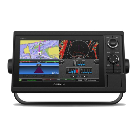
See the Important Safety and Product Information guide in the product box for product warnings and other important information. Not all features are available on all models. AQUAMAP Dimensions AQUAMAP 10x2 Series Keys Hold to turn the device on or off. 316.8 mm 68.5 mm... -
Page 12: Protective Cover
To remove the cover, hold the cover at the tab , and pull forward. cards to record Garmin Quickdraw™ Contours mapping, record sonar (with a compatible transducer), and transfer data such as waypoints and routes to another compatible AQUAMAP or a computer. -
Page 13: Software Update
8 Double-click the downloaded file. 3 Press the card in until it clicks. A Garmin folder containing the software update is created in the selected 4 Close the door. location. A dialog box opens to assist in transferring the software update to a memory card. -
Page 14: Gps Satellite Signals
For more information about GPS, go to Garmin.com/aboutGPS. Selecting the GPS Source You can select your preferred source for GPS data, if you have more than one GPS source. -
Page 15: Customizing Pages
Customizing Pages • To customize the data shown on the screen, select Overlays, and select an option. Adding an Item to the Favorites Screen • To resize the information areas shown on the screen, use the arrow keys, and press FOCUS to exit. From the Home screen, highlight an item, and hold SELECT to add it to your Favorites screen. -
Page 16: Resetting The Station Layouts
• To turn on other data bars, like the media controls, select Top Bar or 2 Select a preset. Bottom Bar, and select the necessary options. 3 Select an option: 3 Select Done. • To rename the preset, select Rename, enter a name, and select Done. •... -
Page 17: Adjusting The Backlight
Charts and 3D Chart Views Adjusting the Backlight 1 Select Settings > System > Sounds and Display > Backlight. The charts and 3D chart views that are available depend on the map data and accessories used. TIP: Press from any screen to open the backlight settings. 2 Adjust the backlight. -
Page 18: Nav. Chart And Offshore Fishing Chart
for depth recognition. This chart is best for offshore deep-sea fishing. NOTE: The offshore Fishing chart is available with premium charts, in some areas. Radar Overlay: Superimposes radar information on the Nav. chart or the Fishing chart, when AQUAMAP is connected to a radar. This feature is not available with all models. -
Page 19: Measuring A Distance On The Chart
Measuring a Distance on the Chart The distance and bearing appear on the screen. Press SELECT to measure from a location other than your current location. 1 From a chart or the Radar overlay, select a location. • To view tide, current, celestial, chart notes, or local services information 2 Press SELECT >... -
Page 20: Viewing Tide Station Information
Selecting a Map chart settings. If your product has both BlueChart g2 and Garmin LakeVü™ HD built-in An indicator for a tide station appears on the chart as a vertical bar graph with maps, you can select which map to use. Not all models have both types of an arrow. -
Page 21: Automatic Identification System
2 Select an option: Target is lost. A green X indicates that the AIS transmission from the • When you are on an inland lake, select LakeVü™ HD. vessel is lost, and the AQUAMAP displays a message banner asking whether the vessel should continue to be tracked. If you discontinue •... -
Page 22: Showing Ais And Marpa Vessels
course line does not appear. Changes in the speed, course over ground, or • To show MARPA-tagged vessels, select MARPA > Show. rate of turn information transmitted by the vessel can impact the calculation of • To show details about AIS-activated and MARPA- tagged vessels, the projected course line. -
Page 23: Turning Off Ais Reception
Rescue Transmitters (SART), Emergency Position Indicating Radio Beacons • To receive or ignore Man Overboard (MOB) test signals, select AIS- (EPIRB), and other man overboard signals. MOB Test. Distress signal transmissions are different than standard AIS transmissions, • To receive or ignore Search and Rescue Transponder (SART) test signals, select AIS-SART Test. -
Page 24: Marks, Wpts & Tracks Settings On The Charts And Chart Views
Chart Appearance: Adjusts the appearance of the different charts and 3D require external accessories or applicable premium charts. chart views. This may appear in the Chart Setup menu. From the Nav. chart or Fishing chart, select MENU > Chart Setup. Edit Overlays: Adjusts the data shown on the screen. -
Page 25: Laylines Settings
From a chart or 3D chart view, select MENU > Chart Appearance or MENU NOTE: This setting affects only the appearance of hazard colors for the > Chart Setup > Chart Appearance. Mariner’s Eye 3D chart view. It does not affect the safe water depth Auto Guidance setting or the sonar shallow water alarm setting. -
Page 26: Fish Eye 3D Settings
GPS position, and a speed above 32 km/h (20 mph). Tracks: Shows tracks. You can view Garmin Quickdraw Contours in a combination screen or as a Sonar Cone: Shows a cone that indicates the area covered by the single view on the map. -
Page 27: Adding A Label To A Garmin Quickdraw Contours Map
4 Sign in to your Garmin Connect account. 5 Select Marine in the upper-right to open the Garmin Quickdraw widget. TIP: Make sure you have a memory card in your computer to share Garmin NOTE: This feature is not available on all models. -
Page 28: Garmin Quickdraw Contours Settings
Downloading Garmin Quickdraw Community Maps Garmin Quickdraw Contours Settings You can download Garmin Quickdraw Contours maps that other users have created and shared with the Garmin Quickdraw Community. 1 Insert the memory card into your computer. 2 Access the Garmin Quickdraw Community. -
Page 29: Navigation With Aquamap
Navigation with AQUAMAP Survey Coloring: Sets the color of the Garmin Quickdraw Contours display. When this setting is turned on, the colors indicate the quality of the CAUTION recording. When this setting is turned off, the contour areas use standard map colors. -
Page 30: Basic Navigation Questions
4 Select the destination. When you are using a compatible Garmin autopilot connected to the Selecting a Destination Using the Nav. chart AQUAMAP using NMEA 2000 , the autopilot follows the Auto Guidance ® route. From the Nav. chart, select a destination. -
Page 31: Creating A Waypoint On The Sonar Screen
1 From a Nav. chart or 3D chart view, select MENU > Marks, Wpts & Marking an SOS Location Tracks > Marks & Waypoints. You can mark an SOS location. When a Garmin VHF radio is connected 2 Select a waypoint. using NMEA 2000, you can select different SOS types, such as Man- Overboard and Piracy. -
Page 32: Browsing For And Navigating To A Saved Waypoint
Browsing for and Navigating to a Saved Waypoint Deleting a Waypoint or an MOB 1 From a Nav. chart or 3D chart view, select MENU > Marks, Wpts & CAUTION Tracks > Marks & Waypoints. The Auto Guidance feature is based on electronic chart information. That 2 Select a waypoint or an MOB. -
Page 33: Tracks
Tracks and enter the time interval. • To record the track plot based on a variance from your course, select A track is a recording of the path of your boat. The track currently being Resolution > Change, and enter the maximum error allowed from the recorded is called the active track, and it can be saved. -
Page 34: Viewing A List Of Saved Tracks
2 Select an option: 1 From a chart or a 3D chart view, select MENU > Marks, Wpts & Tracks > Saved Tracks. • Select the time the active track began. 2 Select a track. • Select Entire Log. 3 Select Follow Track. 3 Review the course indicated by the colored line. -
Page 35: Creating And Saving A Route
Editing a Saved Route 2 Select SELECT > Navigate To > Route To. 3 Select the location of the last turn before the destination. You can change the name of a route or change the turns the route contains. 4 Select SELECT > Add Turn. 1 Select NAV INFO >... -
Page 36: Browsing For And Navigating Parallel To A Saved Route
6 Follow the magenta line along each leg in the route, steering to avoid land, 8 Follow the magenta line along each leg in the route, steering to avoid land, shallow water, and other obstacles. shallow water, and other obstacles. 7 If you are off course, follow the purple line (corrected course) to go to your 9 If you are off course, follow the purple line (corrected course) to go to your destination, or steer back to the magenta line (direct course). -
Page 37: Creating And Saving An Auto Guidance Path
4 Select Start Navigation. • To save the path, select Done. 5 Follow the magenta line, steering to avoid land, shallow water, and other Adjusting a Saved Auto Guidance Path obstacles. 1 Select NAV INFO > User Data > Routes & Auto Guidance. NOTE: When using Auto Guidance, a gray segment within any part of the 2 Select a path, and select Review >... - Page 38 Adjusting the Distance from Shore water depth or an unknown obstacle height, the Auto Guidance path is not calculated in that area. If an area at the beginning or the end of an Auto The Shoreline Distance setting indicates how close to the shore you want the Guidance path is shallower than the Preferred Depth or lower than the Auto Guidance line to be placed.
-
Page 39: Boundaries
result, the AQUAMAP may not reposition the Auto Guidance line, unless active boundary data to the data fields on the chart. the destination selected requires navigation through a narrow waterway. Creating a Boundary 8 Select an option: 1 Select NAV INFO > User Data > Boundaries > New. •... -
Page 40: Setting A Boundary Alarm
You can share waypoints, tracks, and routes with all compatible devices connected to the Garmin Marine Network (Ethernet) automatically. NOTE: This feature is not available on all models. Select Settings > Preferences > User Data Sharing > On. -
Page 41: Sailing Features
Sailing Features boat must reduce speed to avoid a penalty for reaching the start line before the timer expires. Setting the Vessel Type When the end point is on the start line, the line is white. This indicates the boat is moving at an optimal speed to reach the start line when the timer You can select your boat type to configure the AQUAMAP settings and to use expires. -
Page 42: Starting The Race Timer
Starting the Race Timer the wind sensor. The Manual option calculates the laylines using manually entered windward and leeward angles. The race timer is added to the Sail Racing combination screen by default. Windward Ang.: Allows you to set a layline based on the windward sailing 1 From the Sail Racing combination screen, select Start. -
Page 43: Sailboat Autopilot Operation
2000 or NMEA 0183 wind sensor to the autopilot. Setting the Wind Hold Type For advanced autopilot configuration, see the installation instructions included with your autopilot. 1 From the autopilot screen, select MENU > Autopilot Setup > Wind Hold Type. 2 Select Apparent or True. -
Page 44: Heading Line And Angle Markers
Tacking and Gybing from Wind Hold Setting the Heading and Course Over Ground Lines Before you can engage wind hold, you must have a wind sensor installed. You can show the heading line and the course over ground (COG) line on the chart. -
Page 45: Sonar Fishfinder
When properly connected to a transducer, your compatible AQUAMAP can connected. be used as a fishfinder. AQUAMAP models without an xsv or xs in their names require a Garmin sounder module and transducer to display sonar The full-screen Traditional sonar view show a large image of the sonar information. -
Page 46: Traditional 50/77/200 Khz Sonar
Conversely, higher frequencies with narrower beam angle would result in higher resolution images with better target separation. Garmin ClearVü Sonar View NOTE: To receive Garmin ClearVü scanning sonar, you need a compatible transducer. Garmin ClearVü high-frequency sonar provides a detailed picture of the fishing environment around the boat in a detailed representation of structures the boat is passing over. -
Page 47: Clearvü Scanning Sonar
ClearVü Scanning Sonar SideVü sonar, you need a compatible SideVü transducer. The Garmin ClearVü scanning sonar technology emits two narrow beams SideVü scanning sonar technology shows you a picture of what lies to the with CHIRP technology, similar to the shape of the beam in a copying sides of the boat. -
Page 48: Sidevü Scanning Technology
TIP: To reset the pin and measure from the current location of the pin, select The transducer on your vessel Measure Distance. Trees Panoptix Sonar Views Old tires NOTE: Not all models support Panoptix transducers. Logs To receive Panoptix sonar, you need a compatible AQUAMAP and a Distance from the side of the boat compatible transducer. -
Page 49: Livevü Forward Sonar View
RealVü 3D Historical Sonar View Panoptix down view history in a scrolling sonar view This sonar view provides a three-dimensional view of what is behind your Boat boat as you are moving and shows the entire water column in 3D, from the Range bottom to the top of the water. -
Page 50: Frontvü Sonar View
Before you can select the transducer type, you must know what kind of Fish transducer you have. Bottom This AQUAMAP is compatible with the Garmin ClearVü™ transducer as well Range as a range of accessory transducers including Garmin GT transducers, which are available at Garmin.com. For information about compatible transducers, go to Garmin.com/transducers. -
Page 51: Calibrating The Compass
AQUAMAPs and transducers are mounted on your boat. For example, 4 Follow the on-screen instructions. from a transducer with Garmin ClearVü mounted at the back of the boat, you can view the sonar data using the 922 mounted at the front of your boat. -
Page 52: Selecting A Sonar Source
For example, if you • To allow the AQUAMAP to adjust the gain or brightness automatically, have two sources for Garmin ClearVü, you can select the source to use from select an automatic option. -
Page 53: Selecting Frequencies
you to see deeper with the lower frequency return and, at the same time, see operation and rough sea conditions. Bottom definition and thermocline more detail from the higher frequency return. definition can be better when using a higher frequency. Lower frequencies use wider beam widths, which can let the fisherman see Selecting Frequencies more targets, but could also generate more surface noise and reduce bottom... -
Page 54: Auto
• To lock the screen to a specific depth and range, select Shift Zoom. This is a unique sonar zoom technology from Garmin. It displays the selected depth and range of sonar to fill the screen in more accuracy and detail. In •... -
Page 55: Traditional, Garmin Clearvü, And Sidevü Sonar Setup
From an applicable sonar view, select MENU > Sonar Setup / ClearVü aspect ratio and appear less distorted. When viewing Garmin ClearVü Setup / SideVü Setup. - Page 56 (A) Interference from other sonar (B) Electrical interference Color Limit: Hides part of the color palette to help eliminate fields of weak clutter. Medium High By setting the color limit to the color of the undesired returns, you can Interference Setting eliminate the display of undesired returns on the screen.
-
Page 57: Sonar Appearance Settings
Sonar Appearance Settings of sound, so that the echoes from fish schools of the same size are displayed in the same color. Avoid excessive TVG; weak echoes may not From an applicable sonar view, select MENU > Sonar Setup / ClearVü be displayed. -
Page 58: Sonar Alarms
The a-scope is a vertical flasher along the right side of the view, showing vessel is less than the specified value, which can help you avoid running you what is underneath the transducer right now. You can use the a-scope aground. -
Page 59: Transducer Installation Settings
defines the edges of the targets but may allow more noise. A longer filter creates softer target edges and may also reduce noise. This option is available on the Traditional sonar view only. Flip Left/Right: Switches the SideVü view orientation from left to right. This option is available on the SideVü... -
Page 60: Playing Sonar Recordings
4 Select Delete. Playing Sonar Recordings Before you can play back the sonar recordings, you must download and install the HomePort™ application and record sonar data onto a memory card. 1 Remove the memory card from the device. Gain: Controls the level of detail and noise shown on the sonar screen. 2 Insert the memory card into a card reader attached to a computer. -
Page 61: Livevü And Frontvü Sonar Settings
Press BACK to resume. bottom can appear on the screen as long as it appears within the range you have set. Manually reducing this option can reduce the effectiveness Sonar Setup: Adjusts the setup of the transducer and the appearance of the of the FrontVü... -
Page 62: Realvü Appearance Settings
alarm. column. A higher color gain value also allow you to differentiate low intensity returns higher in the water column, but this causes a loss in the 1 From the FrontVü sonar view, select MENU > FrontVü Alarm. differentiation of the returns at the bottom. You can select a lower color 2 Select On. - Page 63 RealVü 3D Forward sonar views. 1 Measure the horizontal distance from the transducer to the bow. Beam Width: Sets the width of the down view Panoptix transducer beam. Narrow beam widths allow you to see deeper and farther. Wider beam widths allow you to see more coverage area.
-
Page 64: Radar
5 Select MENU > Transmit Radar. energy. When you connect your compatible AQUAMAP to an optional Garmin marine Stopping the Transmission of Radar Signals radar, such as a GMR™ Fantom™ 6 radar or a GMR 24 xHD, you can view From a radar screen, select MENU >... -
Page 65: Adjusting The Radar Range
signals. 1 From a radar screen, press the knob. NOTE: GMR Fantom and xHD2 radar models support two no-transmit zones. 2 If necessary, press FOCUS to select a radar view. Other GMR radar models support one no-transmit zone. 3 Turn the knob to increase or decrease the range. Tips for Selecting a Radar Range •... -
Page 66: Enabling A Guard Zone
Defining a Partial Guard Zone The moving targets are color-coded so you can tell at a glance which targets are heading your way and which are heading away from you. On most You can define the boundaries of a guard zone that does not completely color schemes, green indicates the target is moving away from you and red surround your boat. -
Page 67: Marpa Targeting Symbols
Removing a MARPA Tag from a Targeted Object tagged object and provides you with information about the object, including the range, bearing, speed, GPS heading, nearest approach, and time 1 From a radar screen, select a MARPA target. to nearest approach. MARPA indicates the status of each tagged object 2 Select MARPA Target >... -
Page 68: Vrm And Ebl
You can adjust the diameter of the VRM and the angle of the EBL, which moves the intersection point of the VRM and the EBL. The VRM and the EBL When you connect your AQUAMAP to an optional Garmin marine radar, you configured for one mode are applied to all other radar modes. -
Page 69: Echo Trails
Turning on Echo Trails network. If a heading sensor is not available, the boat heading is based on GPS tracking data. From a radar screen, select MENU > Radar Options > Echo Trails > GPS tracking data indicates the direction in which the boat is moving, not Display. -
Page 70: Adjusting Gain On The Radar Screen Manually
Low or Auto High. 6 Minimize the appearance of nearby large objects, if necessary. • To adjust the gain automatically to show birds over the surface of the 7 Minimize the appearance of side-lobe echoes, if necessary. water, select Auto Bird. Minimizing Nearby Large-Object Interference NOTE: This option is not available on xHD open array or HD/HD+ radome models. -
Page 71: Adjusting Sea Clutter On The Radar Screen Manually
Adjusting Rain Clutter on the Radar Screen Clutter caused by choppy sea conditions. The radar antenna’s vertical beamwidth is designed to see the water surface’s targets even during the vessel is rolling. By this design the radar also will detect the rain clutter such as rain, snow and hail etc in the same manner as the normal targets. -
Page 72: Radar Options Menu
From a Radar screen or the Radar overlay, select MENU > Radar Setup Source: Selects the radar source when more than one radar is connected to > Crosstalk Rej.. the network. Chart Display: Shows the chart under the radar image. Radar Options Menu When enabled, the Chart Setup menu appears. -
Page 73: Radar Installation Settings
reference, to help you determine the bearing to an object shown on the 1 From a Radar screen or the Radar overlay, select MENU > Radar Setup radar screen. > Installation > Front of Boat. Nav Lines: Shows the navigation lines that indicate the course you have set 2 Turn the knob to adjust the offset. -
Page 74: Nav Info
Nav Info Celestial Information You can view information about sunrise, sunset, moonrise, moonset, moon phase, and the approximate sky view location of the sun and moon. The center of the screen represents the sky overhead, and the outermost rings represent the horizon. By default, the AQUAMAP shows celestial information for the present date and time. -
Page 75: Sharing And Managing User Data
3 Select GPX. Backing Up Data to a Computer To transfer data with Garmin devices again, select the ADM file type. 1 Insert a memory card into the card slot. 2 Select NAV INFO > User Data > Data Transfer > Save to Card. -
Page 76: Restoring Backup Data To Aquamap
7 Copy the backup file on the card and paste it to any location on the If you have a Garmin NMEA 2000 VHF radio connected to your AQUAMAP, computer. these features are also enabled. • The AQUAMAP allows you to quickly set up and send individual routine Restoring Backup Data to AQUAMAP call details to your Garmin VHF radio. -
Page 77: Incoming Distress Calls
Man-Overboard and SOS Distress Calls Initiated from the AQUAMAP 2 Select a position-report call. When your AQUAMAP is connected to a Garmin NMEA 2000 compatible 3 Select Review > New Waypoint. radio and you mark an SOS or man- overboard location, the radio shows the Distress Call page so you can quickly initiate a distress call. -
Page 78: Individual Routine Calls
Individual Routine Calls 1 From a chart or 3D chart view, select an AIS target. 2 Select AIS Vessel > Call with Radio. When you connect the AQUAMAP to a Garmin VHF radio, you can use the AQUAMAP™ 10x2/12x2 SERIES... -
Page 79: Warning Manager
The AQUAMAP sends information about the call to the radio. environment. To view the information, a compatible transducer or sensor must be connected to the network. 5 On your Garmin VHF radio, select Call. Warning Manager Viewing Messages 1 Select NAV INFO > Warning Manager. -
Page 80: Customizing Engine Gauge And Fuel Gauge Limits
Viewing Engine and Fuel Gauges 1 From an applicable gauges screen, select MENU > Edit Gauge Pages. 2 Select an option: Before you can view engine and fuel gauges, you must be connected to a NMEA 2000 network capable of sensing engine and fuel data. See the •... -
Page 81: Enabling Status Alarms For Engine Gauges
Synchronizing the Fuel Data with the Actual Vessel Fuel 2 Select First Engine. 3 Select the engine to display in the first gauge. You can synchronize the fuel levels in the AQUAMAP with the actual fuel in the vessel when you add fuel to your vessel. 4 Repeat for the remaining engine bars. -
Page 82: Configuring The Sailing Wind Gauge
Configuring the Sailing Wind Gauge Customizing the Close-Hauled Wind Gauge You can configure the sailing wind gauge to show true or apparent wind You can specify the range of the close-hauled wind gauge for both the upwind speed and angle. scale and the downwind scale. -
Page 83: Viewing Graphs
Viewing Graphs Batteries are listed along the top of the screen. Other sources of power, such as solar, alternator, converter, and wind generator, are listed along the left Before you can view graphs of various environmental changes, such as side. The items along the right side of the screen are devices that use the temperature, depth, and wind, you must have an appropriate transducer or batteries and other power sources. -
Page 84: Media Player
Media Player Button Description NOTE: The media player feature is not compatible with all AQUAMAP Press to select a source, such as a connected iPod or AM radio. models. Press to skip to the previous track or station. NOTE: Not all features are available on all connected media players. Press to play. -
Page 85: Playing Music
NOTE: The source menu appears only for devices that support multiple 1 From the media screen, select MENU > Media Menu > Audio Levels > media sources. Enable/Disable Zones. 2 Select a source. 2 Select a zone. Playing Music Muting the Media Volume 1 From the media screen, select Browsing for Music 2 If necessary, press SELECT. -
Page 86: Setting The Tuner Region
Selecting a Preset instructions on connecting a DAB adapter and antenna, see the installation instructions provided with your adapter and antenna. 1 From an applicable media screen, select Presets. 2 Select a preset from the list. Setting the Tuner Region 3 Select Tune to Channel. -
Page 87: Changing Dab Stations
Selecting a DAB Preset from a List When scanning is complete, the first available station in the first ensemble found begins playing. 1 From the DAB media screen, select Browse > Presets > View Presets. NOTE: After the first scan is complete, you can select Scan again to re- 2 Select a preset from the list. -
Page 88: Viewing Video
PoE Isolation Coupler. You can connect multiple supported video cameras and up to two video encoders to the Garmin Marine Network. You can select and view up to four video sources at once. Select A/V, Gauges, Controls > Video. -
Page 89: Camera Settings
Naming Video Presets on a Networked Video Camera models. You may need to update the camera software to use this feature. 1 From a video screen, select MENU > Video Setup > Name. From the video screen, select MENU > Video Setup. 2 Enter preset name. -
Page 90: Creating A Combination With Video Functions
You may need to update the camera software to use this feature. 2 Select a layout. You can control the movements of the connected video cameras that support 3 Select a panel, select Video > Show All, and select a video source. panning, tilting, and zooming. -
Page 91: Autopilot
(heading hold). The system also allows manual steering and several modes of automatic-steering functions and patterns. When the AQUAMAP is connected to a compatible Garmin autopilot system, you can engage and control the autopilot from the AQUAMAP. -
Page 92: Autopilot Bar
Autopilot Bar From the autopilot screen, select MENU > Autopilot Setup > Shadow Drive > Enabled. Adjusting the Heading with the Helm With the autopilot engaged, manually steer the boat. The autopilot activates Shadow Drive mode. When you release the helm and manually maintain a specific heading for a Actual heading few seconds, the autopilot resumes a heading hold at the new heading. -
Page 93: Setting Up And Following The Zigzag Pattern
Setting Up and Following the Zigzag Pattern After you connect the VIRB action camera with the AQUAMAP, a new option is added to A/V, Gauges, Controls. You can start and stop recording on the You can use the zigzag pattern to steer the boat from port to starboard and VIRB action camera using the AQUAMAP. -
Page 94: Adding The Virb Action Camera Controls To Other Screens
Deleting a VIRB Video Video Size: Sets the size or pixel dimensions of videos. Video FPS: Sets the frames per second. You can delete a video or image from the VIRB action camera. Photo Size: Sets the size or pixel dimensions of photos. 1 Open the VIRB video or image to delete. -
Page 95: Communication With Wireless Devices
1 Select Settings > Communications > Wi-Fi Network > Advanced > Connecting wireless devices allows you to use Garmin apps, including Channel. BlueChart Mobile and Garmin Helm™. See Garmin.com for more information. -
Page 96: Turning On And Off The Remote Backlight
Wi-Fi router. 1 Bring the a Garmin Nautix device within range (3 m) of the AQUAMAP. 1 Select Settings > Communications > Wireless Devices > Helm App. The device automatically looks for all compatible devices within range. -
Page 97: Device Configuration
You can view the software version, the basemap version, all supplemental Language: Sets the on-screen text language. map information (if applicable), the software version for an optional Garmin radar (if applicable), and the unit ID number. You may need this information to Navigation: Sets navigation preferences. -
Page 98: Units Settings
must have this setting turned on. Speed Sources: Sets the source for the speed readings. Auto Guidance: Sets the measurements for the Preferred Depth, Vertical Units Settings Clearance, and Shoreline Distance, when you are using some premium Select Settings > Preferences > Units. maps. -
Page 99: Communications Settings
change this setting while navigating. The available values for this setting 7 If you selected Near or Far in step 6, review the placement of the Auto are relative, not absolute. To ensure that the Auto Guidance line is placed Guidance line, and determine whether the line safely avoids known the appropriate distance from shore, you can assess the placement of the obstacles and the turns enable efficient travel. -
Page 100: Nmea 2000 Settings
Marine Network to receive data from and share data with other devices and AQUAMAPs that are compatible with the Marine Network. • To support the input or output of Garmin proprietary data for interfacing with Garmin software, select Garmin. Select Settings > Communications > Marine Network. -
Page 101: Setting Alarms
Setting Alarms functionality works with radar. The safe zone is used for collision avoidance and can be customized. Navigation Alarms 1 Select Settings > Alarms > Collision Alarm > On. Select Settings > Alarms > Navigation. A message banner appears and an alarm sounds when a MARPA-tagged object or an AIS-activated vessel enters the safe-zone area around your Arrival: Sets an alarm to sound when you are within a specified distance or boat. -
Page 102: Weather Alarms
Contour: Sets an alarm to sound when the transducer detects a suspended Temp. Offset: Allows you to set an offset value to compensate for the water target within the specified depth from the surface of the water and from the temperature reading from a NMEA 0183 water-temperature sensor or a bottom. -
Page 103: Setting The Water Temperature Offset
Before you can set the water temperature offset, you must have a NMEA 5 If the wheel turns freely, check the cable connections. 0183 water-temperature sensor or a temperature-capable transducer to 6 If you continue to get the message, contact Garmin product support. measure water temperature. Other Vessels Settings The temperature offset compensates for the temperature reading from a temperature sensor. -
Page 104: Restoring The Original Aquamap Factory Settings
10 Follow the on-screen instructions to set up your vessel. 11 Select Add. The Garmin Express application searches the memory card for the device information. 12 Select Add Device to register the device. When registration is complete, the Garmin Express application searches for additional charts and chart updates for your device. -
Page 105: Digital Switching
1 On the GRID remote input device, press + and HOME at the same time. 5 Select an image. A selection page opens on all of the AQUAMAPs on the Garmin Marine 6 Use the arrows to scroll through the images. -
Page 106: Capturing Screenshots
Check the fuse to make sure there is still a connection inside of the fuse. reader that is attached to a computer. You can test the fuse using a multimeter. If the fuse is good, the multimeter 2 From Windows Explorer, open the Garmin\scrn folder on the memory reads 0 ohm. card. -
Page 107: Specifications
**** The device withstands incidental exposure to water of up to 1 m for up to Max. power usage at 12 Vdc 34.8 W 30 min. For more information, go to Garmin.com/waterrating. Typical current draw at 12 Vdc 2.2 A Max. -
Page 108: Nmea 2000 Pgn Information
NMEA 2000 PGN Information Generator average basic AC quantities 065030 (GAAC) Type Description 126992 System time 059392 ISO acknowledgment 127488 Engine parameters: Rapid update 059904 ISO request 127489 Engine parameters: Dynamic 060928 ISO address claim 127493 Transmission parameters: Dynamic NMEA: Command, request, and 126208 acknowledge group function 127504 AC output status... -
Page 109: Nmea 0183 Information
PGRMM M: Map datum AGREEMENT. PLEASE READ THIS AGREEMENT CAREFULLY. PGRMZ Z: Altitude Garmin Ltd. and its subsidiaries (“Garmin”) grant you a limited license to use SDDBT DBT: Depth below transducer the software embedded in this device (the “Software”) in binary executable form in the normal operation of the product. -
Page 110: 物質宣言
物質宣言 structure, organization, and code of the Software, for which source code is not provided, are valuable trade secrets of Garmin and/or its third-party 有毒有害物质或元素 providers and that the Software in source code form remains a valuable trade 部件名称 铅 汞 镉... - Page 111 AQUAMAP™ 10x2/12x2 SERIES...
- Page 112 Printed in Taiwan October 2017 190-02217-00_0A...