Table of Contents
Advertisement
Quick Links
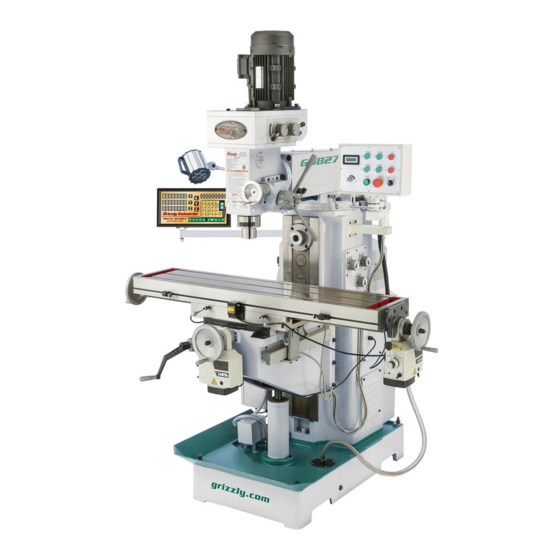
MODEL G0827
HORIZONTAL/VERTICAL MILL w/DRO
OWNER'S MANUAL
(For models manufactured since 11/17)
COPYRIGHT © JANUARY, 2018 BY GRIZZLY INDUSTRIAL
WARNING: NO PORTION OF THIS MANUAL MAY BE REPRODUCED IN ANY SHAPE
OR FORM WITHOUT THE WRITTEN APPROVAL OF GRIZZLY INDUSTRIAL, INC.
#BLJHKB18713 PRINTED IN CHINA
V1.01.18
Advertisement
Table of Contents

Related Manuals for Grizzly G0827


Summary of Contents for Grizzly G0827
- Page 1 OWNER'S MANUAL (For models manufactured since 11/17) COPYRIGHT © JANUARY, 2018 BY GRIZZLY INDUSTRIAL WARNING: NO PORTION OF THIS MANUAL MAY BE REPRODUCED IN ANY SHAPE OR FORM WITHOUT THE WRITTEN APPROVAL OF GRIZZLY INDUSTRIAL, INC. #BLJHKB18713 PRINTED IN CHINA V1.01.18...
- Page 2 This manual provides critical safety instructions on the proper setup, operation, maintenance, and service of this machine/tool. Save this document, refer to it often, and use it to instruct other operators. Failure to read, understand and follow the instructions in this manual may result in fire or serious personal injury—including amputation, electrocution, or death.
-
Page 3: Table Of Contents
Table of Contents INTRODUCTION ..........2 SECTION 6: MAINTENANCE ......44 Contact Info............ 2 Schedule ............44 Manual Accuracy ........... 2 Cleaning & Protecting ........44 Left Front View Identification ......3 Lubrication ........... 45 Right Front View Identification ....... 4 Adding/Changing Coolant ...... -
Page 4: Introduction
ID label (see below). This information is required for us to provide proper tech support, and it helps us determine if updated documenta- tion is available for your machine. Manufacture Date Serial Number Model G0827 (Mfd. Since 11/17) -
Page 5: Left Front View Identification
To reduce your risk of Spindle serious injury, read this entire manual BEFORE Motor using machine. Master Control Panel LED Work Light Horizontal Arbor Support Quill Lock Vertical Spindle Coolant Nozzle X-Axis Handwheel Electrical Splash Cabinet Base Coolant Pump Model G0827 (Mfd. Since 11/17) -
Page 6: Right Front View Identification
Lock Handle (1 of 2) Horizontal Spindle Horizontal Spindle Speed Selectors X-Axis Table Lock (1 of 2) Z-Axis Crank X-Axis Handwheel Y-Axis Handwheel Y-Axis Power X-Axis Feed Power Feed Y-Axis Table Lock (1 of 2) Model G0827 (Mfd. Since 11/17) -
Page 7: Controls & Components
E-STOP button must be reset first. E-STOP Button: Disables power to control panel and stops all machine functions. To reset, twist button clockwise until it pops out. K. Coolant Pump Switch: Starts/stops coolant pump. Model G0827 (Mfd. Since 11/17) - Page 8 W. Z-Axis Column Lock: When tightened, pre- vents Z-axis table movement for increased Q. Horizontal Spindle Speed Selector Knobs: rigidity during operations where the Z-axis Configures gearing inside column to produce should not move. various horizontal spindle speeds. Model G0827 (Mfd. Since 11/17)
- Page 9 IMPORTANT: Avoid contact with handwheel while rapid-traverse pressed; table AM. Y-Axis Limit Stops: Limits Y-axis table handwheel will rotate at a rapid rate. travel (one on either end of table). Model G0827 (Mfd. Since 11/17)
-
Page 10: Machine Data Sheet
MACHINE DATA SHEET Customer Service #: (570) 546-9663 · To Order Call: (800) 523-4777 · Fax #: (800) 438-5901 MODEL G0827 HORIZONTAL/VERTICAL MILL WITH DRO Product Dimensions: Weight................................2866 lbs. Width (side-to-side) x Depth (front-to-back) x Height................65 x 67 x 85 in. - Page 11 The information contained herein is deemed accurate as of 1/18/2018 and represents our most recent product specifications. Model G0827 PAGE 2 OF 3 Due to our ongoing improvement efforts, this information may not accurately describe items previously purchased. Model G0827 (Mfd. Since 11/17)
- Page 12 The information contained herein is deemed accurate as of 1/18/2018 and represents our most recent product specifications. Model G0827 PAGE 3 OF 3 Due to our ongoing improvement efforts, this information may not accurately describe items previously purchased. -10- Model G0827 (Mfd. Since 11/17)
-
Page 13: Section 1: Safety
Everyday ery. Never operate under the influence of drugs or eyeglasses are NOT approved safety glasses. alcohol, when tired, or when distracted. -11- Model G0827 (Mfd. Since 11/17) - Page 14 EXPERIENCING DIFFICULTIES. If at any time debris. Make sure they are properly installed, you experience difficulties performing the intend- undamaged, and working correctly BEFORE ed operation, stop using the machine! Contact our operating machine. Technical Support at (570) 546-9663. -12- Model G0827 (Mfd. Since 11/17)
-
Page 15: Additional Safety For Milling Machines
OFF to avoid a possible sudden startup use. This will prevent them from being thrown by once power is restored. the spindle upon startup. -13- Model G0827 (Mfd. Since 11/17) -
Page 16: Section 2: Power Supply
To reduce the risk of these hazards, avoid over- loading the machine during operation and make sure it is connected to a power supply circuit that meets the specified circuit requirements. -14- Model G0827 (Mfd. Since 11/17) -
Page 17: Grounding Instructions
Minimum Gauge Size ......14 AWG service personnel, and it must comply with Maximum Length (Shorter is Better)..50 ft. all local codes and ordinances. -15- Model G0827 (Mfd. Since 11/17) -
Page 18: Section 3: Setup
IMPORTANT: Save all packaging materials until you are completely satisfied with the machine and have resolved any issues between Grizzly or the shipping agent. You MUST have the original pack- aging to file a freight claim. It is also extremely helpful if you need to return your machine later. -
Page 19: Inventory
E. Drill Chuck B-16, 1–13mm ......1 —Chuck Key ..........1 Spindle Sleeve R8–MT#3 ......1 G. Drill Chuck Arbor R8–B16 ......1 Figure 11. Wood crate inventory. H. Spindle Sleeve MT#3–MT#2 ...... 1 Figure 10. Toolbox inventory. -17- Model G0827 (Mfd. Since 11/17) -
Page 20: Cleanup
Figure 12. T23692 Orange Power Degreaser. Repeat Steps 2–3 as necessary until clean, then coat all unpainted surfaces with a quality metal protectant to prevent rust. -18- Model G0827 (Mfd. Since 11/17) -
Page 21: Site Considerations
Shadows, glare, or strobe effects that may distract access restricted location. or impede the operator must be eliminated. Wall 30" Minimum Clearance 30" 94" Minimum Clearance 71" = Electrical Connection Figure 13. Minimum working clearances. -19- Model G0827 (Mfd. Since 11/17) -
Page 22: Lifting & Placing
Lifting Sling Rotate 180° counterclockwise so headstock faces forward, then re- install horizontal arbor support. Headstock (Faces Backward) Figure 14. Using lifting slings to lift and move mill. -20- Model G0827 (Mfd. Since 11/17) -
Page 23: Leveling
Figure 16. Example of a precision level methodology specified by the code. (Model H2683 shown). Lag Screw Flat Washer Machine Base Lag Shield Anchor Concrete Drilled Hole Figure 17. Popular method for anchoring machinery to a concrete floor. -21- Model G0827 (Mfd. Since 11/17) -
Page 24: Arbor/Chuck Assembly
Figure 18. Arbor/chuck assembly. Attempt to separate drill chuck and arbor by hand —if they separate, repeat Steps 3–4. -22- Model G0827 (Mfd. Since 11/17) -
Page 25: Assembly
Install handwheel handles onto X-axis and Y-axis handwheels (see Figure 19). Fine Downfeed Handwheel X-Axis Handle Handwheel Coarse Downfeed Handle Figure 21. Downfeed components assembled. Y-Axis Handwheel Figure 19. Locations of X-axis and Y-axis handwheels. -23- Model G0827 (Mfd. Since 11/17) -
Page 26: Power Connection
"wild wire" to the L2 terminal (see location on Page 67). The L2 terminal can handle power fluctuations because it is wired directly to the motor. -24- Model G0827 (Mfd. Since 11/17) - Page 27 Master recting potential problems. Power Switch Figure 23. Location of master power switch. Twist E-STOP button clockwise until it pops out—this resets it and allows mill to operate. -25- Model G0827 (Mfd. Since 11/17)
- Page 28 11. Press STOP button (vertical spindle) shown in Figure 26 and wait for spindle to com- pletely stop. Figure 27. Location of bolt for opening rear column cover. STOP Button (Vertical Spindle) Figure 26. Location of vertical spindle STOP button. -26- Model G0827 (Mfd. Since 11/17)
- Page 29 Y-axis power feed. Figure 28. Location of coolant pump switch. Congratulations! The Test Run of the mill is complete. Continue to the next page to per- form the Spindle Break-In and Inspections & Adjustments procedures. -27- Model G0827 (Mfd. Since 11/17)
-
Page 30: Spindle Break-In
RPM to highest speed. and avoid reducing life of belts. Refer to Tensioning/Replacing V-Belts on Page 53. -28- Model G0827 (Mfd. Since 11/17) -
Page 31: Section 4: Operations
Read books/magazines or get formal training before beginning any proj- ects. Regardless of the content in this sec- tion, Grizzly Industrial will not be held liable for accidents caused by lack of training. -29- Model G0827 (Mfd. Since 11/17) -
Page 32: Table Movement
Always keep table locked in place unless table movement is required for your oper- ation. Unexpected table and workpiece movement could cause tooling to bind with workpiece, which may damage tooling or Figure 30. Locations of graduated rings. workpiece. -30- Model G0827 (Mfd. Since 11/17) -
Page 33: Head Tilt
Note: Use angle scale shown in Figure 35 as a guide for setting tilt angle. Hex Nut (1 of 3) Retighten hex nuts securing head to ram before resuming operation. Figure 35. Head tilting controls. -31- Model G0827 (Mfd. Since 11/17) -
Page 34: Installing/Removing Tooling
(2 of 4) and a ⁄ "-20 drawbar. The Model G0827 includes the following vertical spindle tools (see Figure 39): A. B16 Drill Chuck w/R8–B16 Arbor. Refer to Arbor/Chuck Assembly on Page 22. B. R8–MT#3 Spindle Sleeve. Used for MT#3 tools and will accommodate tools with a tang. - Page 35 Loosen drawbar a couple of turns, then tap top of it with a brass hammer to knock taper between spindle and tooling loose. Support tooling with one hand, then com- pletely unthread drawbar from tooling. -33- Model G0827 (Mfd. Since 11/17)
- Page 36 Loosen locking bolt on side of arbor sup- for simple to very complex cutting operations. port, and slide support off ram dovetail way (see Figure 40). The Model G0827 includes the following horizon- tal spindle tools (see Figure 39): Ram Rotation A. 1 ⁄...
- Page 37 (see Figure 42). Brass Bushing Tooling Right-Hand Arbor Nut Figure 42. Horizontal arbor and cutter installed. -35- Model G0827 (Mfd. Since 11/17)
-
Page 38: Spindle Speed
Also, there are a large number of easy-to-use spindle speed calculators that can be found on the internet. These sources will help you take into account all applicable variables to determine the best spindle speed for the operation. -36- Model G0827 (Mfd. Since 11/17) - Page 39 Range (II) High/Low Range Selector Range Knob Figure 46. Location of high/low range selector. Figure 49. Location of horizontal spindle speed and range knobs. Spindle Speed Selectors Figure 47. Location of spindle speed selectors. -37- Model G0827 (Mfd. Since 11/17)
-
Page 40: Using Spindle Downfeed Controls
Quill Lock: Secures the quill in place for increased stability during milling operations. Typically only used after first positioning spindle/cutter with fine downfeed handwheel. -38- Model G0827 (Mfd. Since 11/17) -
Page 41: Fine Downfeed
Handwheel Using graduated dial to gauge spindle move- ment, rotate fine downfeed handwheel clock- wise 0.010". Tighten quill lock. Turn mill ON and perform cutting pass. Quill Lock Thumbscrew Figure 51. Fine downfeed controls. -39- Model G0827 (Mfd. Since 11/17) -
Page 42: Section 5: Accessories
To reduce this risk, only install accessories their lubricity under a variety of conditions—as recommended for this machine by Grizzly. well as reduce chatter or slip. Buy in bulk and save with 1- or 5-gallon quantities. - Page 43 Figure 57. T10168 3" Boring Head Set. Figure 59. Model SB1349 South Bend 16-Pc. R-8 Collet Set. www.grizzly.com 1-800-523-4777 order online at or call -41- Model G0827 (Mfd. Since 11/17)
- Page 44 ⁄ " T-slots, two locking screws, and pre- cision base. ⁄ " mounting slots. Figure 64. H7527 6" Rotary Table w/Div. Plates. Figure 62. G5758 Tilt Table. www.grizzly.com 1-800-523-4777 order online at or call -42- Model G0827 (Mfd. Since 11/17)
- Page 45 H5931—4-Pc Center Drill Set 82° Double ended HSS Center Drills are precision ground. Includes sizes 1-4. Figure 70. G7066 5" Tilting/Swiveling Milling Vise. Figure 67. H5930 4-pc Center Drill Set 60°. www.grizzly.com 1-800-523-4777 order online at or call -43- Model G0827 (Mfd. Since 11/17)
-
Page 46: Section 6: Maintenance
Gun Treatment, SLIPIT , or Boeshield T-9 (see ® ® • Missing or open belt guards/door. Figure 71 and the Grizzly catalog or website). • Coolant not flowing correctly. • Any other unsafe condition. Daily Before Operations • Press the E-STOP button on the control panel to prevent high-speed spindle startup when connected to power. -
Page 47: Lubrication
Hex Wrench 8mm ..........1 Drain Pan (1 Gallon or Larger) ......1 Pump-Type Oil Can with Plastic or Rubber Tip . 1 Mineral Spirits ........As Needed Shop Rags ......... As Needed Brush ..............1 -45- Model G0827 (Mfd. Since 11/17) - Page 48 Figure 74. Column oil fill and drain locations. Hold drain pan under drain plug and remove drain plug. Allow old oil to drain into drain pan. Replace and tighten drain plug shown in Figure 74. -46- Model G0827 (Mfd. Since 11/17)
-
Page 49: Ball Oilers
Proper lubrication of ball oilers is done with a pump-type oil can that has a cone tip (see Page 40 for offerings from Grizzly). We do not recommend using metal needle or lance tips, as they can push the ball too far into the oiler, break the spring seat, and lodge the ball in the oil galley. - Page 50 Add 1–2 pumps from an oil can between spindle spline and top of quill. Replace circular cover and run vertical spin- dle for a few minutes to distribute oil in Figure 81. Horizontal spindle arbor support ball bearings. oiler. -48- Model G0827 (Mfd. Since 11/17)
-
Page 51: Table Leadscrews
When dry, use a clean brush to apply a thin coat of oil to the leadscrew threads, then move the table through the X-, Y-, and Z-axis paths to dis- tribute the oil. -49- Model G0827 (Mfd. Since 11/17) -
Page 52: Ram Ways
Figure 88. Location of Z-axis bevel gears. When dry, use a clean brush to apply a thin coat of grease to the teeth, then move the table up and down to evenly distribute the grease. -50- Model G0827 (Mfd. Since 11/17) -
Page 53: Adding/Changing Coolant
10. Repeat Steps 1–9 for Y-axis power feed. when checking, adding, or changing coolant. Coolant Reservoir Capacity ..4.75 Gal. (18L) Running coolant pump without adequate coolant in reservoir may permanently damage coolant pump, which will not be covered by warranty. -51- Model G0827 (Mfd. Since 11/17) -
Page 54: Changing Coolant
Tip: Place a couple of magnets inside res- ervoir under return screen to collect metal particles and keep them out of coolant pump. Re-install return screen before resuming mill- ing operations. -52- Model G0827 (Mfd. Since 11/17) -
Page 55: Tensioning/Replacing V-Belts
Nuts Follow Steps 4–5 in Tensioning V-Belts procedure to set correct belt tension. Motor Bracket Close and secure rear column cover. Figure 92. Location of hex nuts for adjusting V-belt tension. -53- Model G0827 (Mfd. Since 11/17) -
Page 56: Machine Storage
Cover and place machine in a dry area that is out of direct sunlight and away from haz- ardous fumes, paint, solvents, or gas. Fumes and sunlight can bleach or discolor paint and plastic parts. -54- Model G0827 (Mfd. Since 11/17) -
Page 57: Section 7: Service
7. Replace loose pulley. 8. Gearbox at fault. 8. Select appropriate gear ratio; replace broken or slipping gears. 9. Motor bearings at fault. 9. Test by rotating shaft; rotational grinding/loose shaft requires bearing replacement. -55- Model G0827 (Mfd. Since 11/17) - Page 58 1. Poor spindle bearing lubrication. 1. Lubricate spindle bearings. 2. Mill operated at high speeds for extended 2. Allow mill to cool. period. 3. Spindle bearings too tight. 3. Properly adjust spindle bearing preload. -56- Model G0827 (Mfd. Since 11/17)
- Page 59 2. Inspect circuit boards, sensors, plugs, and wiring connections. Replace/repair as necessary. DRO reading is 1. Initial reading incorrect. 1. Zero/Reset DRO at beginning point. incorrect. 2. Sensor at fault. 2. Test/replace sensor as necessary. -57- Model G0827 (Mfd. Since 11/17)
-
Page 60: Tramming Mill Head
Dial Test Indicator Figure 95. Dial test indicator mounted. (with at least 0.0005" resolution) ....1 Indicator Holder (mounted on the quill/spindle) ....1 Precision Parallel Block (at least 9" in length) ........1 -58- Model G0827 (Mfd. Since 11/17) - Page 61 Rotate spindle by hand so that indicator point rests on one end of parallel block, as illus- trated in Figures 95–96, then zero dial. Figure 97. Parallel block and indicator positioned for the Y-axis measurement (top view). -59- Model G0827 (Mfd. Since 11/17)
-
Page 62: Adjusting Leadscrew Backlash
Loosen top screw, and tighten bottom screw until slightly snug. Re-tighten top screw to lock bottom screw setting. Check amount of backlash by rotating X-axis handwheel. -60- Model G0827 (Mfd. Since 11/17) -
Page 63: Adjusting Gibs
Hex Wrench 10mm ..........1 Open-End Wrench 19mm ........1 Re-tighten rear spanner nut to lock front spanner nut setting. Check amount of backlash by rotating Y-axis handwheel. Repeat Steps 3–5 if necessary. -61- Model G0827 (Mfd. Since 11/17) - Page 64 (see Figure 101). Adjusting Locking Set Screws and Jam Nuts Screws Figure 101. Z-axis gib set screws (shown from right side of knee way). -62- Model G0827 (Mfd. Since 11/17)
-
Page 65: Section 8: Wiring
Technical Support at (570) 546-9663. The photos and diagrams included in this section are best viewed in color. You can view these pages in color at www.grizzly.com. -63- Model G0827 (Mfd. Since 11/17) -
Page 66: Wiring Overview
(as recommended) 125V ASONG Component Location RPM Sensor Vertical Spindle Motor Work Control Lamp Panel Y-Axis Power Feed X-Axis Power Feed Electrical Panel Coolant Horizontal Pump Spindle Motor (Inside) READ ELECTRICAL SAFETY -64- Model G0827 (Mfd. Since 11/17) ON PAGE 63! -
Page 67: Electrical Panel Wiring
Electrical Panel Wiring Figure 102. Electrical panel wiring. READ ELECTRICAL SAFETY -65- Model G0827 (Mfd. Since 11/17) ON PAGE 63! -
Page 68: Electrical Panel Wiring Diagram A
Electrical Panel Wiring Diagram A To Page 69 READ ELECTRICAL SAFETY -66- Model G0827 (Mfd. Since 11/17) ON PAGE 63! -
Page 69: Electrical Panel Wiring Diagram B
Electrical Panel Wiring Diagram B READ ELECTRICAL SAFETY -67- Model G0827 (Mfd. Since 11/17) ON PAGE 63! -
Page 70: Control Panel Wiring
Minger LA125H-BE101C LA125H-BE101C LA125H-BE102C Pump Switch POWER Light Minger LA125H-BE102C Minger LA125J-11 D206A EMERGENCY OFF Switch Master Control Panel (Viewed from Behind) Ground Figure 103. Control panel wiring. READ ELECTRICAL SAFETY -68- Model G0827 (Mfd. Since 11/17) ON PAGE 63! -
Page 71: Vertical Spindle Motor Wiring
Figure 104. Vertical spindle motor wiring. Electrical Panel Page 66 Horizontal Spindle Motor Wiring 220V Motor U1 V1 Figure 105. Horizontal spindle motor wiring. Electrical Panel Page 66 READ ELECTRICAL SAFETY -69- Model G0827 (Mfd. Since 11/17) ON PAGE 63! -
Page 72: Coolant Pump Wiring
Figure 106. Coolant pump wiring. Electrical Panel Page 66 DRO Wiring Electrical Panel Page 66 Figure 107. DRO wiring. X-Axis Scale 650mm Y-Axis Scale 300mm Z-Axis Scale 500mm (Viewed from Behind) READ ELECTRICAL SAFETY -70- Model G0827 (Mfd. Since 11/17) ON PAGE 63! -
Page 73: Section 9: Parts
Call (800) 523-4777 or visit www.grizzly.com/parts to check for availability. BUY PARTS ONLINE AT GRIZZLY.COM! -71- Model G0827 (Mfd. Since 11/17) Scan QR code to visit our Parts Store. - Page 74 P0827062 RIVET 3.5MM BLIND P0827034 SET SCREW M8-1.25 X 10 P0827063 COVER PLATE, STEEL P0827035 KEY 8 X 8 X 15 BUY PARTS ONLINE AT GRIZZLY.COM! -72- Model G0827 (Mfd. Since 11/17) Scan QR code to visit our Parts Store.
-
Page 75: Vertical Spindle
Vertical Spindle BUY PARTS ONLINE AT GRIZZLY.COM! -73- Model G0827 (Mfd. Since 11/17) Scan QR code to visit our Parts Store. - Page 76 129 P0827129 COARSE DOWNFEED LEVER HUB 159 P0827159 LOCK WASHER 6MM 130 P0827130 LEVER HANDLE 200L, M12-1.75 X 15 160 P0827160 HEX NUT M6-1 BUY PARTS ONLINE AT GRIZZLY.COM! -74- Model G0827 (Mfd. Since 11/17) Scan QR code to visit our Parts Store.
-
Page 77: Ram
P0827232 HEX BOLT M16-2 X 220 P0827216 WORM GEAR P0827233 FLAT WASHER 16MM P0827217 THRUST BEARING 51102 P0827234 HEX NUT M16-2 BUY PARTS ONLINE AT GRIZZLY.COM! -75- Model G0827 (Mfd. Since 11/17) Scan QR code to visit our Parts Store. -
Page 78: Base & Column
Base & Column 368 369 319-5 364 365 319-3 319-6 319-4 319-1 319-2 BUY PARTS ONLINE AT GRIZZLY.COM! -76- Model G0827 (Mfd. Since 11/17) Scan QR code to visit our Parts Store. - Page 79 DRO CONTROL BOX POWER CORD P0827339 COOLANT NOZZLE 385 P0827385 POWER CONTROL BOX POWER CORD P0827340 CAP SCREW M6-1 X 30 386 P0827386 SPLASH GUARD BUY PARTS ONLINE AT GRIZZLY.COM! -77- Model G0827 (Mfd. Since 11/17) Scan QR code to visit our Parts Store.
-
Page 80: Horizontal Spindle
Horizontal Spindle BUY PARTS ONLINE AT GRIZZLY.COM! -78- Model G0827 (Mfd. Since 11/17) Scan QR code to visit our Parts Store. - Page 81 CAP SCREW M6-1 X 20 P0827432 GEAR 26T P0827466 GASKET P0827433 GEAR 43T P0827467 GASKET P0827434 SHAFT P0827468 COLUMN SIDE COVER, LEFT BUY PARTS ONLINE AT GRIZZLY.COM! -79- Model G0827 (Mfd. Since 11/17) Scan QR code to visit our Parts Store.
-
Page 82: Table
Table 549 551 BUY PARTS ONLINE AT GRIZZLY.COM! -80- Model G0827 (Mfd. Since 11/17) Scan QR code to visit our Parts Store. - Page 83 X-AXIS GRADUATED DIAL 595 P0827595 PHLP HD SCR M3-.5 X 5 548 P0827548 SPANNER NUT 1-1/4-20 596 P0827596 Y-AXIS GRADUATED DIAL BUY PARTS ONLINE AT GRIZZLY.COM! -81- Model G0827 (Mfd. Since 11/17) Scan QR code to visit our Parts Store.
-
Page 84: Knee Spindle
Knee Spindle BUY PARTS ONLINE AT GRIZZLY.COM! -82- Model G0827 (Mfd. Since 11/17) Scan QR code to visit our Parts Store. - Page 85 668 P0827668 SET SCREW M5-.8 X 12 P0827634 HEX NUT M12-1.75 669 P0827669 LIMIT SWITCH CORD RETAINER P0827635 Z-AXIS GIB TOP BUY PARTS ONLINE AT GRIZZLY.COM! -83- Model G0827 (Mfd. Since 11/17) Scan QR code to visit our Parts Store.
-
Page 86: Electrical Box & Control Panel Components
720 P0827720 CONTACTOR SIEMENS 3TB41 24V 739 P0827739 FLAT WASHER 4MM 721 P0827721 ROTARY SWITCH CANSEN LW26-25 740 P0827740 BUTTON HD CAP SCR M4-.7 X 6 BUY PARTS ONLINE AT GRIZZLY.COM! -84- Model G0827 (Mfd. Since 11/17) Scan QR code to visit our Parts Store. -
Page 87: Accessories & Tools
P0827810 HEX WRENCH 6MM P0827822 DRIFT KEY P0827811 HEX WRENCH 5MM P0827823 WRENCH 8 X 10MM OPEN-ENDS P0827812 HEX WRENCH 4MM BUY PARTS ONLINE AT GRIZZLY.COM! -85- Model G0827 (Mfd. Since 11/17) Scan QR code to visit our Parts Store. -
Page 88: Labels & Cosmetics
ELECTRICITY WARNING LABEL P0827910 TOUCH-UP PAINT, GRIZZLY BEIGE P0827905 DISCONNECT POWER LABEL P0827911 TOUCH-UP PAINT, GRIZZLY GREEN P0827906 POWER TRAVERSE NOTICE BUY PARTS ONLINE AT GRIZZLY.COM! -86- Model G0827 (Mfd. Since 11/17) Scan QR code to visit our Parts Store. - Page 89 Would you recommend Grizzly Industrial to a friend? _____ Yes _____No Would you allow us to use your name as a reference for Grizzly customers in your area? Note: We never use names more than 3 times. _____ Yes _____No 10.
- Page 90 FOLD ALONG DOTTED LINE Place Stamp Here GRIZZLY INDUSTRIAL, INC. P.O. BOX 2069 BELLINGHAM, WA 98227-2069 FOLD ALONG DOTTED LINE Send a Grizzly Catalog to a friend: Name_______________________________ Street_______________________________ City______________State______Zip______ TAPE ALONG EDGES--PLEASE DO NOT STAPLE...
-
Page 91: Warranty & Returns
WARRANTY & RETURNS Grizzly Industrial, Inc. warrants every product it sells for a period of 1 year to the original purchaser from the date of purchase. This warranty does not apply to defects due directly or indirectly to misuse, abuse, negligence, accidents, repairs or alterations or lack of maintenance.