Table of Contents
Advertisement
For questions or help with this product contact Tech Support at (570) 546-9663 or techsupport@grizzly.com
The following changes were recently made since the owner's manual was printed:
•
Machine is shipped without blade guard installed.
Revised Assembly instructions on Page 21. The revised steps below replace existing Step 9.
•
IMPORTANT: YOU MUST INSTALL GUARD BEFORE OPERATING MACHINE THE FIRST TIME!
Aside from this information, all other content in the owner's manual applies and MUST be read and under-
stood for your own safety. IMPORTANT: Keep this update with the owner's manual for future reference.
For questions or help, contact our Tech Support at (570) 546-9663 or techsupport@grizzly.com.
Revised Assembly Steps
9.
Set fence to 90° and move it all the way back.
10. Remove pre-installed button head cap screw
and fender washer from bottom of cutterhead
guard shaft; then loosen shaft lock and insert
shaft into mounting hole, positioned so guard
rests against fence (see Figure 14).
Cutterhead Guard
Shaft Lock
Figure 14. Cutterhead guard components.
11. Position guard height as low as possible with-
out dragging on infeed table/rabbeting ledge
(approximately
⁄
1
16
en shaft lock to secure setting, then install
button head cap screw and fender washer.
WARNING: NO PORTION OF THIS MANUAL MAY BE REPRODUCED IN ANY SHAPE
OR FORM WITHOUT THE WRITTEN APPROVAL OF GRIZZLY INDUSTRIAL, INC.
READ THIS FIRST
Fence
" above infeed table), tight-
COPYRIGHT © NOVEMBER, 2019 BY GRIZZLY INDUSTRIAL, INC.
#BL20773 PRINTED IN TAIWAN
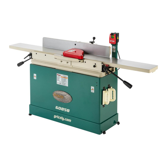
Model G0858
***IMPORTANT UPDATE***
For Machines Mfd. Since 07/19
and Owner's Manual Revised 06/19
The cutterhead guard is a critical safety
feature of this jointer. You MUST verify its
operation before using the jointer! Failure
to properly install this guard will greatly
increase risk of serious personal injury.
12. Verify proper operation of cutterhead guard
by setting fence to 90°, moving fence to rear
of table, then pulling cutterhead guard back
and letting it go. It should spring back over
cutterhead and contact fence without drag-
ging across outfeed table.
— If cutterhead guard does not spring back
over cutterhead and contact fence, or if it
drags across outfeed table, then it must
be adjusted (refer to Checking/Adjusting
Cutterhead Guard on Page 53 for
instructions).
Advertisement
Table of Contents

Related Manuals for Grizzly G0857


Summary of Contents for Grizzly G0857
- Page 1 ***IMPORTANT UPDATE*** For Machines Mfd. Since 07/19 and Owner's Manual Revised 06/19 For questions or help with this product contact Tech Support at (570) 546-9663 or techsupport@grizzly.com The following changes were recently made since the owner's manual was printed: •...
- Page 2 (For models manufactured since 07/19) 175370 COPYRIGHT © OCTOBER, 2018 BY GRIZZLY INDUSTRIAL, INC. REVISED JUNE, 2019 (BL) WARNING: NO PORTION OF THIS MANUAL MAY BE REPRODUCED IN ANY SHAPE OR FORM WITHOUT THE WRITTEN APPROVAL OF GRIZZLY INDUSTRIAL, INC.
- Page 3 This manual provides critical safety instructions on the proper setup, operation, maintenance, and service of this machine/tool. Save this document, refer to it often, and use it to instruct other operators. Failure to read, understand and follow the instructions in this manual may result in fire or serious personal injury—including amputation, electrocution, or death.
-
Page 4: Table Of Contents
Cleaning & Protecting ........35 Identification ........... 3 Lubrication ........... 36 Controls & Components ......... 4 Machine Data Sheet (G0857) ......6 SECTION 7: SERVICE ........37 Machine Data Sheet (G0858) ......8 Troubleshooting ........... 37 Setting/Replacing Knives (G0857) ....39 SECTION 1: SAFETY ........ -
Page 5: Introduction
Machine Differences and it helps us determine if updated documenta- tion is available for your machine. Models G0857 and G0858 are 3 HP, 8" x 76" joint- ers with the following differences: Model G0857 has a 4-knife cutterhead with •... -
Page 6: Identification
"per pass. d) Always use hold-down or push blocks when jointing material narrower than 3" or planing material thinner than 3". e) Never perform jointing, planing, or rabbeting cuts on pieces shorter than 10" in length. Model G0857/G0858 (Mfd. Since 07/19) -
Page 7: Controls & Components
H. Outfeed Table Adjustment Lever: Move up included). or down to adjust position of outfeed table (when outfeed table lock is loosened). Only B. STOP Paddle: Push to stop motor. used when setting outfeed table even with cutterhead knives/inserts. Model G0857/G0858 (Mfd. Since 07/19) - Page 8 Fence Lock Lever: Tighten to secure fence position along width of tables; loosen for fence adjustment. U. Fence Adjustment Knob: Rotate to move fence position forward/backward. (Fence lock lever must be loosened first.) Model G0857/G0858 (Mfd. Since 07/19)
-
Page 9: Machine Data Sheet (G0857)
Machine Data Sheet (G0857) MACHINE DATA SHEET Customer Service #: (570) 546-9663 · To Order Call: (800) 523-4777 · Fax #: (800) 438-5901 MODEL G0857 8" X 76" PARALLELOGRAM JOINTER WITH MOBILE BASE Product Dimensions: Weight................................365 lbs. Width (side-to-side) x Depth (front-to-back) x Height..............76 x 25 x 41-1/2 in. - Page 10 The information contained herein is deemed accurate as of 9/18/2018 and represents our most recent product specifications. Model G0857 PAGE 2 OF 3 Due to our ongoing improvement efforts, this information may not accurately describe items previously purchased. Model G0857/G0858 (Mfd. Since 07/19)
-
Page 11: Machine Data Sheet (G0858)
The information contained herein is deemed accurate as of 9/3/2019 and represents our most recent product specifications. Model G0858 PAGE 1 OF 3 Due to our ongoing improvement efforts, this information may not accurately describe items previously purchased. Model G0857/G0858 (Mfd. Since 07/19) - Page 12 The information contained herein is deemed accurate as of 9/3/2019 and represents our most recent product specifications. Model G0858 PAGE 2 OF 3 Due to our ongoing improvement efforts, this information may not accurately describe items previously purchased. Model G0857/G0858 (Mfd. Since 07/19)
-
Page 13: Section 1: Safety
Never operate under the influence of drugs or injury or blindness from flying particles. Everyday alcohol, when tired, or when distracted. eyeglasses are NOT approved safety glasses. -10- Model G0857/G0858 (Mfd. Since 07/19) - Page 14 Make sure they are properly installed, you experience difficulties performing the intend- undamaged, and working correctly BEFORE ed operation, stop using the machine! Contact our operating machine. Technical Support at (570) 546-9663. -11- Model G0857/G0858 (Mfd. Since 07/19)
-
Page 15: Additional Safety For Jointers
Straight knives should never project MAXIMUM CUTTING DEPTH. To reduce risk of more than ⁄ " (0.125") from cutterhead body. kickback, never cut deeper than ⁄ " per pass. -12- Model G0857/G0858 (Mfd. Since 07/19) -
Page 16: Section 2: Power Supply
To reduce the risk of these hazards, avoid over- loading the machine during operation and make sure it is connected to a power supply circuit that meets the specified circuit requirements. -13- Model G0857/G0858 (Mfd. Since 07/19) - Page 17 Minimum Gauge Size ......12 AWG all local codes and ordinances. Maximum Length (Shorter is Better)..50 ft. -14- Model G0857/G0858 (Mfd. Since 07/19)
-
Page 18: Section 3: Setup
IMPORTANT: Save all packaging materials until Keep children and pets away you are completely satisfied with the machine and from plastic bags or packing have resolved any issues between Grizzly or the materials shipped with this shipping agent. You MUST have the original pack- machine. -
Page 19: Inventory
—Knife Jig Feet ........2 —Knife Jig Rod ........1 K. Helical Cutterhead Accessories (G0858) —T-Handle Torx Driver T-25 ....2 —Torx Screws T-25 #10-32 x ⁄ ... 10 —Indexable Inserts 15 x 15 x 2.5mm ..5 -16- Model G0857/G0858 (Mfd. Since 07/19) -
Page 20: Hardware Recognition Chart
Hardware Recognition Chart USE THIS CHART TO MATCH UP HARDWARE DURING THE INVENTORY AND ASSEMBLY PROCESS. Flat Head Screw -17- Model G0857/G0858 (Mfd. Since 07/19) -
Page 21: Cleanup
Figure 8. T23692 Orange Power Degreaser. Repeat Steps 2–3 as necessary until clean, then coat all unpainted surfaces with a quality metal protectant to prevent rust. -18- Model G0857/G0858 (Mfd. Since 07/19) -
Page 22: Site Considerations
Only install in an Shadows, glare, or strobe effects that may distract access restricted location. or impede the operator must be eliminated. Wall Min. 30" for Maintenance 76" 25" Figure 9. Minimum working clearances. -19- Model G0857/G0858 (Mfd. Since 07/19) -
Page 23: Assembly
Test Run. If moving and placing jointer without power lifting equipment, carefully "walk" machine off the shipping pallet with the help of other people and roll it to its prepared location. Proceed to Step 4. -20- Model G0857/G0858 (Mfd. Since 07/19) - Page 24 Failure x 20 cap screws and (2) 8mm lock washers to do so will greatly increase risk of serious pre-installed on stand. personal injury. Note: Switch pedestal is mounted upside- down for shipping purposes. -21- Model G0857/G0858 (Mfd. Since 07/19)
-
Page 25: Knife-Setting Jig (G0857)
Figure 15, and secure with a hose clamp. Hose Clamp Dust Hose Figure 15. Example of dust hose attached to dust port. Tug hose to make sure it does not come off. A tight fit is necessary for proper performance. -22- Model G0857/G0858 (Mfd. Since 07/19) -
Page 26: Test Run
Connect machine to power supply. Push ON button to start machine. A correctly operating machine runs smoothly with little or no vibration or rubbing noises. Push STOP paddle to stop machine. Congratulations! The Test Run is complete. -23- Model G0857/G0858 (Mfd. Since 07/19) -
Page 27: Disabling & Locking Switch
4mm. With any padlock used to lock the switch, test the switch after installation to ensure that it is properly disabled. Padlock Shaft ON / START Button OFF / STOP Paddle Figure 16. Switch disabled by a padlock. -24- Model G0857/G0858 (Mfd. Since 07/19) -
Page 28: Section 4: Operations
Read books/magazines or get formal training before beginning any proj- ects. Regardless of the content in this sec- tion, Grizzly Industrial will not be held liable for accidents caused by lack of training. -25- Model G0857/G0858 (Mfd. Since 07/19) -
Page 29: Stock Inspection & Requirements
Cutting " Min. these may lead to injury or machine damage. Figure 18. Minimum stock dimensions for jointer. -26- Model G0857/G0858 (Mfd. Since 07/19) 10" Min. -
Page 30: Squaring Stock
Rip Cut on a Table Saw—Jointed edge Surface Plane on Jointer—Concave face of of workpiece is placed against a table saw workpiece is surface planed flat with jointer. fence and opposite edge cut off. Previously Jointed Edge -27- Model G0857/G0858 (Mfd. Since 07/19) -
Page 31: Surface Planing
Tip: When squaring up stock, cut opposite side of workpiece with a planer instead of the Removed jointer to ensure boths sides are parallel. Surface Figure 19. Example photo of a surface planing operation. -28- Model G0857/G0858 (Mfd. Since 07/19) -
Page 32: Edge Jointing
Tip: When squaring up stock, cut opposite Figure 20. Example photo of an edge jointing edge of workpiece with a table saw instead operation. of the jointer—otherwise, both edges of work- piece will not be parallel with each other. -29- Model G0857/G0858 (Mfd. Since 07/19) -
Page 33: Bevel Cutting
4" from moving cutterhead at any time during operation! Removed Repeat cutting process, as necessary, until Surface you are satisfied with the results. Figure 21. Example of fence set up for a bevel cut of 45°. -30- Model G0857/G0858 (Mfd. Since 07/19) -
Page 34: Rabbet Cutting
To minimize risk of injury and unnec- essary exposure to cutterhead, always keep cutterhead guard installed when pos- sible, and ALWAYS immediately replace it after performing rabbet cuts. -31- Model G0857/G0858 (Mfd. Since 07/19) -
Page 35: Setting Depth Of Cut
(see Figure 23), adjust the table height, and then tighten the lock to secure the setting. Infeed Table Table Lock Release Knob Infeed Table Adjustment Lever Figure 23. Infeed table controls. -32- Model G0857/G0858 (Mfd. Since 07/19) - Page 36 ", then pull and hold the table Stop Bolt more than release knob (see Figure 23) while lowering infeed table. Jam Nut Jam Nut ⁄ " Stop Bolt Jam Nut Figure 25. Positive stop bolts for infeed table. -33- Model G0857/G0858 (Mfd. Since 07/19)
-
Page 37: Section 5: Accessories
To reduce this risk, only install accessories recommended for this machine by Grizzly. NOTICE Refer to our website or latest catalog for additional recommended accessories. -
Page 38: Section 6: Maintenance
Clean and lubricate fence pivot points (Page 36). • Poly-V belt tension, damage, or wear. • Clean/vacuum dust buildup from inside stand and off of motor. Figure 30. Recommended products for protecting unpainted cast iron and steel. -35- Model G0857/G0858 (Mfd. Since 07/19) -
Page 39: Lubrication
Figure 32. T27914 Moly-D Machine & Way Oil. Clean Shop Rags ......As Needed Fence & Carriage Oil Type ..Grizzly T27914 or ISO 68 Equivalent Oil Amount ...........1–2 Drops Lubrication Frequency ..Monthly, or As Needed Clean fence pivot points and carriage ways (see Figure 31) with mineral spirits and shop rags, allow to dry, then lubricate with light machine oil. -
Page 40: Section 7: Service
6. Sharpen/replace knives (Page 40); rotate/replace inserts (Page 42). 7. Cutterhead bearings at fault. 7. Replace bearing(s). 8. Centrifugal switch at fault. 8. Adjust/replace centrifugal switch if available. 9. Motor bearings at fault. 9. Test/repair/replace. -37- Model G0857/G0858 (Mfd. Since 07/19) - Page 41 1. Align outfeed table with cutterhead knife/insert at (gouge in end of top dead center (Page 46). board that is uneven 2. Knives set too high (G0857). 2. Adjust height of knives evenly with outfeed table with rest of cut). (Page 40).
-
Page 42: Setting/Replacing Knives (G0857)
— If knives do not touch straightedge or they Open-End Wrench 10mm ........1 lift up at any position, then those knives need to be adjusted (refer to Setting/ Replacing Knives on Page 40). -39- Model G0857/G0858 (Mfd. Since 07/19) - Page 43 Rotate cutterhead pulley to provide good access to cutterhead knives. DISCONNECT MACHINE FROM POWER! Remove cutterhead guard or block it open. Lower infeed table to ⁄ " scale mark. Place knife jig on cutterhead, directly over a knife. -40- Model G0857/G0858 (Mfd. Since 07/19)
- Page 44 Tighten each gib bolt in the same alternating manner as you did in the previous step. 10. Make sure outfeed table is set even with the new knives at top dead center. 11. Replace cutterhead guard and cabinet rear access panel. -41- Model G0857/G0858 (Mfd. Since 07/19)
-
Page 45: Rotating/Replacing Helical Cutterhead Inserts (G0858)
Figure 30. Insert rotating sequence. Torx screws. Item(s) Needed Carbide Inserts 15 x 15 x 2.5mm ..As Needed Torx Head Screws T-25 #10-32 x ⁄ " As Needed Torque Wrench ..........1 T-25 Torx Bit ............1 -42- Model G0857/G0858 (Mfd. Since 07/19) -
Page 46: Checking/Adjusting Table Parallelism
Rotate motor pulley so that you can access cutterhead body with straightedge between the knives/inserts, as shown in Figure 44. Straightedge Outfeed Table Figure 44. Adjusting outfeed table even with cutterhead body (knife-style cutterhead shown). -43- Model G0857/G0858 (Mfd. Since 07/19) - Page 47 — If straightedge does not sit flat against both infeed and outfeed tables in any of the positions, then perform Adjusting Table Parallelism on Page 45. -44- Model G0857/G0858 (Mfd. Since 07/19)
- Page 48 Figure 48. Adjusting outfeed table even with outfeed table is parallel with cutterhead. cutterhead body (knife-style cutterhead shown). Repeat Step 3 with each remaining straight- edge position as many times as necessary until outfeed table is parallel with cutterhead. -45- Model G0857/G0858 (Mfd. Since 07/19)
-
Page 49: Setting Outfeed Table Height
Remove cutterhead guard, fence, and rear bushings under infeed table so straightedge access panel on stand. lies flat against both tables. G0857 Only: Make sure knife heights are set Black Lines Represent correctly (refer to Setting/Replacing Knives Straightedge Positions on Page 40). -
Page 50: Calibrating " Infeed Table Stop
Use outfeed table lever to set outfeed table Checking Adjusting 1/8 Infeed Table Stop so knife or insert barely touches straightedge, The infeed table on the Model G0857/G0858 has as shown in Figure 55. a built-in table stop that automatically sets depth of cut at ⁄... -
Page 51: Setting Fence Stops
Set to 45° Inward Replace table covers and re-install release knob. Calibrate depth-of-cut scale (refer Calibrating Depth-of-Cut Scale Page 50). Figure 59. Example of adjusting fence to 45° inward. -48- Model G0857/G0858 (Mfd. Since 07/19) - Page 52 Loosen jam nut on 90° stop cap screw and adjust cap screw until fence is exactly 90° while cap screw is resting on stop block (see Figure 60). Verify angle, then retighten jam nut. -49- Model G0857/G0858 (Mfd. Since 07/19)
-
Page 53: Calibrating Depth-Of-Cut Scale
Place a straightedge across infeed and outfeed tables. Adjust the infeed table until it is even with the outfeed table (see Figure 64). G0857 Straightedge Outfeed Infeed G0858 Straightedge Outfeed Infeed Figure 64. Infeed table even with outfeed table. -50- Model G0857/G0858 (Mfd. Since 07/19) -
Page 54: Tensioning/Replacing Belt
Follow Steps 4–5 in Tensioning Belt proce- (3 of 4 shown). dure to set correct belt tension. Press down on motor to keep tension on belt. Tighten motor mount fasteners (see Figure 66), and replace rear access panel. -51- Model G0857/G0858 (Mfd. Since 07/19) -
Page 55: Checking/Aligning Pulleys
Figure 69, when belt is properly pulley faces to check alignment. tensioned. Re-install fence, belt cover, and rear access Cutterhead panel on stand Pulley Belt Motor Pulley Figure 68. Checking pulley alignment (viewed from above). -52- Model G0857/G0858 (Mfd. Since 07/19) -
Page 56: Checking/Adjusting Cutterhead Guard
Fence Shaft Lock Figure 70. Cutterhead guard components. Holding guard height in place, tighten shaft lock to secure setting. Repeat Step 2 and, if necessary, repeat Steps 3–4 until cutterhead guard is properly adjusted. -53- Model G0857/G0858 (Mfd. Since 07/19) -
Page 57: Section 8: Wiring
Technical Support at (570) 546-9663. The photos and diagrams included in this section are best viewed in color. You can view these pages in color at www.grizzly.com. -54- Model G0857/G0858 (Mfd. Since 07/19) -
Page 58: Wiring Diagram
SHOCK HAZARD! Disconnect power before working on wiring. Ground Ground Ground Motor 6-20 Plug Motor Junction Box Figure 71. On/Stop switch wiring. Figure 72. Motor junction box wiring. READ ELECTRICAL SAFETY -55- Model G0857/G0858 (Mfd. Since 07/19) ON PAGE 54! -
Page 59: Section 9: Parts
Tables, Fence & Cutterhead 58V2 G0858 only 141V2 139V2 55-2 143V2 55-3 68V2 55-6 55-5 55-4 55-3 69V2 55-2 G0857 only BUY PARTS ONLINE AT GRIZZLY.COM! -56- Model G0857/G0858 (Mfd. Since 07/19) Scan QR code to visit our Parts Store. -
Page 60: Base, Stand & Motor
128 129 137-16 137-12 121 122 127 137-17 137-13 137-14 137-18 137-5 137-3 137-4 137-2 137-6 137-9 133 41 137-8 137-7 BUY PARTS ONLINE AT GRIZZLY.COM! -57- Model G0857/G0858 (Mfd. Since 07/19) Scan QR code to visit our Parts Store. - Page 61 DESCRIPTION REF PART # DESCRIPTION P0857001 KNOB 12ID, M6-1 SET SCREW THREADS 55-3 P0857055-3 FLAT HD CAP SCR M5-.8 X 12 (G0857) P0857002 SET SCREW M6-1 X 6 55-4 P0857055-4 KNIFE 8 X 3/4 X 1/8 HSS (G0857) P0857003 EXT RETAINING RING 12MM...
- Page 62 BUTTON HD CAP SCR M6-1 X 12 137-8 P0857137-8 STRAIN RELIEF TYPE-1 3/4" P0857165 CUTTERHEAD GUARD WASHER 6.7 X 19 X 2 BUY PARTS ONLINE AT GRIZZLY.COM! -59- Model G0857/G0858 (Mfd. Since 07/19) Scan QR code to visit our Parts Store.
-
Page 63: Labels & Cosmetics
Safety labels help reduce the risk of serious injury caused by machine hazards. If any label comes off or becomes unreadable, the owner of this machine MUST replace it in the original location before resuming operations. For replacements, contact (800) 523-4777 or www.grizzly.com. BUY PARTS ONLINE AT GRIZZLY.COM! -60- Model G0857/G0858 (Mfd. -
Page 64: Warranty & Returns
WARRANTY & RETURNS Grizzly Industrial, Inc. warrants every product it sells for a period of 1 year to the original purchaser from the date of purchase. This warranty does not apply to defects due directly or indirectly to misuse, abuse, negligence, accidents, repairs or alterations or lack of maintenance.