Table of Contents
Advertisement
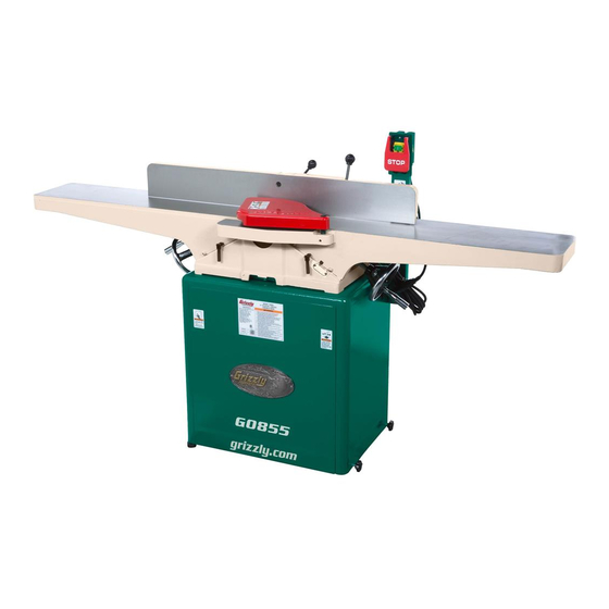
MODEL G0855/G0856
8" DOVETAIL JOINTER
w/MOBILE BASE
OWNER'S MANUAL
(For models manufactured since 02/19)
175370
COPYRIGHT © OCTOBER, 2018 BY GRIZZLY INDUSTRIAL, INC. REVISED JANUARY, 2019 (ES)
WARNING: NO PORTION OF THIS MANUAL MAY BE REPRODUCED IN ANY SHAPE
OR FORM WITHOUT THE WRITTEN APPROVAL OF GRIZZLY INDUSTRIAL, INC.
V2.01.19
#ES19680 PRINTED IN TAIWAN
Advertisement
Table of Contents

Related Manuals for Grizzly G0855


Summary of Contents for Grizzly G0855
- Page 1 (For models manufactured since 02/19) 175370 COPYRIGHT © OCTOBER, 2018 BY GRIZZLY INDUSTRIAL, INC. REVISED JANUARY, 2019 (ES) WARNING: NO PORTION OF THIS MANUAL MAY BE REPRODUCED IN ANY SHAPE OR FORM WITHOUT THE WRITTEN APPROVAL OF GRIZZLY INDUSTRIAL, INC.
- Page 2 This manual provides critical safety instructions on the proper setup, operation, maintenance, and service of this machine/tool. Save this document, refer to it often, and use it to instruct other operators. Failure to read, understand and follow the instructions in this manual may result in fire or serious personal injury—including amputation, electrocution, or death.
-
Page 3: Table Of Contents
Cleaning & Protecting ........38 Identification ........... 3 Lubrication ........... 39 Controls & Components ......... 4 Machine Data Sheet (G0855) ......6 SECTION 7: SERVICE ........40 Machine Data Sheet (G0856) ......8 Troubleshooting ........... 40 Setting/Replacing Knives (G0855) ....42 SECTION 1: SAFETY ........ -
Page 4: Introduction
Machine Differences and it helps us determine if updated documenta- tion is available for your machine. Models G0855 and G0856 are 3 HP, 8" x 72" joint- ers with the following differences: Model G0855 has a 4-knife cutterhead with •... -
Page 5: Identification
". d) Always use hold-down or push blocks when jointing material narrower than 3" or planing material thinner than 3". e) Never perform jointing, planing, or rabbeting cuts on pieces shorter than 10" in length. Model G0855/G0856 (Mfd. Since 02/19) -
Page 6: Controls & Components
H. Outfeed Table Adjustment Handwheel: included). Rotate to adjust position of outfeed table (when outfeed table lock is loosened). Only B. STOP Paddle: Push to stop motor. used when setting outfeed table even with cutterhead knives/inserts. Model G0855/G0856 (Mfd. Since 02/19) - Page 7 ". Infeed table stop automatically sets depth of cut at ⁄ ". N. Infeed Depth Stop: Use to adjust infeed table between finish/final cuts and shaping/ heavy cuts. Also limits movement range of infeed table. Model G0855/G0856 (Mfd. Since 02/19)
-
Page 8: Machine Data Sheet (G0855)
Machine Data Sheet (G0855) MACHINE DATA SHEET Customer Service #: (570) 546-9663 · To Order Call: (800) 523-4777 · Fax #: (800) 438-5901 MODEL G0855 8" X 72" DOVETAIL JOINTER WITH BUILT‐IN MOBILE BASE Product Dimensions: Weight................................335 lbs. Width (side-to-side) x Depth (front-to-back) x Height............... 72-1/2 x 25-1/2 x 42 in. - Page 9 The information contained herein is deemed accurate as of 12/7/2018 and represents our most recent product specifications. Model G0855 PAGE 2 OF 3 Due to our ongoing improvement efforts, this information may not accurately describe items previously purchased. Model G0855/G0856 (Mfd. Since 02/19)
-
Page 10: Machine Data Sheet (G0856)
The information contained herein is deemed accurate as of 12/7/2018 and represents our most recent product specifications. Model G0856 PAGE 1 OF 3 Due to our ongoing improvement efforts, this information may not accurately describe items previously purchased. Model G0855/G0856 (Mfd. Since 02/19) - Page 11 The information contained herein is deemed accurate as of 12/7/2018 and represents our most recent product specifications. Model G0856 PAGE 2 OF 3 Due to our ongoing improvement efforts, this information may not accurately describe items previously purchased. Model G0855/G0856 (Mfd. Since 02/19)
-
Page 12: Section 1: Safety
Never operate under the influence of drugs or injury or blindness from flying particles. Everyday alcohol, when tired, or when distracted. eyeglasses are NOT approved safety glasses. -10- Model G0855/G0856 (Mfd. Since 02/19) - Page 13 Make sure they are properly installed, you experience difficulties performing the intend- undamaged, and working correctly BEFORE ed operation, stop using the machine! Contact our operating machine. Technical Support at (570) 546-9663. -11- Model G0855/G0856 (Mfd. Since 02/19)
-
Page 14: Additional Safety For Jointers
Straight knives should never project MAXIMUM CUTTING DEPTH. To reduce risk of more than ⁄ " (0.125") from cutterhead body. kickback, never cut deeper than ⁄ " per pass. -12- Model G0855/G0856 (Mfd. Since 02/19) -
Page 15: Section 2: Power Supply
To reduce the risk of these hazards, avoid over- loading the machine during operation and make sure it is connected to a power supply circuit that meets the specified circuit requirements. -13- Model G0855/G0856 (Mfd. Since 02/19) - Page 16 Minimum Gauge Size ......12 AWG all local codes and ordinances. Maximum Length (Shorter is Better)..50 ft. -14- Model G0855/G0856 (Mfd. Since 02/19)
-
Page 17: Section 3: Setup
IMPORTANT: Save all packaging materials until Keep children and pets away you are completely satisfied with the machine and from plastic bags or packing have resolved any issues between Grizzly or the materials shipped with this shipping agent. You MUST have the original pack- machine. -
Page 18: Inventory
—T-Handle Torx Driver T-25 ....2 —Torx Screws T-25 #10-32 x ⁄ " ..10 —Indexable Inserts 15 x 15 x 2.5mm ..5 Figure 7. Inventory—wood crate. Figure 8. Inventory—cardboard box. Figure 9. Inventory—loose items. -16- Model G0855/G0856 (Mfd. Since 02/19) -
Page 19: Hardware Recognition Chart
Hardware Recognition Chart USE THIS CHART TO MATCH UP HARDWARE DURING THE INVENTORY AND ASSEMBLY PROCESS. Flat Head Screw -17- Model G0855/G0856 (Mfd. Since 02/19) -
Page 20: Cleanup
Figure 10. T23692 Orange Power Degreaser. Repeat Steps 2–3 as necessary until clean, then coat all unpainted surfaces with a quality metal protectant to prevent rust. -18- Model G0855/G0856 (Mfd. Since 02/19) -
Page 21: Site Considerations
Only install in an Shadows, glare, or strobe effects that may distract access restricted location. or impede the operator must be eliminated. Wall Min. 30" for Maintenance " " Figure 11. Minimum working clearances. -19- Model G0855/G0856 (Mfd. Since 02/19) -
Page 22: Assembly
Test Run. To assemble jointer: Open cardboard box and place stand upright. Tighten mobile base lock knobs (see Figure 2 on Page 4) to secure stand in position. -20- Model G0855/G0856 (Mfd. Since 02/19) - Page 23 Pulley Figure 13. Table assembly secured to stand. Adjust feet (see Figure 14) as necessary until jointer is stable without any rocking or Figure 15. V-belt installed. wobbling. Adjustable Feet Figure 14. Leveling jointer. -21- Model G0855/G0856 (Mfd. Since 02/19)
- Page 24 (Use straightedge if needed.) 13. Tighten set screws and repeat Step 10 to ver- ify proper pulley alignment. Pulleys should be parallel and aligned, as shown in Figure 17, when belt is properly tensioned. -22- Model G0855/G0856 (Mfd. Since 02/19)
- Page 25 Figure 19. Switch pedestal attached to stand and cords connected. 19. Install dust port with (4) ⁄ "-20 x ⁄ " Phillips head screws and (4) ⁄ " flat washers (see Figure 20). Figure 20. Dust port installed. -23- Model G0855/G0856 (Mfd. Since 02/19)
-
Page 26: Knife-Setting Jig (G0855)
— If cutterhead guard does not spring back over cutterhead and contact fence, or if it drags across outfeed table, then it must be adjusted (refer to Checking/Adjusting Cutterhead Guard on Page 54 for instructions). -24- Model G0855/G0856 (Mfd. Since 02/19) -
Page 27: Dust Collection
Figure 24. Example of dust hose attached to dust port. Push STOP paddle to stop machine. Congratulations! The Test Run is complete. Tug hose to make sure it does not come off. A tight fit is necessary for proper performance. -25- Model G0855/G0856 (Mfd. Since 02/19) -
Page 28: Tightening Belt
Use padlocks with a maximum shaft diameter of 4mm. With any padlock used to lock the switch, test the switch after installation to ensure that it is properly disabled. -26- Model G0855/G0856 (Mfd. Since 02/19) -
Page 29: Section 4: Operations
Read books/magazines or get formal training before beginning any proj- ects. Regardless of the content in this sec- tion, Grizzly Industrial will not be held liable for accidents caused by lack of training. -27- Model G0855/G0856 (Mfd. Since 02/19) -
Page 30: Stock Inspection & Requirements
Cutting " Min. these may lead to injury or machine damage. Figure 27. Minimum stock dimensions for jointer. -28- Model G0855/G0856 (Mfd. Since 02/19) 10" Min. -
Page 31: Squaring Stock
Rip Cut on a Table Saw—Jointed edge Surface Plane on Jointer—Concave face of of workpiece is placed against a table saw workpiece is surface planed flat with jointer. fence and opposite edge cut off. Previously Jointed Edge -29- Model G0855/G0856 (Mfd. Since 02/19) -
Page 32: Surface Planing
Tip: When squaring up stock, cut opposite side of workpiece with a planer instead of the Removed jointer to ensure boths sides are parallel. Surface Figure 28. Example photo of a surface planing operation. -30- Model G0855/G0856 (Mfd. Since 02/19) -
Page 33: Edge Jointing
Tip: When squaring up stock, cut opposite Figure 29. Example photo of an edge jointing edge of workpiece with a table saw instead operation. of the jointer—otherwise, both edges of work- piece will not be parallel with each other. -31- Model G0855/G0856 (Mfd. Since 02/19) -
Page 34: Bevel Cutting
4" from moving cutterhead at any time during operation! Removed Repeat cutting process, as necessary, until Surface you are satisfied with the results. Figure 30. Example of fence set up for a bevel cut of 45°. -32- Model G0855/G0856 (Mfd. Since 02/19) -
Page 35: Rabbet Cutting
To minimize risk of injury and unnec- essary exposure to cutterhead, always keep cutterhead guard installed when pos- sible, and ALWAYS immediately replace it after performing rabbet cuts. -33- Model G0855/G0856 (Mfd. Since 02/19) -
Page 36: Setting Depth Of Cut
Re-install cutterhead guard if removed in table handwheel to raise or lower the table, and Step 3. then tighten the lock to secure the setting. Infeed Table Lock Infeed Table Handwheel Figure 32. Infeed table height controls. -34- Model G0855/G0856 (Mfd. Since 02/19) - Page 37 (or less) when rabbeting. Note: If you need to lower the infeed table ⁄ ", then pull and hold the ⁄ " depth more than stop release knob (see Figure 35) while low- ering infeed table. -35- Model G0855/G0856 (Mfd. Since 02/19)
-
Page 38: Section 5: Accessories
SECTION 5: ACCESSORIES Accessories H7654—8" Indexable Spiral Cutterhead These cutterheads replace the standard straight- knife cutterheads on our Grizzly jointers and Installing unapproved accessories may planers. Each cutterhead has four spirals with cause machine to malfunction, resulting in indexable, four-sided carbide inserts that can be serious personal injury or machine damage. - Page 39 This handy tool sharpens flat and beveled sur- faces quickly and easily. Great for touch-ups. T20503 T20452 T20451 T20456 Figure 43. Assortment of basic eye protection. Figure 41. Jointer knife hone. www.grizzly.com 1-800-523-4777 order online at or call -37- Model G0855/G0856 (Mfd. Since 02/19)
-
Page 40: Section 6: Maintenance
Clean/vacuum dust buildup from inside stand and off of motor. TT27914—Moly-D Machine & Way Oil ISO 68 Figure 45. Recommended products for protecting unpainted cast-iron and steel. Figure 44. T27914 Moly-D Machine & Way Oil. -38- Model G0855/G0856 (Mfd. Since 02/19) -
Page 41: Lubrication
Lubrication Leadscrews Oil Type ..Grizzly T27914 or ISO 68 Equivalent Oil Amount ...........1–2 Drops Lubrication Frequency ....... Monthly, or As Needed Since all bearings are sealed and permanently lubricated, simply leave them alone until they Clean leadscrews (see Figure 47) with mineral need to be replaced. -
Page 42: Section 7: Service
6. Sharpen/replace knives (Page 43); rotate/replace 6. Dull knives/inserts. inserts (Page 45). 7. Cutterhead bearings at fault. 7. Replace bearing(s). 8. Centrifugal switch at fault. 8. Adjust/replace centrifugal switch if available. 9. Motor bearings at fault. 9. Test/repair/replace. -40- Model G0855/G0856 (Mfd. Since 02/19) - Page 43 1. Align outfeed table with cutterhead knife/insert at (gouge in end of top dead center (Page 48). board that is uneven 2. Knives set too high (G0855). 2. Adjust height of knives evenly with outfeed table with rest of cut). (Page 43).
-
Page 44: Setting/Replacing Knives (G0855)
— If knives do not touch straightedge or they Open-End Wrench 10mm ........1 lift up at any position, then those knives need to be adjusted (refer to Setting/ Replacing Knives on Page 43). -42- Model G0855/G0856 (Mfd. Since 02/19) - Page 45 Rotate cutterhead pulley to provide good access to cutterhead knives. DISCONNECT MACHINE FROM POWER! Remove cutterhead guard or block it open. Lower infeed table to ⁄ " scale mark. Place knife jig on cutterhead, directly over a knife. -43- Model G0855/G0856 (Mfd. Since 02/19)
- Page 46 Tighten each gib bolt in the same alternating manner as you did in the previous step. 10. Make sure outfeed table is set even with the new knives at top dead center. 11. Replace cutterhead guard and cabinet rear access panel. -44- Model G0855/G0856 (Mfd. Since 02/19)
-
Page 47: Rotating/Replacing Spiral Cutterhead Inserts (G0856)
Figure . Insert rotating sequence. Torx screws. Item(s) Needed Carbide Inserts 15 x 15 x 2.5mm ..As Needed Torx Head Screws T-25 #10-32 x ⁄ " As Needed Torque Wrench ..........1 T-25 Torx Bit ............1 -45- Model G0855/G0856 (Mfd. Since 02/19) -
Page 48: Adjusting Gibs
Note: Tighter gibs reduce play but make it harder to adjust tables. Set outfeed table height (refer to Setting Outfeed Table Height on Page 48). -46- Model G0855/G0856 (Mfd. Since 02/19) -
Page 49: Checking/Adjusting Table Parallelism
Figure 62. Locations to place shims when Straightedge adjusting table parallelism. Outfeed Infeed Re-check outfeed table height (refer to Setting Outfeed Table Height on Page 48), and re-adjust if necessary. Figure 60. Checking table parallelism. -47- Model G0855/G0856 (Mfd. Since 02/19) -
Page 50: Setting Outfeed Table Height
Figure 64. Knife or insert at TDC. Remove cutterhead guard and fence, then open belt cover. G0855 Straightedge G0855 Only: Make sure knife heights are set correctly (refer to Setting/Replacing Knives Outfeed Infeed on Page 43). Loosen outfeed table lock (see Figure 63). -
Page 51: Setting Fence Stops
90° while cap screw is resting on stop block (see Figure 68). Verify angle, then retighten jam Figure 67. Example of adjusting fence to 45° nut. inward. -49- Model G0855/G0856 (Mfd. Since 02/19) - Page 52 Figure 70. Fence set to 45° outward. Loosen jam nut on 45° stop bolt and adjust stop bolt until fence is exactly 45° outward while resting on stop bolt (see Figure 70). Verify angle, then retighten jam nut. -50- Model G0855/G0856 (Mfd. Since 02/19)
-
Page 53: Calibrating Depth-Of-Cut Scale
Loosen Phillips head screw, adjust scale pointer to point to "0", then re-tighten screw. (see Figure 73). Phillips Head Screw Scale Pointer "0" Scale Figure 73. Depth-of-cut scale set to "0". -51- Model G0855/G0856 (Mfd. Since 02/19) -
Page 54: Tensioning/Replacing V-Belt
(3 of 4 shown). dure to set correct belt tension. Press down on motor to keep tension on belt. Tighten motor mount fasteners (see Figure 74), replace rear access panel, and close belt cover. -52- Model G0855/G0856 (Mfd. Since 02/19) -
Page 55: Checking/Aligning Pulleys
Figure 77, when belt is properly pulley faces to check alignment. tensioned. Re-install fence, belt cover, and rear access panel on stand Cutterhead Belt Pulley Motor Pulley Figure 76. Checking pulley alignment (viewed from above). -53- Model G0855/G0856 (Mfd. Since 02/19) -
Page 56: Checking/Adjusting Cutterhead Guard
— If cutterhead guard does not spring back over cutterhead, does not contact fence, or drags across outfeed table, then pro- ceed to Step 3. -54- Model G0855/G0856 (Mfd. Since 02/19) -
Page 57: Section 8: Wiring
Technical Support at (570) 546-9663. The photos and diagrams included in this section are best viewed in color. You can view these pages in color at www.grizzly.com. -55- Model G0855/G0856 (Mfd. Since 02/19) -
Page 58: Wiring Diagram
SHOCK HAZARD! Disconnect power before working on wiring. Ground Ground Ground Motor 6-20 Plug Motor Junction Box Figure 79. On/Stop switch connections. Figure 80. Motor junction box connections. READ ELECTRICAL SAFETY -56- Model G0855/G0856 (Mfd. Since 02/19) ON PAGE 55! -
Page 59: Section 9: Parts
SECTION 9: PARTS Fence & Cutterhead (G0855 Only) (G0856 Only) 40-2 40-3 (G0856 Only) 40-6 40-5 40-4 40-3 40-2 (G0855 Only) BUY PARTS ONLINE AT GRIZZLY.COM! -57- Model G0855/G0856 (Mfd. Since 02/19) Scan QR code to visit our Parts Store. -
Page 60: Tables, Base, Stand & Motor
101 110 86-15 86-10 86-16 86-11 86-16 86-12 86-17 86-13 86-14 86-18 85V2 86-5 86-4 86-3 86-6 86-2 86-9 86-7 86-8 BUY PARTS ONLINE AT GRIZZLY.COM! -58- Model G0855/G0856 (Mfd. Since 02/19) Scan QR code to visit our Parts Store. - Page 61 P0855087 WHEEL AXLE 3/8-16 X 1-3/16, 2-1/2L P0855048 HEX NUT 1/4-20 P0855088 WHEEL P0855049 DEPTH STOP BLOCK P0855089 LOCK NUT 3/8-16 BUY PARTS ONLINE AT GRIZZLY.COM! -59- Model G0855/G0856 (Mfd. Since 02/19) Scan QR code to visit our Parts Store.
- Page 62 P0856111 TORX DRIVER T-25 (G0856) P0855136 HEX WRENCH 6MM P0855112 GUARD PIVOT SHAFT P0855137 GROUND LABEL P0855113 EXT RETAINING RING 11MM BUY PARTS ONLINE AT GRIZZLY.COM! -60- Model G0855/G0856 (Mfd. Since 02/19) Scan QR code to visit our Parts Store.
-
Page 63: Labels & Cosmetics
Safety labels help reduce the risk of serious injury caused by machine hazards. If any label comes off or becomes unreadable, the owner of this machine MUST replace it in the original location before resuming operations. For replacements, contact (800) 523-4777 or www.grizzly.com. BUY PARTS ONLINE AT GRIZZLY.COM! -61- Model G0855/G0856 (Mfd. - Page 65 Would you recommend Grizzly Industrial to a friend? _____ Yes _____No Would you allow us to use your name as a reference for Grizzly customers in your area? Note: We never use names more than 3 times. _____ Yes _____No 10.
- Page 66 FOLD ALONG DOTTED LINE Place Stamp Here GRIZZLY INDUSTRIAL, INC. P.O. BOX 2069 BELLINGHAM, WA 98227-2069 FOLD ALONG DOTTED LINE Send a Grizzly Catalog to a friend: Name_______________________________ Street_______________________________ City______________State______Zip______ TAPE ALONG EDGES--PLEASE DO NOT STAPLE...
-
Page 67: Warranty & Returns
WARRANTY & RETURNS Grizzly Industrial, Inc. warrants every product it sells for a period of 1 year to the original purchaser from the date of purchase. This warranty does not apply to defects due directly or indirectly to misuse, abuse, negligence, accidents, repairs or alterations or lack of maintenance.