Siemens SINUMERIK 840D sl Operating Manual
Hide thumbs
Also See for SINUMERIK 840D sl:
- Function manual (2184 pages) ,
- Programming manual (1334 pages) ,
- Commissioning manual (1102 pages)
Table of Contents
Advertisement
Quick Links
SINUMERIK
SINUMERIK 840D sl/828D
Universal
Operating Manual
Valid for:
SINUMERIK 840D sl / 840DE sl / 828D
Software
CNC system software for 840D sl/ 840DE sl V4.8 SP1
SINUMERIK Operate for PCU/PC
05/2017
A5E40868517
Preface
Fundamental safety
instructions
Introduction
Operating with gestures
Setting up the machine
Working in manual mode
Machining the workpiece
Simulating machining
Creating a G code program
Multi-channel view
Collision avoidance (only
840D sl)
Tool management
Managing programs
Teaching in a program
HT 8
Widescreen format multi-
touch panels (840D sl only)
Ctrl-Energy
Easy Message (828D only)
Easy Extend (828D only)
Service Planner (828D only)
Edit PLC user program (828D
Version
only)
V4.8 SP1
Alarm, error, and system
messages
Appendix
1
2
3
4
5
6
7
8
9
10
11
12
13
14
15
16
17
18
19
20
21
A
Advertisement
Table of Contents

Related Manuals for Siemens SINUMERIK 840D sl


Summary of Contents for Siemens SINUMERIK 840D sl
- Page 1 Widescreen format multi- touch panels (840D sl only) Ctrl-Energy Easy Message (828D only) Easy Extend (828D only) Valid for: SINUMERIK 840D sl / 840DE sl / 828D Service Planner (828D only) Edit PLC user program (828D Software Version only) CNC system software for 840D sl/ 840DE sl V4.8 SP1 SINUMERIK Operate for PCU/PC V4.8 SP1...
- Page 2 Note the following: WARNING Siemens products may only be used for the applications described in the catalog and in the relevant technical documentation. If products and components from other manufacturers are used, these must be recommended or approved by Siemens. Proper transport, storage, installation, assembly, commissioning, operation and maintenance are required to ensure that the products operate safely and without any problems.
-
Page 3: Preface
Siemens' content, and adapt it for your own machine documentation. Training At the following address (http://www.siemens.com/sitrain), you can find information about SITRAIN (Siemens training on products, systems and solutions for automation and drives). FAQs You can find Frequently Asked Questions in the Service&Support pages under Product Support (https://support.industry.siemens.com/cs/de/en/ps/faq). - Page 4 Technical Support Country-specific telephone numbers for technical support are provided in the Internet at the following address (https://support.industry.siemens.com/sc/ww/en/sc/2090) in the "Contact" area. Universal Operating Manual, 05/2017, A5E40868517...
- Page 5 Table of contents Preface.................................3 Fundamental safety instructions.........................15 General safety instructions.....................15 Industrial security........................16 Introduction..............................17 Product overview........................17 Operator panel fronts......................18 2.2.1 Overview..........................18 2.2.2 Keys of the operator panel.....................20 Machine control panels......................27 2.3.1 Overview..........................27 2.3.2 Controls on the machine control panel...................27 Operator interface........................31 2.4.1 Screen layout.........................31 2.4.2...
- Page 6 Table of contents Modes of operation........................66 4.3.1 General information........................66 4.3.2 Modes groups and channels....................68 4.3.3 Channel switchover........................68 Settings for the machine......................69 4.4.1 Switching over the coordinate system (MCS/WCS)...............69 4.4.2 Switching the unit of measurement..................70 4.4.3 Setting the zero offset......................71 Zero offsets..........................73 4.5.1 Display active zero offset.......................74 4.5.2...
- Page 7 Table of contents 6.4.1 Current block display......................102 6.4.2 Displaying a basic block ......................104 6.4.3 Display program level......................104 Correcting a program......................105 Repositioning axes.......................106 Starting execution at a specific point..................107 6.7.1 Use block search........................107 6.7.2 Continuing program from search target................109 6.7.3 Simple search target definition.....................110 6.7.4 Defining an interruption point as search target..............110 6.7.5...
- Page 8 Table of contents 6.17.2.1 Open a DXF file........................151 6.17.2.2 Cleaning a DXF file......................151 6.17.2.3 Enlarging or reducing the CAD drawing................152 6.17.2.4 Changing the section......................152 6.17.2.5 Rotating the view........................153 6.17.2.6 Displaying/editing information for the geometric data............154 6.17.3 Importing and editing a DXF file...................154 6.17.3.1 General procedure.......................154 6.17.3.2...
- Page 9 Table of contents Creating a G code program........................189 Graphical programming......................189 Program views........................189 Program structure........................193 Fundamentals........................194 8.4.1 Machining planes.........................194 8.4.2 Current planes in cycles and input screens.................194 8.4.3 Programming a tool (T)......................195 Generating a G code program.....................195 Blank input...........................196 8.6.1 Overview..........................196 8.6.2 Calling the input screen......................197 8.6.3...
- Page 10 Table of contents 11.8.1 Position magazine........................239 11.8.2 Relocating a tool........................240 11.8.3 Deleting / unloading / loading / relocating all tools...............241 11.9 Tool details...........................242 11.9.1 Displaying tool details......................242 11.9.2 Cutting edge data.........................243 11.9.3 Tool data..........................245 11.9.4 Monitoring data........................245 11.10 Changing a tool type......................246 11.11 Sorting tool management lists....................247 11.12...
- Page 11 Table of contents 12.10 Deleting a directory/program....................281 12.11 Changing file and directory properties.................282 12.12 Set up drives........................283 12.12.1 Overview..........................283 12.12.2 Setting up drives........................284 12.13 Viewing PDF documents......................290 12.14 EXTCALL..........................291 12.15 Execution from external memory (EES)................294 12.16 Backing up data........................294 12.16.1 Generating an archive in the Program Manager..............294 12.16.2 Generating an archive via the system data................295...
- Page 12 Table of contents Widescreen format multi-touch panels (840D sl only)................331 15.1 Sidescreen with standard windows..................332 15.2 Sidescreen with windows for the ABC keyboard and/or machine control panel....334 Ctrl-Energy...............................337 16.1 Functions..........................337 16.2 Ctrl-E analysis........................338 16.2.1 Displaying energy consumption...................338 16.2.2 Displaying the energy analyses...................339 16.2.3 Measuring and saving the energy consumption..............340 16.2.4...
- Page 13 Table of contents 20.5 View of the program blocks....................368 20.5.1 Displaying information on the program blocks..............368 20.5.2 Structure of the user interface....................369 20.5.3 Control options........................370 20.5.4 Displaying the program status....................371 20.5.5 Changing the address display....................372 20.5.6 Enlarging/reducing the ladder diagram................373 20.5.7 Program block........................373 20.5.7.1...
- Page 14 Table of contents Appendix..............................407 840D sl / 828D documentation overview................407 Index.................................409 Universal Operating Manual, 05/2017, A5E40868517...
-
Page 15: Fundamental Safety Instructions
Fundamental safety instructions General safety instructions WARNING Danger to life if the safety instructions and residual risks are not observed If the safety instructions and residual risks in the associated hardware documentation are not observed, accidents involving severe injuries or death can occur. ●... -
Page 16: Industrial Security
Siemens’ products and solutions undergo continuous development to make them more secure. Siemens strongly recommends to apply product updates as soon as available and to always use the latest product versions. Use of product versions that are no longer supported, and failure to apply latest updates may increase customer’s exposure to cyber threats. -
Page 17: Introduction
Introduction Product overview The SINUMERIK controller is a CNC (Computerized Numerical Controller) for machine tools. You can use the CNC to implement the following basic functions in conjunction with a machine tool: ● Creation and adaptation of part programs ● Execution of part programs ●... -
Page 18: Operator Panel Fronts
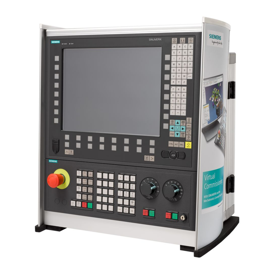
Introduction 2.2 Operator panel fronts Operator panel fronts 2.2.1 Overview Introduction The display (screen) and operation (e.g. hardkeys and softkeys) of the SINUMERIK Operate user interface use the operator panel front. In this example, the OP 010 operator panel front is used to illustrate the components that are available for operating the controller and machine tool. - Page 19 Introduction 2.2 Operator panel fronts Operator controls and indicators Alphabetic key group With the <Shift> key pressed, you activate the special characters on keys with double assign‐ ments, and write in the uppercase. Note: Depending on the particular configuration of your control system, uppercase letters are always written Numerical key group With the <Shift>...
-
Page 20: Keys Of The Operator Panel
Introduction 2.2 Operator panel fronts Manual operator components and networking; SINUMERIK 840D sl 2.2.2 Keys of the operator panel The following keys and key combinations are available for operation of the control and the machine tool. Keys and key combinations Function <ALARM CANCEL>... - Page 21 Introduction 2.2 Operator panel fronts <NEXT WINDOW> + <CTRL> + <SHIFT> ● Moves the cursor to the beginning of a program. ● Moves the cursor to the first row of the current column. ● Selects a contiguous selection from the current cursor position up to the target position.
- Page 22 Introduction 2.2 Operator panel fronts <Cursor up> ● Editing box Moves the cursor into the next upper field. ● Navigation – Moves the cursor in a table to the next cell upwards. – Moves the cursor upwards in a menu screen. <Cursor up>...
- Page 23 Introduction 2.2 Operator panel fronts <END> + <SHIFT> Moves the cursor to the last entry. Selects a contiguous selection from the cursor position up to the end of a program block. <END> + <CTRL> Moves the cursor to the last entry in the last line of the actual column or to the end of a program.
-
Page 24: Ctrl-Energy
Introduction 2.2 Operator panel fronts <CTRL> + <E> Calls the "Ctrl Energy" function. <CTRL> + <F> Opens the search dialog in the machine data and setting data lists, when loading and saving in the MDI editor as well as in the program manager and in the system data. - Page 25 Introduction 2.2 Operator panel fronts <CTRL> + <ALT> + <S> Creates a complete standard archive (.ARC) on an external data carrier (USB-FlashDrive) (for 840D sl). Creates a complete Easy Archive (.ARD) on an external data carrier (USB-FlashDrive) (for 828D). Note: The complete backup (.ARC) via this key combination is only suita‐...
- Page 26 Introduction 2.2 Operator panel fronts <Plus> ● Opens a directory which contains the element. ● Increases the size of the graphic view for simulation and traces. <Minus> ● Closes a directory which contains the element. ● Reduces the size of the graphic view for simulation and traces. <Equals>...
-
Page 27: Machine Control Panels
2.3.1 Overview The machine tool can be equipped with a machine control panel by Siemens or with a specific machine control panel from the machine manufacturer. You use the machine control panel to initiate actions on the machine tool such as traversing an axis or starting the machining of a workpiece. - Page 28 Introduction 2.3 Machine control panels Overview EMERGENCY STOP button Installation locations for control devices (d = 16 mm) RESET Program control Operating modes, machine functions User keys T1 to T15 Traversing axes with rapid traverse override and coordinate switchover Spindle control with override switch Feed control with override switch (10) Keyswitch (four positions)
- Page 29 Introduction 2.3 Machine control panels Program control <SINGLE BLOCK> Single block mode on/off. <CYCLE START> The key is also referred to as NC Start. Execution of a program is started. <CYCLE STOP> The key is also referred to as NC Stop. Execution of a program is stopped.
- Page 30 Introduction 2.3 Machine control panels Traversing axes with rapid traverse override and coordinate switchover Axis keys Selects an axis. Direction keys Select the traversing direction. <RAPID> Traverse axis in rapid traverse while pressing the direction key. <WCS MCS> Switches between the workpiece coordinate system (WCS) and machine coordinate system (MCS).
-
Page 31: Operator Interface
Introduction 2.4 Operator interface Operator interface 2.4.1 Screen layout Overview Active operating area and mode Alarm/message line Channel operational messages Display for ● Active tool T ● Current feedrate F ● Active spindle with current status (S) ● Spindle utilization rate in percent ●... -
Page 32: Status Display
The machine is feeding energy back into the grid. The power rating display must be switched on in the status line. Note Information about configuration is available in the following reference: System Manual "Ctrl-Energy", SINUMERIK 840D sl / 828D Universal Operating Manual, 05/2017, A5E40868517... - Page 33 Introduction 2.4 Operator interface Active operating area Display Description "Machine" operating area With touch operation, you can change the operating area here. "Parameter" operating area "Program" operating area "Program manager" operating area "Diagnosis" operating area "Start-up" operating area Active mode or submode Display Description "Jog"...
-
Page 34: Actual Value Window
Introduction 2.4 Operator interface Second line Display Description Program path and program name The displays in the second line can be configured. Machine manufacturer Please refer to the machine manufacturer's specifications. Third line Display Description Display of channel status. If several channels are present on the machine, the channel name is also displayed. - Page 35 Introduction 2.4 Operator interface Work/Machine The displayed coordinates are based on either the machine coordinate system or the workpiece coordinate system. The machine coordinate system (Machine), in contrast to the workpiece coordinate system (Work), does not take any work offsets into consideration. You can use the "Machine actual values"...
-
Page 36: T,F,S Window
Introduction 2.4 Operator interface Display Meaning Collision monitoring Collision avoidance is activated for the JOG and MDA or (only 840D sl) AUTOMATIC modes. Note: The $MN_JOG_MODE_MASK machine data can be set to suppress the display of the symbol. Please refer to the machine manufacturer's specifications. Collision avoidance is deactivated for the JOG and MDA or AUTOMATIC modes. - Page 37 Introduction 2.4 Operator interface Display Meaning H number (tool offset data record for DIN-ISO mode) If there is a valid D number, this is also displayed. Ø Diameter of the current tool Radius of the current tool Length of the actual tool Z value of the current tool X value of the current tool Feed data...
-
Page 38: Current Block Display
Introduction 2.4 Operator interface Note Display of logical spindles If the spindle converter is active, logical spindles are displayed in the workpiece coordinate system. When switching over to the machine coordinate system, the physical spindles are displayed. Machine manufacturer Please refer to the machine manufacturer's specifications. 2.4.5 Current block display The window of the current block display shows the program blocks currently being executed. - Page 39 Introduction 2.4 Operator interface Highlighting of selected G code commands or keywords In the program editor settings, you can specify whether selected G code commands are to be highlighted in color. The following colors are used as standard: Display Meaning Blue font D, S, F, T, M and H functions Red font...
-
Page 40: Operation Via Softkeys And Buttons
Introduction 2.4 Operator interface 2.4.6 Operation via softkeys and buttons Operating areas/operating modes The user interface consists of different windows featuring eight horizontal and eight vertical softkeys. You operate the softkeys with the keys next to the softkey bars. You can display a new window or execute functions using the softkeys. The operating software is sub-divided into six operating areas (machine, parameter, program, program manager, diagnosis, startup) and five operating modes or submodes (JOG, MDA, AUTO, TEACH IN, REF POINT, REPOS). -
Page 41: Entering Or Selecting Parameters
Introduction 2.4 Operator interface When you have entered all the necessary parameters in the parameter screen form correctly, you can close the window and save the parameters using the "Accept" softkey. The values you entered are applied to a program. Use the "OK"... - Page 42 Introduction 2.4 Operator interface Select the required setting using the <Cursor down> and <Cursor up> keys. If required, enter a value in the associated input field. Press the <INPUT> key to complete the parameter input. Changing or calculating parameters If you only want to change individual characters in an input field rather than overwriting the entire entry, switch to insertion mode.
-
Page 43: Pocket Calculator
Introduction 2.4 Operator interface + <number> Enter "r" or "R" as well as the number x from which you would like to extract the root. + <number> Enter "s" or "S" as well as the number x for which you would like to gen‐ erate the square. -
Page 44: Context Menu
Introduction 2.4 Operator interface Press the <INPUT> key. The new value is calculated and displayed in the entry field of the calcu‐ lator. Press the "Accept" softkey. The calculated value is accepted and displayed in the entry field of the window. -
Page 45: Changing The User Interface Language
Introduction 2.4 Operator interface Operating area switchover You can display the operating area menu by touching the display symbol for the active operating area in the status display. Channel switchover You can switch over to the next channel by touching the channel display in the status display. -
Page 46: Entering Chinese Characters
Introduction 2.4 Operator interface Note Changing the language directly on the input screens You can switch between the user interface languages available on the controller directly on the user interface by pressing the key combination <CTRL + L>. 2.4.12 Entering Chinese characters 2.4.12.1 Function - input editor Using the input editor IME (input method editor), you can select Asian characters where you... - Page 47 Introduction 2.4 Operator interface Structure of the editor Figure 2-4 Example: Pinyin input Figure 2-5 Example: Zhuyin input Functions Pinyin input Entering Latin letters Editing the dictionary Dictionaries The simplified Chinese and traditional Chinese dictionaries that are supplied can be expanded: ●...
-
Page 48: Entering Asian Characters
Introduction 2.4 Operator interface 2.4.12.2 Entering Asian characters Precondition The control has been switched over to Chinese. Procedure Editing characters using the Pinyin method Open the screen form and position the cursor on the input field. Press the <Alt +S> keys. The editor is displayed. -
Page 49: Editing The Dictionary
Introduction 2.4 Operator interface Press the <BACKSPACE> softkey to delete entered phonetic notations. To select the associated character, press the <cursor right> or <cursor left> keys. Press the <input> key to enter the character. 2.4.12.3 Editing the dictionary Learning function of the input editor Requirement: The control has been switched over to Chinese. -
Page 50: Entering Korean Characters
Introduction 2.4 Operator interface The generated file should be saved in the UTF8 format under the name dictchs.txt (simplified Chinese) or dictcht.txt (traditional Chinese). Line structure: Pinyin phonetic spelling <TAB> Chinese characters <LF> Pinyin phonetic spelling <TAB> Chinese character1<TAB> Chinese character2 <TAB> … <LF>... - Page 51 Introduction 2.4 Operator interface Korean keyboard To enter Korean characters, you will need a keyboard with the keyboard assignment shown below. In terms of key layout, this keyboard is the equivalent of an English QWERTY keyboard and individual events must be grouped together to form syllables. Structure of the editor Functions Editing characters using a matrix...
- Page 52 Introduction 2.4 Operator interface Procedure Editing characters using the keyboard Open the screen form and position the cursor on the input field. Press the <Alt +S> keys. The editor is displayed. Switch to the "Keyboard - Matrix" selection box. Select the keyboard. Switch to the function selection box.
-
Page 53: Protection Levels
Introduction 2.4 Operator interface Press the <BACKSPACE> softkey to delete entered phonetic notations. Press the <input> key to enter the character into the input field. 2.4.14 Protection levels The input and modification of data in the control system is protected by passwords at sensitive places. -
Page 54: Online Help In Sinumerik Operate
Introduction 2.4 Operator interface Diagnostics operating area Protection level Keyswitch 3 (protection level 4) User (protection level 3) User (protection level 3) Manufacturer (protection level 1) User (protection level 3) Service (protection level 2) Start-up operating area Protection levels End user (protection level 3) Keyswitch 3 (protection level 4) - Page 55 Introduction 2.4 Operator interface ● Lists of the machine data ● Lists of the setting data ● Lists of the drive parameters ● List of all alarms Procedure Calling context-sensitive online help You are in an arbitrary window of an operating area. Press the <HELP>...
- Page 56 Introduction 2.4 Operator interface Press the <Follow reference> softkey or the <INPUT> key to display the help page for the selected topic. Press the "Current topic" softkey to return to the original help. Searching for a topic Press the "Search" softkey. The "Search in Help for: "...
- Page 57 Introduction 2.4 Operator interface Press the "Transfer to editor" softkey. The selected G function is taken into the program at the cursor position. Press the "Exit help" softkey again to close the help. Universal Operating Manual, 05/2017, A5E40868517...
- Page 58 Introduction 2.4 Operator interface Universal Operating Manual, 05/2017, A5E40868517...
-
Page 59: Operating With Gestures
Operating with gestures Touch-sensitive user interface Touch-sensitive user interface Do not wear thick gloves when operating the touch-sensitive glass user interface. Wear thin gloves made of cotton or gloves for touch-sensitive glass user interfaces with capacitive touch function. You will operate the touch-sensitive glass user interface on the Operator panel optimally with the following gloves. -
Page 60: Finger Gestures
Operating with gestures 3.2 Finger gestures Finger gestures Finger gestures ● Select window ● Select object (e.g. NC block) ● Activate entry field – Enter or overwrite value – Tap again to change the value Flick vertically with one finger ●... - Page 61 Operating with gestures 3.2 Finger gestures Spread ● Zoom-out graphic contents (e.g. simulation, mold making view) Pinch ● Zoom-in graphic contents (e.g. simulation, mold making view) Pan with one finger ● Move graphic contents (e.g. simulation, mold making view) ● Move list contents Pan with two fingers ●...
- Page 62 Operating with gestures 3.2 Finger gestures Note Flicking gestures with several fingers The gestures only function reliably if you hold the fingers sufficiently far apart. Fingers should be at least 1 cm apart. Universal Operating Manual, 05/2017, A5E40868517...
-
Page 63: Setting Up The Machine
Setting up the machine Switching on and switching off Startup When the control starts up, the main screen opens according to the operating mode specified by the machine manufacturer. In general, this is the main screen for the "REF POINT" submode. -
Page 64: Approaching A Reference Point
Setting up the machine 4.2 Approaching a reference point Approaching a reference point 4.2.1 Referencing axes Your machine tool can be equipped with an absolute or incremental path measuring system. An axis with incremental path measuring system must be referenced after the controller has been switched on –... -
Page 65: User Agreement
Setting up the machine 4.2 Approaching a reference point Press the <-> or <+> key. The selected axis moves to the reference point. If you have pressed the wrong direction key, the action is not accepted and the axes do not move. A symbol is shown next to the axis if it has been referenced. -
Page 66: Modes Of Operation
Setting up the machine 4.3 Modes of operation Press the "User enable" softkey. The "User Agreement" window opens. It shows a list of all machine axes with their current position and SI position. Position the cursor in the "Acknowledgement" field for the axis in ques‐ tion. - Page 67 Setting up the machine 4.3 Modes of operation Selecting "REF POINT" Press the <REF POINT> key. "REPOS" operating mode The "REPOS" operating mode is used for repositioning to a defined position. After a program interruption (e.g. to correct tool wear values) move the tool away from the contour in "JOG" mode.
-
Page 68: Modes Groups And Channels
Setting up the machine 4.3 Modes of operation Selecting "Teach In" Press the <TEACH IN> key. 4.3.2 Modes groups and channels Every channel behaves like an independent NC. A maximum of one part program can be processed per channel. ● Control with 1channel One mode group exists. -
Page 69: Settings For The Machine
Setting up the machine 4.4 Settings for the machine Changing the channel Press the <CHANNEL> key. The channel changes over to the next channel. - OR - If the channel menu is available, a softkey bar is displayed. The active channel is highlighted. -
Page 70: Switching The Unit Of Measurement
Setting up the machine 4.4 Settings for the machine Procedure Select the "Machine" operating area. Press the <JOG> or <AUTO> key. Press the "Act.vls. MCS" softkey. The machine coordinate system is selected. The title of the actual value window changes in the MCS. Machine manufacturer The softkey to changeover the coordinate system can be hidden. -
Page 71: Setting The Zero Offset
Setting up the machine 4.4 Settings for the machine Function Manual, Basic Functions; Speeds, Setpoint/Actual-Value System, Closed-Loop Control (G2), Section "Metric/inch dimension system" Procedure Select the mode <JOG> or <AUTO> in the "Machine" operating area. Press the menu forward key and the "Settings" softkey. A new vertical softkey bar appears. - Page 72 Setting up the machine 4.4 Settings for the machine Relative actual value Further, you also have the possibility of entering position values in the relative coordinate system. Note The new actual value is only displayed. The relative actual value has no effect on the axis positions and the active zero offset.
-
Page 73: Zero Offsets
Setting up the machine 4.5 Zero offsets Press the ">>", "REL act. vals" and "Set REL" softkeys to set position values in the relative coordinate system. Enter the new required position value for X, Y or Z directly in the actual value display (you can toggle between the axes with the cursor keys) and press the "Input"... -
Page 74: Display Active Zero Offset
Setting up the machine 4.5 Zero offsets Figure 4-1 Zero offsets When the machine zero is not identical to the workpiece zero, at least one offset (base offset or zero offset) exists in which the position of the workpiece zero is saved. Base offset The base offset is a zero offset that is always active. -
Page 75: Displaying The Zero Offset "Overview
Setting up the machine 4.5 Zero offsets The availability of the offsets depends on the setting. Machine manufacturer Please refer to the machine manufacturer's specifications. Procedure Select the "Parameter" operating area. Press the "Zero offset" softkey. The "Zero Offset - Active" window is opened. Note Further details on zero offsets If you would like to see further details about the specified offsets or if you would like to change... - Page 76 Setting up the machine 4.5 Zero offsets Work offsets Displays the handwheel axis offset. $AA_OFF overlay Displays the overlaid movement programmed with $AA_OFF. Basic reference Displays the additional work offsets programmed with $P_SETFRAME. Access to the system offsets is protected via a keyswitch. External WO frame Displays the additional work offsets programmed with $P_EXTFRAME.
-
Page 77: Displaying And Editing Base Zero Offset
Setting up the machine 4.5 Zero offsets 4.5.3 Displaying and editing base zero offset The defined channel-specific and global base offsets, divided into coarse and fine offsets, are displayed for all set-up axes in the "Zero offset - Base" window. Machine manufacturer Please refer to the machine manufacturer's specifications. -
Page 78: Displaying And Editing Details Of The Zero Offsets
Setting up the machine 4.5 Zero offsets Press the "G54 … G599" softkey. The "Work offset - G54 ... G599 [mm]" window opens. Note The labeling of the softkeys for the settable work offsets varies, i.e. the settable work offsets configured on the machine are displayed (examples: G54 …... - Page 79 Setting up the machine 4.5 Zero offsets ● SC sum correction ● Total length ● Radius / radius wear You can also change the display of the tool correction values between the Ma‐ chine Coordinate System and the Workpiece Coordinate System. Machine manufacturer Please refer to the machine manufacturer's specifications.
-
Page 80: Deleting A Zero Offset
Setting up the machine 4.5 Zero offsets These value changes are available in the part program immediately or after "Reset". Machine manufacturer Please refer to the machine manufacturer's specifications. Press the "Back" softkey to close the window. 4.5.6 Deleting a zero offset You have the option of deleting work offsets. -
Page 81: Monitoring Axis And Spindle Data
Setting up the machine 4.6 Monitoring axis and spindle data Monitoring axis and spindle data 4.6.1 Specify working area limitations Using the "Working area limitation" function you can limit the range within which a tool can traverse in all channel axes. This function allows you to set up protection zones in the working area that are inhibited for tool motion. -
Page 82: Displaying Setting Data Lists
Setting up the machine 4.7 Displaying setting data lists You can limit the spindle speeds in fields "Minimum" and "Maximum" within the limit values defined in the relevant machine data. Spindle speed limitation at constant cutting rate In field "Spindle speed limitation at G96", the programmed spindle speed limitation at constant cutting speed is displayed together with the permanently active limitations. -
Page 83: Handwheel Assignment
Setting up the machine 4.8 Handwheel assignment Procedure Select the "Parameter" operating area. Press the "Setting data" and "Data lists" softkeys. The "Setting Data Lists" window opens. Press the "Select data list" softkey and in the "View" list, select the re‐ quired list with setting data. - Page 84 Setting up the machine 4.8 Handwheel assignment Procedure Select the "Machine" operating area. Press the <JOG>, <AUTO> or <MDI> key. Press the menu forward key and the "Handwheel" softkey. The "Handwheel" window appears. A field for axis assignment will be offered for every connected handwheel. Position the cursor in the field next to the handwheel with which you wish to assign the axis (e.g.
-
Page 85: Loading An Mda Program From The Program Manager
Setting up the machine 4.9 MDA In "MDI" mode (Manual Data Input mode), you can enter G-code commands or standard cycles block-by-block and immediately execute them for setting up the machine. You have the option of loading an MDI program or a standard program with the standard cycles directly into the MDI buffer from the program manager;... -
Page 86: Saving An Mda Program
Setting up the machine 4.9 MDA 4.9.2 Saving an MDA program Procedure Select the "Machine" operating area. Press the <MDI> key. The MDI editor opens. Create the MDI program by entering the G-code commands using the operator's keyboard. Press the "Store MDI" softkey. The "Save from MDI: Select storage location"... -
Page 87: Editing/Executing A Mdi Program
Setting up the machine 4.9 MDA 4.9.3 Editing/executing a MDI program Procedure Select the "Machine" operating area. Press the <MDI> key. The MDI editor opens. Enter the desired G-code commands using the operator’s keyboard. - OR - Enter a standard cycle, e.g. CYCLE62 (). Editing G-code commands/program blocks Edit G-code commands directly in the "MDI"... -
Page 88: Deleting An Mda Program
Setting up the machine 4.9 MDA 4.9.4 Deleting an MDA program Precondition The MDA editor contains a program that you created in the MDI window or loaded from the program manager. Procedure Press the "Delete blocks" softkey. The program blocks displayed in the program window are deleted. Universal Operating Manual, 05/2017, A5E40868517... -
Page 89: General
Working in manual mode General Always use "JOG" mode when you want to set up the machine for the execution of a program or to carry out simple traversing movements on the machine: ● Synchronize the measuring system of the controller with the machine (reference point approach) ●... -
Page 90: Selecting A Tool
Working in manual mode 5.2 Selecting a tool and spindle Parameter Meaning Unit Sister tool number (1 - 99 for sister tool strategy) Spindle Spindle selection, identification with spindle number Spindle M function Spindle off: Spindle is stopped CCW rotation: Spindle rotates counterclockwise CW rotation: Spindle rotates clockwise Spindle positioning: Spindle is moved to the desired position. -
Page 91: Starting And Stopping A Spindle Manually
Working in manual mode 5.2 Selecting a tool and spindle Press the "Select tool” softkey. The tool selection window opens. Place the cursor on the desired tool and press the "OK" softkey. The tool is transferred to the "T, S, M... window" and displayed in the field of tool parameter "T". -
Page 92: Position Spindle
Working in manual mode 5.3 Traversing axes Note Changing the spindle speed If you enter the speed in the "Spindle" field while the spindle is rotating, the new speed is applied. 5.2.4 Position spindle Procedure Select the "JOG" operating mode. Press the "T, S, M"... -
Page 93: Traverse Axes By A Defined Increment
Working in manual mode 5.3 Traversing axes During a traverse initiated from the keyboard, the selected axis moves at the programmed setup feedrate. During an incremental traverse, the selected axis traverses a specified increment. Set the default feedrate Specify the feedrate to be used for axis traversal in the set-up, in the "Settings for Manual Operation"... -
Page 94: Traversing Axes By A Variable Increment
Working in manual mode 5.4 Positioning axes Note When the controller is switched on, the axes can be traversed right up to the limits of the machine as the reference points have not yet been approached and the axes referenced. Emergency limit switches might be triggered as a result. -
Page 95: Manual Retraction
Working in manual mode 5.5 Manual retraction The feedrate / rapid traverse override is active during traversing. Procedure If required, select a tool. Select the "JOG" operating mode. Press the "Positions" softkey. Specify the desired value for the feedrate F. - OR - Press the "Rapid traverse"... -
Page 96: Default Settings For Manual Mode
Working in manual mode 5.6 Default settings for manual mode Procedure <RESET> interrupts the power supply to the machine and any running part program. After a power supply interruption, switch on the controller. Select the JOG operating mode. Press the Menu forward key. Press the "Retract"... - Page 97 Working in manual mode 5.6 Default settings for manual mode Procedure Select the "Machine" operating area. Press the <JOG> key. Press the menu forward key and the "Settings" softkey. The "Settings for manual operation" window is opened. Universal Operating Manual, 05/2017, A5E40868517...
- Page 98 Working in manual mode 5.6 Default settings for manual mode Universal Operating Manual, 05/2017, A5E40868517...
-
Page 99: Starting And Stopping Machining
Machining the workpiece Starting and stopping machining During execution of a program, the workpiece is machined in accordance with the programming on the machine. After the program is started in automatic mode, workpiece machining is performed automatically. Preconditions The following requirements must be met before executing a program: ●... -
Page 100: Selecting A Program
Machining the workpiece 6.2 Selecting a program Stopping machining Press the <CYCLE STOP> key. Machining stops immediately, individual blocks do not finish execution. At the next start, execution is resumed at the same location where it stopped. Canceling machining Press the <RESET> key. Execution of the program is interrupted. -
Page 101: Program Running-In
Machining the workpiece 6.3 Program running-in Program running-in When testing a program, you can select that the system can interrupt the machining of the workpiece after each program block, which triggers a movement or auxiliary function on the machine. In this way, you can control the machining result block-by-block during the initial execution of a program on the machine. -
Page 102: Displaying The Current Program Block
Machining the workpiece 6.4 Displaying the current program block Press the <SINGLE BLOCK> key again, if the machining is not supposed to run block-by-block. The key is deselected again. If you now press the <CYCLE START> key again, the program is execu‐ ted to the end without interruption. - Page 103 Machining the workpiece 6.4 Displaying the current program block Highlighting of selected G code commands or keywords In the program editor settings, you can specify whether selected G code commands are to be highlighted in color. The following colors are used as standard: Display Meaning Blue font...
-
Page 104: Displaying A Basic Block
Machining the workpiece 6.4 Displaying the current program block 6.4.2 Displaying a basic block If you want precise information about axis positions and important G functions during testing or program execution, you can call up the basic block display. This is how you check, when using cycles, for example, whether the machine is actually traversing. -
Page 105: Correcting A Program
Machining the workpiece 6.5 Correcting a program Program example N10 subprogram P25 If, in at least one program level, a program is run through several times, a horizontal scroll bar is displayed that allows the run through counter P to be viewed in the righthand window section. The scroll bar disappears if multiple run-through is no longer applicable. -
Page 106: Repositioning Axes
Machining the workpiece 6.6 Repositioning axes Precondition A program must be selected for execution in "AUTO" mode. Procedure The program to be corrected is in the Stop or Reset mode. Press the "Prog. corr.” softkey. The program is opened in the editor. The program preprocessing and the current block are displayed. -
Page 107: Starting Execution At A Specific Point
Machining the workpiece 6.7 Starting execution at a specific point The feedrate/rapid traverse override is in effect. NOTICE Risk of collision When repositioning, the axes move with the programmed feedrate and linear interpolation, i.e. in a straight line from the current position to the interrupt point. Therefore, you must first move the axes to a safe position in order to avoid collisions. - Page 108 Machining the workpiece 6.7 Starting execution at a specific point Applications ● Stopping or interrupting program execution ● Specify a target position, e.g. during remachining Determining a search target ● User-friendly search target definition (search positions) – Direct specification of the search target by positioning the cursor in the selected program (main program) –...
-
Page 109: Continuing Program From Search Target
Machining the workpiece 6.7 Starting execution at a specific point Preconditions ● You have selected the desired program. ● The controller is in the reset state. ● The desired search mode is selected. NOTICE Risk of collision Pay attention to a collision-free start position and appropriate active tools and other technological values. -
Page 110: Simple Search Target Definition
Machining the workpiece 6.7 Starting execution at a specific point 6.7.3 Simple search target definition Requirement The program is selected and the controller is in Reset mode. Procedure Press the "Block search" softkey. Place the cursor on a particular program block. - OR - Press the "Find text"... -
Page 111: Entering The Search Target Via Search Pointer
Machining the workpiece 6.7 Starting execution at a specific point Procedure Press the "Block search" softkey. Press the "Interrupt point" softkey. The interruption point is loaded. If the "Higher level" and "Lower level" softkeys are available, use these to change the program level. Press the "Start search"... -
Page 112: Parameters For Block Search In The Search Pointer
Machining the workpiece 6.7 Starting execution at a specific point The specified target must always be unambiguous. This means, for example, that if the subprogram is called in the main program in two different places, you must also specify a target in program level 1 (main program). -
Page 113: Block Search Mode
Machining the workpiece 6.7 Starting execution at a specific point Parameter Meaning Type " " search target is ignored on this level N no. Block number Label Jump label Text string Subprg. Subprogram call Line Line number Search target Point in the program at which machining is to start 6.7.7 Block search mode Set the desired search variant in the "Search Mode"... - Page 114 Machining the workpiece 6.7 Starting execution at a specific point Block search mode Meaning Without calculation For a quick search in the main program. Calculations will not be performed during the block search, i.e. the calculation is skipped up to the target block. All settings required for execution have to be programmed from the target block (e.g.
-
Page 115: Controlling The Program Run
Machining the workpiece 6.8 Controlling the program run Controlling the program run 6.8.1 Program control You can change the program sequence in the "AUTO" and "MDA" modes. Abbreviation/program con‐ Mode of operation trol The program is started and executed with auxiliary function outputs and dwell times. In this mode, the axes are not traversed. -
Page 116: Skip Blocks
Machining the workpiece 6.8 Controlling the program run Activating program control You can control the program sequence however you wish by selecting and clearing the relevant checkboxes. Display / response of active program controls If program control is activated, the abbreviation of the corresponding function appears in the status display as feedback response. -
Page 117: Overstore
Machining the workpiece 6.9 Overstore Skip levels, activate Select the corresponding checkbox to activate the desired skip level. Note The "Program Control - Skip Blocks" window is only available when more than one skip level is set up. Overstore With overstore, you have the option of executing technological parameters (for example, auxiliary functions, axis feed, spindle speed, programmable instructions, etc.) before the program is actually started. -
Page 118: Editing A Program
Machining the workpiece 6.10 Editing a program Press the <CYCLE START> key. The blocks you have entered are stored. You can observe execution in the "Overstore" window. After the entered blocks have been executed, you can append blocks again. You cannot change the operating mode while you are in overstore mode. Press the "Back"... -
Page 119: Searching In Programs
Machining the workpiece 6.10 Editing a program Calling the editor ● The editor is started via the "Program correction" softkey in the "Machine" operating area. You can directly change the program by pressing the <INSERT> key. ● The editor is called via the "Open" softkey as well as with the <INPUT> or <Cursor right> key in the "Program manager"... - Page 120 Machining the workpiece 6.10 Editing a program Note Search with place holders When searching for specific program locations, you have the option of using place holders: ● "*": Replaces any character string ● "?": Replaces any character Precondition The desired program is opened in the editor. Procedure Press the "Search"...
-
Page 121: Replacing Program Text
Machining the workpiece 6.10 Editing a program 6.10.2 Replacing program text You can find and replace text in one step. Precondition The desired program is opened in the editor. Procedure Press the "Search" softkey. A new vertical softkey bar appears. Press the "Find and replace"... -
Page 122: Copying/Pasting/Deleting Program Blocks
Machining the workpiece 6.10 Editing a program See also Editor settings (Page 127) 6.10.3 Copying/pasting/deleting program blocks In the editor, you edit both basic G code as well as program steps such as cycles, blocks and subprogram calls. Inserting program blocks The editor responds depending on what type of program block you insert. -
Page 123: Renumbering A Program
Machining the workpiece 6.10 Editing a program Press the "Cut" softkey to delete the selected program blocks and to copy them into the buffer memory. Note: When editing a program, you cannot copy or cut more than 1024 lines. While a program that is not on the NC is opened (progress display less than 100%), you cannot copy or cut more than 10 lines or insert more than 1024 characters. -
Page 124: Creating A Program Block
Machining the workpiece 6.10 Editing a program Precondition The program is opened in the editor. Procedure Press the ">>" softkey. A new vertical softkey bar appears. Press the "Renumber" softkey. The "Renumbering" window appears. Enter the values for the first block number and the increment to be used for numbering. - Page 125 Machining the workpiece 6.10 Editing a program Display Meaning Addit. run-in code ● Yes For the case that the block is not executed, as the specified spindle should not be processed, then it is possible to temporarily activate a so-called "Addit.
-
Page 126: Opening Additional Programs
Machining the workpiece 6.10 Editing a program Note You can also open and close blocks with the mouse or using the cursor keys: ● <Cursor right> opens the block where the cursor is positioned ● <Cursor left> closes the block if the cursor is positioned at the beginning or end of the block ●... -
Page 127: Editor Settings
Machining the workpiece 6.10 Editing a program Procedure Press the ">>" and "Open additional program" softkeys. The "Select Additional Program" window is opened. Select the program or programs that you wish to display in addition to the already opened program. Press the "OK"... - Page 128 Machining the workpiece 6.10 Editing a program Setting Meaning Line break also in cycle ● Yes: If the line of a cycle call becomes too long, then it is displayed over calls several lines. ● No: The cycle call is truncated. The field is only visible if "Yes"...
- Page 129 Machining the workpiece 6.10 Editing a program Setting Meaning Highlight selected G Defines the display of G code commands. code commands ● No All G code commands are displayed in the standard color. ● Yes Selected G code commands or keywords are highlighted in color. Define the rules for the color assignment in the sleditorwidget.ini configuration file.
-
Page 130: Display And Edit User Variables
Machining the workpiece 6.11 Display and edit user variables Press the "Delete mach. times" softkey if you wish to delete the machining times. The machining times that have been determined are deleted from the editor as well as from the actual block display. If the machining times are saved to an ini file, then this file is also deleted. -
Page 131: Global R Parameters
You may search for user data within the lists using any character string. References You will find additional information in the following references: Programming Manual Job Planning / SINUMERIK 840D sl / 828D 6.11.2 Global R parameters Global R parameters are arithmetic parameters, which exist in the control itself, and can be read or written to by all channels. -
Page 132: R Parameters
Machining the workpiece 6.11 Display and edit user variables Procedure Select the "Parameter" operating area. Press the "User variable" softkey. Press the "Global R parameters" softkey. The "Global R parameters" window opens. Display comments Press the ">>" and "Display comments" softkeys. The "Global R parameters with comments "... - Page 133 Machining the workpiece 6.11 Display and edit user variables Comments You can save comments in the "R parameters with comments" window. These comments can be edited. You have the option of either individually deleting these comments, or using the delete function. These comments are retained after the control is switched off.
-
Page 134: Displaying Global User Data (Gud)
Machining the workpiece 6.11 Display and edit user variables Activate the checkbox "also delete comments" if the associated com‐ ments should also be automatically deleted. Press the "OK" softkey. ● A value of 0 is assigned to the selected R parameters or to all R parameters. -
Page 135: Displaying Channel Guds
Machining the workpiece 6.11 Display and edit user variables Procedure Select the "Parameter" operating area. Press the "User variable" softkey. Press the "Global GUD" softkeys. The "Global User Variables" window is displayed. A list of the defined UGUD variables will be displayed. - OR - Press the "GUD selection"... -
Page 136: Displaying Local User Data (Lud)
Machining the workpiece 6.11 Display and edit user variables ● Data type ● Variable names ● Value assignment (optional) Example DEF CHAN REAL X_POS = 100.5 Procedure Select the "Parameter" operating area. Press the "User variable" softkey. Press the "Channel GUD" and "GUD selection" softkeys. A new vertical softkey bar appears. -
Page 137: Displaying Program User Data (Pud)
Machining the workpiece 6.11 Display and edit user variables Definition A local user variable is defined with the following: ● Keyword DEF ● Data type ● Variable names ● Value assignment (optional) Procedure Select the "Parameter" operating area. Press the "User variable" softkey. Press the "Local LUD"... -
Page 138: Searching For User Variables
Machining the workpiece 6.11 Display and edit user variables 6.11.8 Searching for user variables You can search for R parameters and user variables. Procedure Select the "Parameter" operating area. Press the "User variable" softkey. Press the "R parameters", "Global GUD", "Channel GUD", "Local GUD" or "Program PUD"... -
Page 139: Display G And Auxiliary Functions
Machining the workpiece 6.12 Display G and auxiliary functions - OR - Press the <Cursor right> key. The selected file is opened in the editor and can be edited there. Define the desired user variable. Press the "Exit" softkey to close the editor. Activating user variables Press the "Activate"... - Page 140 Machining the workpiece 6.12 Display G and auxiliary functions Group Meaning G group 7 Tool radius compensation (e.g. G40, G42) G group 8 Settable work offset (e.g. G54, G57, G500) G group 9 Offset suppression (e.g. SUPA, G53) G group 10 Exact stop - continuous-path mode (e.g.
-
Page 141: All G Functions
Machining the workpiece 6.12 Display G and auxiliary functions Procedure Select the "Machine" operating area. Press the <JOG>, <MDA> or <AUTO> key. Press the "G functions" softkey. The "G Functions" window is opened. Press the "G functions" softkey again to hide the window. The G groups selection displayed in the "G Functions"... -
Page 142: G Functions For Mold Making
Machining the workpiece 6.12 Display G and auxiliary functions Display Meaning TRAANG Inclined axis transformation active TRACON Cascaded transformation active For TRACON, two transformations (TRAANG and TRACYL or TRAANG and TRANSMIT) are activated in succession. ● Current work offsets ● Spindle speed ●... -
Page 143: Auxiliary Functions
Machining the workpiece 6.12 Display G and auxiliary functions Procedure Select the "Machine" operating area Press the <JOG>, <MDI> or <AUTO> key. Press the ">>" and "All G functions" softkeys. The "G Functions" window is opened. 6.12.4 Auxiliary functions Auxiliary functions include M and H functions preprogrammed by the machine manufacturer, which transfer parameters to the PLC to trigger reactions defined by the manufacturer. -
Page 144: Displaying Superimpositions
Machining the workpiece 6.14 Displaying status of synchronized actions 6.13 Displaying superimpositions You can display handwheel axis offsets or programmed superimposed movements in the "Superimpositions" window. Input field Meaning Tool Current superimposition in the tool direction Minimum value for superimposition in the tool direction Maximum value for superimposition in the tool direction Displays the handwheel axis offset The selection of values displayed in the "Superimposition"... - Page 145 Machining the workpiece 6.14 Displaying status of synchronized actions In this list, the synchronized action programming is displayed in the same form as in the part program. References Programming Guide Job Planning (PGA) Chapter: Motion-synchronous actions Status of synchronized actions You can see the status of the synchronized actions in the "Status"...
-
Page 146: Displaying The Program Runtime And Counting Workpieces
Machining the workpiece 6.15 Displaying the program runtime and counting workpieces Press the menu forward key and the "Synchron." softkey. The "Synchronized Actions" window appears. You obtain a display of all activated synchronized actions. Press the "ID" softkey if you wish to hide the modal synchronized actions in the automatic mode. - Page 147 Machining the workpiece 6.15 Displaying the program runtime and counting workpieces Displayed times ● Program Pressing the softkey the first time shows how long the program has already been running. At every further start of the program, the time required to run the entire program the first time is displayed.
-
Page 148: Settings For The Automatic Mode
Machining the workpiece 6.16 Settings for the automatic mode Select "Yes" under "Count workpieces" if you want to count completed workpieces. Enter the number of workpieces needed in the "Desired workpieces" field. The number of workpieces already finished is displayed in "Actual work‐ pieces". - Page 149 Machining the workpiece 6.16 Settings for the automatic mode You define whether the time is determined while the workpiece is being machined (i.e. if the function is energized). ● Off Machining times are not determined when machining a workpiece. No machining times are determined.
-
Page 150: Working With Dxf Files
Machining the workpiece 6.17 Working with DXF files Press the menu forward key and the "Settings" softkey. The "Settings for Automatic Operation" window opens. In "DRY run feedrate," enter the desired dry run speed. Enter the desired percentage in the "Reduced rapid traverse RG0" field. RG0 has no effect if you do not change the specified amount of 100%. -
Page 151: Displaying Cad Drawings
Machining the workpiece 6.17 Working with DXF files 6.17.2 Displaying CAD drawings 6.17.2.1 Open a DXF file Procedure Select the "Program Manager" operating area. Choose the desired storage location and position the cursor on the DFX file that you want to display. Press the "Open"... -
Page 152: Enlarging Or Reducing The Cad Drawing
Machining the workpiece 6.17 Working with DXF files Press the "Clean automat." softkey to hide all non-relevant layers. Press the "Clean automat." softkey to redisplay the layers. 6.17.2.3 Enlarging or reducing the CAD drawing Requirement The DXF file is opened in the Program Manager. Procedure Press the "Details"... -
Page 153: Rotating The View
Machining the workpiece 6.17 Working with DXF files Procedure Press the "Details" and "Magnifying glass" softkeys. A magnifying glass in the shape of a rectangular frame appears. Press the <+> key to enlarge the frame. - OR - Press the <-> key to reduce the frame. - OR - Press a cursor key to move the frame up, down, left or right. -
Page 154: Displaying/Editing Information For The Geometric Data
Machining the workpiece 6.17 Working with DXF files 6.17.2.6 Displaying/editing information for the geometric data Precondition The DXF file is opened in the Program Manager or in the editor. Procedure Press the "Details" and "Geometry info" softkeys. The cursor takes the form of a question mark. Position the cursor on the element for which you want to display its geo‐... -
Page 155: Setting The Tolerance
Machining the workpiece 6.17 Working with DXF files 6.17.3.2 Setting the tolerance To allow even inaccurately created drawings to be used, i.e. to compensate for gaps in the geometry, you can enter a snap radius in millimeters. This relates elements. Note Large snap radius The larger that the snap radius is set, the larger the number of available following elements. - Page 156 Machining the workpiece 6.17 Working with DXF files Procedure Select the machining range from the DXF file Press the "Reduce" and "Select range" softkeys if you want to select specific ranges of the DXF file. An orange rectangle is displayed. Press the "Range +"...
-
Page 157: Saving The Dxf File
Machining the workpiece 6.17 Working with DXF files 6.17.3.5 Saving the DXF file You can save DXF files that you have reduced and edited. Requirement The DXF file is open in the editor. Procedure Reduce file according to your requirements and/or select the working areas. -
Page 158: Accepting Contours
Machining the workpiece 6.17 Working with DXF files Procedure The DXF file is opened in the editor. Press the ">>" and "Specify reference point" softkeys. Press the "Element start" softkey to place the zero point at the start of the selected element. - Page 159 Machining the workpiece 6.17 Working with DXF files The start point and the direction are selected on a selected element. Beginning at the start point, the automatic contour line takes all subsequent elements of a contour until there are no following elements or intersections with other elements.
- Page 160 Machining the workpiece 6.17 Working with DXF files Press the "Accept element" softkey. Press the "Element start point" softkey to place the contour start at the start point of the element. - OR - Press the "Element end point" softkey to place the contour start at the end point of the element.
-
Page 161: Mold Making View
Machining the workpiece 6.18 Mold making view 6.18 Mold making view For large mold making programs such as those provided by CAD/CAM systems, you have the option to display the machining paths by using a fast view. This provides you with a fast overview of the program, and you have the possibility of correcting it. - Page 162 Machining the workpiece 6.18 Mold making view The following NC blocks are not supported for the mold making view: ● Helix programming ● Rational polynomials ● Other G codes or language commands All NC blocks that cannot be interpreted are simply overread. Simultaneous view of the program and mold making view You have the option of displaying the mold making view next to the program blocks in the editor.
-
Page 163: Starting The Mold Making View
Machining the workpiece 6.18 Mold making view Changing and adapting the mold making view Like simulation and simultaneous recording, you have the option of changing and adapting the mold making view in order to achieve the optimum view. ● Increasing or reducing the size of the graphic ●... -
Page 164: Specifically Jump To The Program Block
Machining the workpiece 6.18 Mold making view Procedure Press the softkey "Hide G1/G2/G3" if you want to conceal the machining paths. - OR - Press the softkey "Hide G0" if you want to deactivate the approach and retraction paths. - OR - Press softkey "Hide points"... -
Page 165: Searching For Program Blocks
Machining the workpiece 6.18 Mold making view Procedure Press the ">>" and "Select point" softkeys. Cross-hairs for selecting a point are shown in the diagram. Using the cursor keys, move the cross-hairs to the desired position in the graphic. Press the "Select NC block" softkey. The cursor jumps to the associated program block in the editor. -
Page 166: Moving And Rotating The Graphic
Machining the workpiece 6.18 Mold making view Procedure Press the <+> and <-> keys if you wish to enlarge or reduce the graphic display. The graphic display enlarged or reduced from the center. - OR - Press the "Details" and "Zoom +" softkeys if you wish to increase the size of the segment. -
Page 167: Modifying The Viewport
Machining the workpiece 6.18 Mold making view Procedure Press one of the cursor keys to move the mold making view up, down, left or right. - OR - With the <SHIFT> key pressed, rotate the mold building view in the re‐ quired direction using the cursor keys. - Page 168 Machining the workpiece 6.18 Mold making view - OR - Press the "Magnify -" or <-> softkey to reduce the frame. - OR - Press one of the cursor keys to move the frame up, down, left or right. Press the "Accept" softkey to accept the section. Universal Operating Manual, 05/2017, A5E40868517...
-
Page 169: Overview
Simulating machining Overview During simulation, the current program is calculated in its entirety and the result displayed in graphic form. The result of programming is verified without traversing the machine axes. Incorrectly programmed machining steps are detected at an early stage and incorrect machining on the workpiece prevented. - Page 170 Simulating machining 7.1 Overview Depth display The depth infeed is color-coded. The depth display indicates the actual depth at which machining is currently taking place. "The deeper, the darker" applies for the depth display. Machine references The simulation is implemented as workpiece simulation. This means that it is not assumed that the work offset has already been precisely scratched or is known.
- Page 171 Simulating machining 7.1 Overview Note Thread turns not displayed For thread and drill thread milling, the thread turns are not displayed in the simulation and for simultaneous recording. Display variants You can choose between three variants of graphical display: ● Simulation before machining of the workpiece Before machining the workpiece on the machine, you can perform a quick run-through in order to graphically display how the program will be executed.
- Page 172 Simulating machining 7.1 Overview Properties of simultaneous recording and simulation Traversing paths For the simulation, the displayed traversing paths are saved in a ring buffer. If this buffer is full, then the oldest traversing path is deleted with each new traversing path. Optimum display If simultaneous machining is stopped or has been completed, then the display is again converted into a high-resolution image.
- Page 173 Simulating machining 7.1 Overview Examples Several examples for machine types that are supported: Swivel head 90°/90° Swivel head 90°/45° Universal Operating Manual, 05/2017, A5E40868517...
- Page 174 Simulating machining 7.1 Overview Swivel table 90°/90° Swivel table 90°/45° Universal Operating Manual, 05/2017, A5E40868517...
- Page 175 Simulating machining 7.1 Overview Swivel combination 90°/90° Swivel combination 45°/90° Universal Operating Manual, 05/2017, A5E40868517...
-
Page 176: Simulation Prior To Machining Of The Workpiece
Simulating machining 7.2 Simulation prior to machining of the workpiece Simulation prior to machining of the workpiece Before machining the workpiece on the machine, you have the option of performing a quick run-through in order to graphically display how the program will be executed. This provides a simple way of checking the result of the programming. -
Page 177: Simultaneous Recording Prior To Machining Of The Workpiece
Simulating machining 7.4 Simultaneous recording during machining of the workpiece Note Operating area switchover The simulation is exited if you switch into another operating area. If you restart the simulation, then this starts again at the beginning of the program. Simultaneous recording prior to machining of the workpiece Before machining the workpiece on the machine, you can graphically display the execution of the program on the screen to monitor the result of the programming. -
Page 178: Different Views Of The Workpiece
Simulating machining 7.5 Different views of the workpiece Procedure Load a program in the "AUTO" mode. Press the "Sim. rec." softkey. Press the <CYCLE START> key. The machining of the workpiece is started and graphically displayed on the screen. Press the "Sim. rec." softkey again to stop the recording. Note ●... -
Page 179: D View
Simulating machining 7.5 Different views of the workpiece Changing the display You can increase or decrease the size of the simulation graphic and move it, as well as change the segment. See also Enlarging or reducing the graphical representation (Page 183) Panning a graphical representation (Page 184) Modifying the viewport (Page 185) 7.5.3... -
Page 180: Side View
Simulating machining 7.6 Editing the simulation display 7.5.4 Side view Displaying further side views Simultaneous recording or the simulation is started. Press the "Other views" softkey. Press the "From front" softkey if you wish to view the workpiece from the front. -
Page 181: Showing And Hiding The Tool Path
Simulating machining 7.7 Program control during simulation Procedure The simulation or the simultaneous recording is started. Press the ">>" and "Blank" softkeys. The "Blank Input" windows opens and displays the pre-assigned values. Enter the desired values for the dimensions. Press the "Accept" softkey to confirm your entries. The newly defined workpiece is displayed. -
Page 182: Simulating The Program Block By Block
Simulating machining 7.7 Program control during simulation Procedure Simulation is started. Press the "Program control" softkey. Press the "Override +" or "Override -" softkey to increase or decrease the feedrate by 5%, respectively. - OR - Press the "100% override" softkey to set the feedrate to 100%. - OR - Press the "<<"... -
Page 183: Modifying And Adapting The Simulation Graphics
Simulating machining 7.8 Modifying and adapting the simulation graphics Press the "Back" and "Start SBL" softkeys. The pending program block is simulated and then stops. Press "Start SBL" as many times as you want to simulate a single program block. Press the "Program control"... -
Page 184: Panning A Graphical Representation
Simulating machining 7.8 Modifying and adapting the simulation graphics Press the "Details" and "Zoom -" softkeys if you wish to decrease the size of the segment. - OR - Press the "Details" and "Auto zoom" softkeys if you wish to automatically adapt the segment to the size of the window. -
Page 185: Modifying The Viewport
Simulating machining 7.8 Modifying and adapting the simulation graphics Procedure Press the "Details" softkey. Press the "Rotate view" softkey. Press the "Arrow right", "Arrow left", "Arrow up", "Arrow down", "Arrow clockwise" and "Arrow counterclockwise" softkeys to change the position of the workpiece. - OR - Keep the <Shift>... -
Page 186: Defining Cutting Planes
Simulating machining 7.9 Displaying simulation alarms Press the "Magnify -" or <-> softkey to reduce the frame. - OR - Press one of the cursor keys to move the frame up, down, left or right. Press the "Accept" softkey to accept the selected section. 7.8.5 Defining cutting planes In the 3D view, you have the option of "cutting"... - Page 187 Simulating machining 7.9 Displaying simulation alarms The alarm overview contains the following information: ● Date and time ● Deletion criterion Specifies with which softkey the alarm is acknowledged ● Alarm number ● Alarm text Precondition Simulation is running and an alarm is active. Procedure Press the "Program control"...
- Page 188 Simulating machining 7.9 Displaying simulation alarms Universal Operating Manual, 05/2017, A5E40868517...
-
Page 189: Creating A G Code Program
Creating a G code program Graphical programming Functions The following functionality is available: ● Technology-oriented program step selection (cycles) using softkeys ● Input windows for parameter assignment with animated help screens ● Context-sensitive online help for every input window ● Support with contour input (geometry processor) Call and return conditions ●... - Page 190 Creating a G code program 8.2 Program views Program view The program view in the editor provides an overview of the individual machining steps of a program. Figure 8-1 Program view of a G code program Note In the program editor settings, you define as to whether cycle calls are to be displayed as plain text or in NC syntax.
- Page 191 Creating a G code program 8.2 Program views Display Meaning Blue background Estimated machining time of the program block (simulation) Yellow background Wait time (automatic mode or simulation) Highlighting of selected G code commands or keywords In the program editor settings, you can specify whether selected G code commands are to be highlighted in color.
- Page 192 Creating a G code program 8.2 Program views In the program view, you can move between the program blocks using the <Cursor up> and <Cursor down> keys. Parameter screen with help display Press the <Cursor right> key to open a selected program block or cycle in the program view.
-
Page 193: Program Structure
Creating a G code program 8.3 Program structure Note Switching between the help screen and the graphic view The key combination <CTRL> + <G> is also available for the switchover between the help screen and the graphic view. Figure 8-3 Parameter screen with a graphical view of a G code program block Program structure G_code programs can always be freely programmed. -
Page 194: Fundamentals
Creating a G code program 8.4 Fundamentals Fundamentals 8.4.1 Machining planes A plane is defined by means of two coordinate axes. The third coordinate axis (tool axis) is perpendicular to this plane and determines the infeed direction of the tool (e.g. for 2½-D machining). -
Page 195: Programming A Tool (T)
Creating a G code program 8.5 Generating a G code program For G17, reference points in the plane are called X0 Y0, for G18 they are called Z0 X0 - and for G19, they are called Y0 Z0. The depth specification in the tool axis for G17 is called Z1, for G18, Y1 and for G19, X1. -
Page 196: Blank Input
Creating a G code program 8.6 Blank input Part programs in the G code can be created under the "Workpiece" folder or under the "Part programs" folder. Procedure Select the "Program Manager" operating area. Select the required archiving location. Creating a new part program Position the cursor on the folder "Part programs"... -
Page 197: Calling The Input Screen
Creating a G code program 8.6 Blank input For the blank of the workpiece, define the shape (cuboid, tube, cylinder, polygon or centered cuboid) and your dimensions. Manually reclamping the blank If the blank is to be manually reclamped from the main spindle to the counterspindle for example, then delete the blank. -
Page 198: Blank Input
Creating a G code program 8.6 Blank input 8.6.3 Blank input Parameter Description Unit Data for Selection of the spindle for blank ● Main spindle ● Counterspindle Note: If the machine does not have a counterspindle, then the entry field "Data for" is not appli‐ cable. -
Page 199: Selection Of The Cycles Via Softkey
Creating a G code program 8.7 Selection of the cycles via softkey Selection of the cycles via softkey Overview of machining steps The following softkeys are available to insert machining steps. ⇒ ⇒ Universal Operating Manual, 05/2017, A5E40868517... - Page 200 Creating a G code program 8.7 Selection of the cycles via softkey Universal Operating Manual, 05/2017, A5E40868517...
-
Page 201: Multi-Channel View
Multi-channel view Multi-channel view The multi-channel view allows you to simultaneously view several channels in the following operating areas: ● "Machine" operating area ● "Program" operating area Multi-channel view in the "Machine" operating area With a multi-channel machine, you have the option of simultaneously monitoring and influencing the execution of several programs. - Page 202 Multi-channel view 9.2 Multi-channel view in the "Machine" operating area Horizontal softkeys ● Block search When selecting the block search, the multi-channel view is kept. The block display is displayed as search window. ● Program control The "Program Control" window is displayed for the channels configured in the multi-channel view.
-
Page 203: Multi-Channel View For Large Operator Panels
Multi-channel view 9.3 Multi-channel view for large operator panels Displaying/hiding a multi-channel view Select the "Machine" operating area Select the "JOG", "MDA" or "AUTO" mode. Press the menu forward key and the "Settings" softkey. Press the "Multi-channel view" softkey. In the window "Settings for Multi-Channel View" in the selection box "View", select the required entry (e.g. - Page 204 Multi-channel view 9.3 Multi-channel view for large operator panels 3- or 4-channel view in the "Machine" operating area Use the multi-channel view settings to select the channels and specify the view. Channel view Display in the "Machine" operating area 3-channel view The following windows are displayed one above the other for each channel: ●...
-
Page 205: Setting The Multi-Channel View
Multi-channel view 9.4 Setting the multi-channel view Channel status When required, channel messages are displayed in the status display. Machine manufacturer Please refer to the machine manufacturer's specifications. Setting the multi-channel view Setting Meaning View Here, you specify how many channels are displayed. ●... - Page 206 Multi-channel view 9.4 Setting the multi-channel view Procedure Select the "Machine" operating area. Select the "JOG", "MDA" or "AUTO" mode. Press the menu forward key and the "Settings" softkey. Press the "Multi-channel view" softkey. The "Settings for Multi-Channel View" window is opened. Set the multi-channel or single-channel view and define which channels are to be seen in the "Machine"...
-
Page 207: Collision Avoidance (Only 840D Sl)
Collision avoidance (only 840D sl) 10.1 Activate collision avoidance With the aid of collision avoidance, you can avoid collisions and therefore major damage during the machining of a workpiece or when creating programs. Software option You require the "Collision avoidance (machine, working area)" software option in order to use this function. -
Page 208: Set Collision Avoidance
Collision avoidance (only 840D sl) 10.2 Set collision avoidance Press the "Other views" and "Machine space" softkeys. During simultaneous recording, an active machine model is displayed. 10.2 Set collision avoidance Using "Settings", you have the option of separately activating or deactivating the collision monitoring for the Machine operating area (operating modes, AUTO, JOG and MDI) separately for the machine and tools. - Page 209 Collision avoidance (only 840D sl) 10.2 Set collision avoidance Procedure Select the "Machine" operating area. Select the "JOG", "MDI" or "AUTO" mode. Press the menu forward key and the "Settings" softkey. Press the "Collision avoidance" softkey. The "Collision Avoidance" window opens. In the "Collision avoidance"...
- Page 210 Collision avoidance (only 840D sl) 10.2 Set collision avoidance Universal Operating Manual, 05/2017, A5E40868517...
-
Page 211: Tool Management
Tool management 11.1 Lists for the tool management All tools and also all magazine locations that have been created or configured in the NC are displayed in the lists in the Tool area. All lists display the same tools in the same order. When switching between the lists, the cursor remains on the same tool in the same screen segment. -
Page 212: Magazine Management
Tool management 11.3 Tool types Search functions You have the option of searching through the lists according to the following objects: ● Tool ● Magazine location ● Empty location 11.2 Magazine management Depending on the configuration, the tool lists support a magazine management. Magazine management functions ●... - Page 213 Tool management 11.3 Tool types Tool types Figure 11-1 Example of Favorites list Figure 11-2 Available tools in the "New Tool - Milling Cutter" window Universal Operating Manual, 05/2017, A5E40868517...
-
Page 214: Tool Dimensioning
Tool management 11.4 Tool dimensioning Figure 11-3 Available tools in the "New Tool - Drill" window Figure 11-4 Available tools in the "New Tool - Special Tools" window 11.4 Tool dimensioning This section provides an overview of the dimensioning of tools. Universal Operating Manual, 05/2017, A5E40868517... - Page 215 Tool management 11.4 Tool dimensioning Tool types Figure 11-5 End mill (Type 120) Figure 11-6 Face mill (Type 140) Universal Operating Manual, 05/2017, A5E40868517...
- Page 216 Tool management 11.4 Tool dimensioning Figure 11-7 Angle head cutter (Type 130) Figure 11-8 Drill (Type 200) Universal Operating Manual, 05/2017, A5E40868517...
- Page 217 Tool management 11.4 Tool dimensioning Figure 11-9 Tap (Type 240) Figure 11-10 3D tool with an example of a cylindrical die-sinking cutter (Type 110) Universal Operating Manual, 05/2017, A5E40868517...
- Page 218 Tool management 11.4 Tool dimensioning Figure 11-11 3D tool type with an example of a ballhead cutter (Type 111) Figure 11-12 3D tool with an example of an end mill with corner rounding (Type 121) Universal Operating Manual, 05/2017, A5E40868517...
- Page 219 Tool management 11.4 Tool dimensioning Figure 11-13 3D tool type with an example of a bevel cutter (Type 155) Figure 11-14 3D tool with an example of a bevel cutter with corner rounding (Type 156) Universal Operating Manual, 05/2017, A5E40868517...
- Page 220 Tool management 11.4 Tool dimensioning Figure 11-15 3D tool with an example of a tapered die-sinking cutter (Type 157) Figure 11-16 Electronic workpiece probe Universal Operating Manual, 05/2017, A5E40868517...
-
Page 221: Tool List
Tool management 11.5 Tool list Machine manufacturer The tool length of the workpiece probe is measured to the center of the ball (length m) or to the ball circumference (length u). Please refer to the machine manufacturer's specifications. Note An electronic workpiece probe must be calibrated before use. 11.5 Tool list All parameters and functions that are required to create and set up the tools are displayed in... - Page 222 Tool management 11.5 Tool list Column heading Meaning Replacement tool number (for replacement tool strategy) Cutting edge number Length Tool length Geometry data, length Radius Tool radius ∅ Tool diameter Tip angle or Tip angle for Type 200 - twist drill and Type 220 - centering tool and Type 230 countersink Pitch Pitch for Type 240 - tap...
-
Page 223: Creating A New Tool
Tool management 11.5 Tool list SINUMERIK Operate Commissioning Manual Icons in the tool list Icon/ Meaning Marking Tool type Red "X" The tool is disabled. Yellow triangle pointing The prewarning limit has been reached. downward Yellow triangle pointing The tool is in a special state. upward Place the cursor on the marked tool. - Page 224 Tool management 11.5 Tool list For this, you can select an empty magazine location or the NC tool memory outside of the magazine. You may also position the cursor on an existing tool in the area of the NC tool memory. Data from the displayed tool will not be overwritten. Press the "New tool"...
-
Page 225: Additional Data
Tool management 11.5 Tool list 11.5.2 Additional data The following tool types require geometry data that is not included in the tool list display. Tools with additional geometry data Tool type Additional parameters 111 Conical ballhead cutter Corner radius 121 End mill with corner rounding Corner radius 130 Angle head cutter Geometry length (length X, length Y, length Z) Wear length (Δ... -
Page 226: Managing Several Cutting Edges
Tool management 11.5 Tool list You can use the configuration file to specify the data to be displayed for specific tool types in the "Additional Data" window. Machine manufacturer Please refer to the machine manufacturer's specifications. Procedure The tool list is opened. In the list, select an appropriate tool, e.g. -
Page 227: Deleting A Tool
Tool management 11.5 Tool list 11.5.4 Deleting a tool Tools that are no longer in use can be deleted from the tool list for a clearer overview. Procedure The tool list is opened. Place the cursor on the tool that you would like to delete. Press the "Delete tool"... - Page 228 Tool management 11.5 Tool list Procedure The tool list is opened. Place the cursor on the tool that you want to load into the magazine (if the tools are sorted according to magazine location number you will find it at the end of the tool list). Press the "Load"...
-
Page 229: Selecting A Magazine
Tool management 11.5 Tool list Confirm your selection with "OK". - OR - Undo your selection with "Cancel". 11.5.6 Selecting a magazine You can directly select the buffer memory, the magazine, or the NC memory. Procedure The tool list is opened. Press the "Magazine selection"... -
Page 230: Code Carrier Connection (Only 840D Sl)
Tool management 11.5 Tool list References For a description of configuration options, refer to the SINUMERIK Operate Commissioning Manual 11.5.7 Code carrier connection (only 840D sl) You have the option of configuring a code carrier connection. This means that the following functions are available in SINUMERIK Operate: ●... - Page 231 Tool management 11.5 Tool list Creating a new tool from code carrier The tool list is opened. Place the cursor in the tool list at the position where the new tool should be created. To do this, you can select an empty magazine location or the NC tool memory outside of the magazine.
-
Page 232: Managing A Tool In A File
Tool management 11.5 Tool list The deletion of the tool can be set differently, i.e. the "On code carrier" softkey is not available. References A description of the configuration options can be found in the following reference: SINUMERIK Operate Commissioning Manual 11.5.8 Managing a tool in a file If the "Enable tool in/out file"... - Page 233 Tool management 11.5 Tool list Navigate to the required file and press the "OK" softkey. The tool data is read from the file, and is displayed in the "New Tool from File" window with the tool type, tool name and possibly with certain pa‐ rameters.
-
Page 234: Tool Wear
Tool management 11.6 Tool wear 11.6 Tool wear All parameters and functions that are required during operation are contained in the tool wear list. Tools that are in use for long periods are subject to wear. You can measure this wear and enter it in the tool wear list. - Page 235 Tool management 11.6 Tool wear Column heading Meaning Tool name The tool is identified by the name and the replacement tool number. You can enter the name as text or number. Note: The maximum length of tool names is 31 ASCII characters. The number of characters is reduced for Asian characters or Unicode charac‐...
-
Page 236: Reactivating A Tool
Tool management 11.6 Tool wear Icon/ Meaning Marking Yellow triangle pointing The tool is in a special state. upward Place the cursor on the marked tool. A tooltip provides a short description. Green border The tool is preselected. Magazine/location number Green double arrow The magazine location is positioned at the change position. -
Page 237: Tool Data Oem
Tool management 11.7 Tool data OEM Reactivating and positioning When the "Reactivate with positioning" function is configured, the selected tool's magazine location will also be positioned at a loading point. You can exchange the tool. Reactivation of all monitoring types When the "Reactivation of all monitoring types"... -
Page 238: Magazine
Tool management 11.8 Magazine 11.8 Magazine Tools are displayed with their magazine-related data in the magazine list. Here, you can take specific actions relating to the magazines and the magazine locations. Individual magazine locations can be location-coded or disabled for existing tools. Tool parameters Column heading Meaning... -
Page 239: Position Magazine
Tool management 11.8 Magazine Further parameters If you have created unique cutting edge numbers, they will be displayed in the first column. Column heading Meaning D no. Unique cutting edge number Cutting edge number Magazine list icons Icon/ Meaning Marking Tool type Red "X"... -
Page 240: Relocating A Tool
Tool management 11.8 Magazine Procedure The magazine list is opened. Place the cursor on the magazine location that you want to position onto the load point. Press the "Position magazine" softkey. The magazine location is positioned on the loading point. Multiple load points If you have configured several loading points for a magazine, then the "Loading Point Selection"... -
Page 241: Deleting / Unloading / Loading / Relocating All Tools
Tool management 11.8 Magazine - OR - Enter the required magazine, enter the location number and press the "OK" softkey. - OR - Enter the number "9998" or the number "9999" into the "... magazine" field in order to select the buffer as well as the required buffer location in the "Location"... -
Page 242: Tool Details
Tool management 11.9 Tool details Procedure The magazine list is open. Press the "Delete all" softkey. - OR - Press the "Unload all" softkey. - OR - Press the "Load all" softkey. - OR - Press the "Relocate all" softkey. A prompt is displayed as to whether you really want to delete, unload, load or relocate all tools. -
Page 243: Cutting Edge Data
Tool management 11.9 Tool details Procedure The tool list, the wear list, the OEM tool list or the magazine is opened. Position the cursor to the desired tool. If you are in the tool list or in the magazine, press the ">>" and "Details" softkey. - Page 244 Tool management 11.9 Tool details Parameter Meaning Milling/turning machine For type 500 (rougher) and type 510 (finisher) The cutting edge graphic shows the positioning defined by the holder angle, cut direction and cutting tip angle. Cutting edge graphic Reference direction The reference direction for the holder angle specifies the cut direction.
-
Page 245: Tool Data
Tool management 11.9 Tool details 11.9.3 Tool data The "Tool Details" window provides the following data on the selected tool when the "Tool data" softkey is active. Parameter Meaning Magazine location The magazine number is specified first, followed by the location number in the magazine. If there is only one magazine, only the location number is displayed. -
Page 246: Changing A Tool Type
Tool management 11.10 Changing a tool type Parameter Meaning D quantity Number of created cutting edges Cutting edge number Monitoring type T - tool life C - count W - wear The wear monitoring is configured via machine data. Please note the specifications of the machine manufacturer. Actual value Tool life, count and wear Actual value for tool life, count or wear... -
Page 247: Sorting Tool Management Lists
Tool management 11.11 Sorting tool management lists 11.11 Sorting tool management lists When you are working with many tools, with large magazines or several magazines, it is useful to display the tools sorted according to different criteria. Then you will be able to find a specific tool more easily in the lists. -
Page 248: Filtering The Tool Management Lists
Tool management 11.12 Filtering the tool management lists 11.12 Filtering the tool management lists The filter function allows you to filter-out tools with specific properties in the tool management lists. For instance, you have the option of displaying tools during machining that have already reached the prewarning limit in order to prepare the corresponding tools to be loaded. -
Page 249: Specific Search In The Tool Management Lists
Tool management 11.13 Specific search in the tool management lists Procedure Select the "Parameter" operating area. Press the "Tool list", "Tool wear" or "Magazine" softkey. Press the ">>" and "Filter" softkeys. The "Filter" window opens. Activate the required filter criterion and press the "OK" softkey. The tools that correspond to the selection criteria are displayed in the list. -
Page 250: Working With Multitool
Tool management 11.14 Working with multitool Procedure Select the "Parameter" operating area. Press the "Tool list", "Tool wear" or "Magazine" softkey. Press the ">>" and "Search" softkeys. Press the "Tool" softkey if you wish to search for a specific tool. - OR - Press the "Magazine location"... -
Page 251: Tool List For Multitool
Tool management 11.14 Working with multitool 11.14.1 Tool list for multitool If you work with a multitool, the tool list is supplemented by the column for the multitool location number. As soon as the cursor is at a multitool in the tool list, certain column headings change. Column header Meaning Location... -
Page 252: Create Multitool
Tool management 11.14 Working with multitool 11.14.2 Create multitool The multitool can be selected in the list of favorites as well as in the list of special tool types. Figure 11-20 List of favorites with multitool Figure 11-21 Selection list for special tools with multitool Universal Operating Manual, 05/2017, A5E40868517... -
Page 253: Equipping Multitool With Tools
Tool management 11.14 Working with multitool Procedure The tool list is opened. Position the cursor at the position where the tool is to be created. For this, you can select an empty magazine location or the NC tool storage outside the magazine. You may also position the cursor on an existing tool in the NC tool storage area. -
Page 254: Removing A Tool From Multitool
Tool management 11.14 Working with multitool Procedure The tool list is opened. Equipping the multitool with a new tool Select the required multitool, position the cursor on an empty mul‐ titool location. Press the "New tool" softkey. Using the appropriate selection list, e.g. favorites, select the re‐ quired tool. -
Page 255: Deleting Multitool
Tool management 11.14 Working with multitool Procedure The tool list is opened. Position the cursor on the tool that you would like to unload from the multitool and press the "Unload" softkey. - OR - Position the cursor on the tool that you want to remove and delete from the multitool and press the "Delete tool"... -
Page 256: Reactivating The Multitool
Tool management 11.14 Working with multitool Loading a multitool into a magazine Position the cursor on the required empty magazine location. Press the "Load" softkey. The "Load with" window opens. Select the required multitool. Press the "OK" softkey. Unloading a multitool Position the cursor on the multitool that you wish to unload from the magazine. - Page 257 Tool management 11.14 Working with multitool If a multitool is reactivated, on which tools with monitoring are mounted, then the lifetime/unit quantity for all tools on the multitool are set to the setpoint no matter whether the tools are disabled or not. Preconditions In order to be able to reactivate a tool, the monitoring function must be activated and a setpoint must be stored.
-
Page 258: Relocating A Multitool
Tool management 11.14 Working with multitool 11.14.8 Relocating a multitool Multitools can be directly relocated within magazines to another magazine location, which means that you do not have to unload multitools with the associated tools from the magazine in order to relocate them to a different location. When you are relocating a multitool, the system automatically recommends an empty location. -
Page 259: Settings For Tool Lists
Tool management 11.15 Settings for tool lists Procedure The magazine list is opened. The multitool is in the spindle. Position the cursor on the multitool location that you want to bring into the machining position. Press the "Position multitool" softkey. 11.15 Settings for tool lists The "Settings"... - Page 260 Tool management 11.15 Settings for tool lists Procedure Select the "Parameter" operating area. Press the "Tool list", "Tool wear" or "Magazine" softkey. Press the "Continue" and "Settings" softkeys. Activate the checkbox for the desired setting. Universal Operating Manual, 05/2017, A5E40868517...
-
Page 261: Overview
Managing programs 12.1 Overview You can access programs at any time via the Program Manager for execution, editing, copying, or renaming. Programs that you no longer require can be deleted to release their storage space. NOTICE Execution from USB-FlashDrive Direct execution from a USB-FlashDrive is not recommended. There is no protection against contact problems, falling out, breakage through knocking or unintentional removal of the USB-FlashDrive during operation. - Page 262 Managing programs 12.1 Overview Data exchange with other workstations You have the following options for exchanging programs and data with other workstations: ● USB drives (e.g. USB-FlashDrive) ● Network drives ● FTP drive Choosing storage locations In the horizontal softkey bar, you can select the storage location that contains the directories and programs that you want to display.
- Page 263 Managing programs 12.1 Overview Figure 12-1 Program directory in the program manager The plus sign in front of empty directories is removed after they have been read for the first time. The directories and programs are always listed complete with the following information: ●...
-
Page 264: Nc Memory
Managing programs 12.1 Overview 12.1.1 NC memory The complete NC working memory is displayed along with all tools and the main programs and subroutines. You can create further subdirectories here. Proceed as follows Select the "Program manager" operating area. Press the "NC" softkey. 12.1.2 Local drive Workpieces, main and subprograms that are saved in the user memory of the CF card or on... -
Page 265: Usb Drives
Managing programs 12.1 Overview Creating Directories The local drive is selected. Position the cursor on the main directory. Press the "New" and "Directory" softkeys. The "New Directory" window opens. In the "Name" entry field, enter "mpf.dir", "spf.dir" and "wks.dir" and press the "OK"... -
Page 266: Ftp Drive
Managing programs 12.1 Overview Procedure Select the "Program manager" operating area. Press the "USB" softkey. Note The "USB" softkey can only be operated when a USB-FlashDrive is inserted in the front interface of the operator panel. 12.1.4 FTP drive The FTP drive offers you the following options - to transfer data, e.g. part programs, between your control system and an external FTP server. -
Page 267: Opening And Closing A Program
Managing programs 12.2 Opening and closing a program Enter the user name and password and press the "OK" softkey to log into the FTP server. The content of the FTP server with its folders is displayed. Press the "Log out" softkey after the required data processing has been completed. -
Page 268: Executing A Program
Managing programs 12.3 Executing a program - OR - Double-click the program. The selected program is opened in the "Editor" operating area. Now make the necessary program changes. Press the "NC Select" softkey to switch to the "Machine" operating area and begin execution. -
Page 269: Creating A Directory/Program/Job List/Program List
Managing programs 12.4 Creating a directory/program/job list/program list MD11280 $MN_WPD_INI_MODE=0: The INI file with the same name as the selected workpiece is executed. For example, when you select SHAFT1.MPF, the SHAFT1.INI file is executed upon <CYCLE START>. MD11280 $MN_WPD_INI_MODE=1: All files of type SEA, GUD, RPA, UFR, PRO, TOA, TMA and CEC which have the same name as the selected main program are executed in the specified sequence. -
Page 270: Creating A New Workpiece
Managing programs 12.4 Creating a directory/program/job list/program list In a subdirectory, in turn, you can create programs and then create program blocks for them. Note Restrictions ● Directory names must end in .DIR or .WPD. ● The maximum name length is 28 characters including the extension. All letters (except accented characters), numbers and underscores are permitted for name assignment. -
Page 271: Creating A New G Code Program
Managing programs 12.4 Creating a directory/program/job list/program list Procedure Select the "Program manager" operating area. Select the desired storage location and position the cursor on the folder, in which you would like to create a workpiece. Press the "New" softkey. The "New Workpiece"... -
Page 272: Storing Any New File
Managing programs 12.4 Creating a directory/program/job list/program list The "New G Code Program" window appears. If necessary, select a template if any are available. Select the file type (MPF or SPF). If you are in the NC memory and have selected the file "Subprograms" or "Part programs", you can create only one subprogram (SPF) or main program (MPF) respectively. -
Page 273: Creating A Job List
Managing programs 12.4 Creating a directory/program/job list/program list Procedure Select the "Program manager" operating area. Select the desired storage location and position the cursor on the folder in which you would like to create the file. Press the "New" and "Any" softkeys. The "Any New Program"... - Page 274 Comments are identified in the job list by ";" at the start of the line or by round brackets. Template You can select a template from Siemens or the machine manufacturer when creating a new job list. Executing a workpiece If the "Select"...
-
Page 275: Creating A Program List
Managing programs 12.5 Creating templates 12.4.6 Creating a program list You can also enter programs in a program list that are then selected and executed from the PLC. The program list may contain up to 100 entries. Machine manufacturer Please refer to the machine manufacturer's specifications. Procedure Select the "Program manager"... -
Page 276: Searching Directories And Files
Managing programs 12.6 Searching directories and files You can use them for any part programs or workpieces you have created. Storage location for templates The templates used to create part programs or workpieces are stored in the following directories: HMI Data/Templates/Manufacturer/Part programs or Workpieces HMI Data/Templates/User/Part programs or Workpieces Procedure Select the "Start-up"... -
Page 277: Displaying The Program In The Preview
Managing programs 12.7 Displaying the program in the Preview. If the cursor is positioned on a file, then a search is made from the higher-level directory. Note Searching in opened directories Open the closed directories for a successful search. Procedure Select the "Program Manager"... -
Page 278: Selecting Several Directories/Programs
Managing programs 12.8 Selecting several directories/programs Press the ">>" and "Preview window" softkeys. The "Preview: ..." window opens. Press the "Preview window" softkey again to close the window. 12.8 Selecting several directories/programs You can select several files and directories for further processing. When you select a directory, all directories and files located beneath it are also selected. -
Page 279: Copying And Pasting A Directory/Program
Managing programs 12.9 Copying and pasting a directory/program Selecting via keys Key combination Meaning Renders or expands a selection. You can only select individual elements. Renders a consecutive selection. A previously existing selection is canceled. Selecting with the mouse Key combination Meaning Left mouse Click on element: The element is selected. - Page 280 Managing programs 12.9 Copying and pasting a directory/program Copied files or directories can be pasted in a different location. Note You can only paste directories on local drives and on USB or network drives. Note Write protection If the current directory is write-protected for the user, then the function is not offered. Note When you copy directories, any missing endings are added automatically.
-
Page 281: Deleting A Directory/Program
Managing programs 12.10 Deleting a directory/program Press the "OK" or "Overwrite all" softkey if you want to overwrite existing directories/programs. - OR - Press the "No overwriting" softkey if you do not want to overwrite already existing directories/programs. - OR - Press the "Skip"... -
Page 282: Changing File And Directory Properties
Managing programs 12.11 Changing file and directory properties Press the ">>" and "Delete" softkeys. A prompt appears as to whether you really want to delete the file or di‐ rectory. Press the "OK" softkey to delete the program/directory. - OR -. Press the "Cancel"... -
Page 283: Set Up Drives
Managing programs 12.12 Set up drives Procedure Select the program manager. Choose the desired storage location and position the cursor on the file or directory whose properties you want to display or change. Press the ">>" and "Properties" softkeys. The "Properties from ..." window appears. Enter any necessary changes. -
Page 284: Setting Up Drives
Managing programs 12.12 Set up drives Note The USB interfaces of the NCU are not available for SINUMERIK Operate and can therefore not be configured (with 840D sl). 12.12.2 Setting up drives The "Set Up Drives" window is available in the "Start-up" operating area for configuring the softkeys in the Program Manager. -
Page 285: General Information
Managing programs 12.12 Set up drives General information Entry Meaning Drives 1 - 24 Type No drive No drive defined NC program memory Access to the NC memory USB local Access to the USB interface of the active op‐ erator unit USB global All of the TCUs in the plant network can ac‐... - Page 286 Managing programs 12.12 Set up drives Entry Description Partition Partition number on the USB storage medium, e.g. 1 or all. If a USB hub is being used, then specify the USB port of the hub. USB path Path to the USB hub. Note: This value is not currently evaluated.
- Page 287 Managing programs 12.12 Set up drives Specifications for FTP Entry Description Computer name Logical name of the FTP server or the IP ad‐ dress. Path Start directory on the FTP server. The path is specified relative to the home di‐ rectory.
- Page 288 Managing programs 12.12 Set up drives Entry Description Windows user name Only for USB drives, local User name and the associated password for drives and local directo‐ release of the configured drive. Windows password ries The specifications from the "Global Settings" window are used as default setting.
- Page 289 Managing programs 12.12 Set up drives Procedure Select the "Start-up" operating area. Press the "HMI" and "Log. drive" softkeys. The "Set Up Drives" window opens. Select the softkey that you want to configure. To configure softkeys 9 to 16 or softkeys 17 to 24, click the ">> level" softkey.
-
Page 290: Viewing Pdf Documents
Managing programs 12.13 Viewing PDF documents Press the "Glob. settings" softkey. Enter the user name and the associated password for the configured drives to be released. Press the "OK" softkey. The specifications are transferred as default setting for the Windows re‐ lease. -
Page 291: Extcall
Managing programs 12.14 EXTCALL Press the "Zoom page width" softkey to display the document in full width on the screen. - OR - Press the "Zoom page height" softkey to display the document with full height on the screen. - OR - Press the "Rotate left"... - Page 292 Managing programs 12.14 EXTCALL ● A program is found on a network drive with the EXTCALL command if – with SD $SC42700 EXT_PROG_PATH the search path refers to the network drive or a directory contained on the network drive. The program must be stored directly on that level, no subdirectories are searched.
- Page 293 Managing programs 12.14 EXTCALL ● Call of network drive, if SD42700 is empty: e.g. EXTCALL "//computer name/enabled drive/ TEST.SPF" - OR - Call of the network drive, if SD $SC42700 "//Computer name/enabled drive" contains: EXTCALL "TEST.SPF" ● Use of the HMI user memory (local drive): –...
-
Page 294: Execution From External Memory (Ees)
Managing programs 12.16 Backing up data 12.15 Execution from external memory (EES) The "Execution from external storage" function allows you to directly execute any size of part program from an appropriately configured drive. The behavior is the same as that for execution from the NC part program memory without the restrictions that apply to "EXTCALL". -
Page 295: Generating An Archive Via The System Data
Managing programs 12.16 Backing up data Procedure Select the "Program Manager" operating area. Select the storage location for the file/files to be archived. In the directories, select the required file from which you want to create an archive. - OR - If you want to back up several files or directories, press the "Select"... - Page 296 Managing programs 12.16 Backing up data You can display the content of the selected files (XML, ini, hsp, syf files, programs) using a preview. You can display information about the file, such as path, name, date of creation and change, in a Properties window.
-
Page 297: Reading In An Archive In The Program Manager
Managing programs 12.16 Backing up data Press the "Preview window" softkey. The contents of the selected file are displayed in a small window. Press the "Preview window" softkey again to close the window. Press the "Properties" softkey. Information about the selected file is displayed in a small window. Press the "OK"... - Page 298 Managing programs 12.16 Backing up data Procedure Select the "Program Manager" operating area. Press the "Archive" and "Read in archive" softkeys. The "Read in archive: Select archive" window opens. Select the archive storage location and position the cursor on the required archive.
-
Page 299: Read In Archive From System Data
Managing programs 12.17 Setup data 12.16.4 Read in archive from system data If you want to read in a specific archive, you can select this directly from the data tree. Procedure Select the "Startup" operating area. Press the "System data" softkey. In the data tree below the "Archive"... - Page 300 Managing programs 12.17 Setup data Even tool data that you have measured on an external tool setting station can be copied easily into the tool management system using this option. Note Backing up setup data from part programs Setup data from part programs can only be backed up if they have been saved in the "Workpieces"...
-
Page 301: Reading-In Set-Up Data
Managing programs 12.17 Setup data Procedure Select the "Program Manager" operating area. Position the cursor on the program whose tool and zero point data you wish to back up. Press the ">>" and "Archive" softkeys. Press the "Setup data" softkey. The "Backup setup data"... - Page 302 Managing programs 12.17 Setup data ● Zero points ● Basic zero point Tool data Depending on which data you have selected, the system behaves as follows: ● Complete tool list First, all tool management data are deleted and then the saved data are imported. ●...
-
Page 303: Backing Up Parameters
Managing programs 12.18 Backing up parameters Select the data (e.g. magazine assignment) that you wish to read-in. Press the "OK" softkey. 12.18 Backing up parameters In addition to the programs, you can also save R-parameters and global user variables. You can use this option, for example, to back up the required arithmetic parameters and user variables for a specific program. - Page 304 Managing programs 12.18 Backing up parameters Job lists If you select Back up parameters for a job list, the parameters of all programs that it contains are backed up. The name of the job list does not agree with the names of the programs it contains. To nevertheless permit the unique assignment of the parameter files, they are always assigned the same name as the associated program.
-
Page 305: Rs-232-C
Interface and softkeys are not available = false Storage of file "slpmconfig.ini" The template of the file "slpmconfig.ini" for SINUMERIK Operate is stored in the following directory: <Installation path>/siemens/sinumerik/hmi/template/cfg Copy the file to one of the following directories: <Installation path>/user/sinumerik/hmi/cfg Universal Operating Manual, 05/2017, A5E40868517... - Page 306 Managing programs 12.19 RS-232-C <Installation path>/oem/sinumerik/hmi/cfg Note If you want to achieve a better overview of the changes you have made yourself, simply delete the unchanged parameters from the file copy "slpmconfig.ini". Reading-out archives The files to be sent (directories, individual files) are zipped in an archive (*.arc). If you send an archive (*.arc), this is sent directly without being additionally zipped.
- Page 307 Managing programs 12.19 RS-232-C Select the "Startup" operating area and press the "System data" softkey. Reading-out archives Select the directories or the files that you wish to send to V24. Press the ">>" and "Archive" softkeys. Press the "V24 send" softkey. - OR - Reading in an archive Press the "V24 receive"...
- Page 308 Managing programs 12.19 RS-232-C V24 setting Meaning Parity Parity bits are used for error detection: The parity bits are added to the coded characters to make the number of positions set to "1" an uneven number (uneven parity) or to an even number (even parity). ●...
- Page 309 Managing programs 12.19 RS-232-C The interface settings are displayed. Press the "Details" softkey if you wish to view and process addi‐ tional settings for the interface. Universal Operating Manual, 05/2017, A5E40868517...
- Page 310 Managing programs 12.19 RS-232-C Universal Operating Manual, 05/2017, A5E40868517...
-
Page 311: Overview
Teaching in a program 13.1 Overview The "Teach in" function can be used to edit programs in the "AUTO" and "MDA" modes. You can create and modify simple traversing blocks. You traverse the axes manually to specific positions in order to implement simple machining sequences and make them reproducible. -
Page 312: Inserting A Block
Teaching in a program 13.3 Inserting a block Operating mode or operating area switchover If you switch to another operating mode or operating area in teach-in mode, the position changes will be canceled and teach-in mode will be cleared. 13.3 Inserting a block You have the option of traversing the axes and writing the current actual values directly to a new position block. -
Page 313: Input Parameters For Teach-In Blocks
Teaching in a program 13.3 Inserting a block 13.3.1 Input parameters for teach-in blocks Parameters for teach-in of position and teach-in of G0, G1, and circle end position CIP Parameter Description Approach position in X direction Approach position in Y direction Approach position in Z direction Feedrate (mm/r;... -
Page 314: Teach-In Via Windows
Teaching in a program 13.4 Teach-in via Windows Transition behavior at the beginning and end of the spline curve The following motion parameters are offered: Parameter Description Start BAUTO Automatic calculation BNAT Curvature is zero or natural BTAN Tangential EAUTO Automatic calculation ENAT Curvature is zero or natural... -
Page 315: Teach In Rapid Traverse G0
Teaching in a program 13.4 Teach-in via Windows Procedure Select the "Machine" operating area. Press the <AUTO> or <MDA> key. Press the <TEACH IN> key. Press the "Teach prog." softkey. Use the cursor and input keys to position the cursor at the desired point in the program. -
Page 316: Teach In Straight G1
Teaching in a program 13.4 Teach-in via Windows 13.4.3 Teach in straight G1 You traverse the axes and teach-in a machining block (G1) with the approached positions. Note Selection of axes and parameters for teach-in You can select the axes to be included in the teach-in block in the "Settings" window. You also specify here whether motion and transition parameters are offered for teach-in. - Page 317 Teaching in a program 13.4 Teach-in via Windows Note The relevant option bit must be set to enable you to program a spline interpolation. Machine manufacturer Please refer to the machine manufacturer's specifications. Procedure Select the "Machine" operating area. Press the <AUTO> or <MDA> key. Press the <TEACH IN>...
-
Page 318: Editing A Block
Teaching in a program 13.5 Editing a block 13.5 Editing a block You can only overwrite a program block with a teach-in block of the same type. The axis values displayed in the relevant window are actual values, not the values to be overwritten in the block. -
Page 319: Selecting A Block
Teaching in a program 13.7 Deleting a block 13.6 Selecting a block You have the option of setting the interrupt pointer to the current cursor position. The next time the program is started, processing will resume from this point. With teach-in, you can also change program areas that have already been executed. This automatically disables program processing. -
Page 320: Settings For Teach-In
Teaching in a program 13.8 Settings for teach-in Procedure Select the "Machine" operating area. Press the <AUTO> or <MDA> key. Press the <TEACH IN> key. Press the "Teach prog." softkey. Click the program block to be deleted. Press the ">>" and "Delete block" softkeys. The program block on which the cursor is positioned is deleted. - Page 321 Teaching in a program 13.8 Settings for teach-in Press the ">>" and "Settings" softkeys. The "Settings" window appears. Under "Axes to be taught" and "Parameters to be taught", select the check boxes for the relevant settings and press the "Accept" softkey to confirm the settings.
- Page 322 Teaching in a program 13.8 Settings for teach-in Universal Operating Manual, 05/2017, A5E40868517...
-
Page 323: Ht 8 Overview
HT 8 14.1 HT 8 overview The mobile SINUMERIK HT 8 handheld terminal combines the functions of an operator panel and a machine control panel. It is therefore suitable for visualization, operation, teach in, and programming at the machine. ① Customer keys (user-defined) ②... - Page 324 HT 8 14.1 HT 8 overview Commissioning Manual SINUMERIK Operate (IM9) / SINUMERIK 840D sl Customer keys The four customer keys are freely assignable and can be set up customer-specifically by the machine manufacturer. Machine manufacturer Please refer to the machine manufacturer's specifications.
-
Page 325: Traversing Keys
Handwheel The HT 8 is available with a hand wheel. References For information about connecting the hand wheel, refer to: Operator Components and Networking Manual; SINUMERIK 840D sl/840Di sl See also Channel switchover (Page 68) 14.2 Traversing keys The traversing keys are not labeled. -
Page 326: Machine Control Panel Menu
HT 8 14.3 Machine control panel menu All existing vertical and horizontal softkeys are covered or hidden, i.e. other softkeys cannot be used. 14.3 Machine control panel menu Here you select keys from the machine control panel which are reproduced by the software by touch operation of the relevant softkeys. - Page 327 HT 8 14.3 Machine control panel menu You can expand the user softkey bar to display eight additional softkeys via the menu forward key. You use the "Back" softkey to hide the menu bar again. Softkeys on the machine control panel menu Available softkeys: "Machine"...
-
Page 328: Virtual Keyboard
HT 8 14.4 Virtual keyboard Note The window will automatically disappear when changing regions areas with the "Menu Select" key. 14.4 Virtual keyboard The virtual keyboard is used as the input device for touch operator panels. It opens when you double-click an operator element with input capability (editor, edit field). The virtual keyboard can be positioned anywhere on the operator interface. -
Page 329: Calibrating The Touch Panel
HT 8 14.5 Calibrating the touch panel Special keys on the virtual keyboard ① Num: Reduces the virtual keyboard to the number block. ② Eng: Toggles the keyboard assignment between the English keyboard assignment and the keyboard assignment for the current language setting. Number block of the virtual keyboard Use the "Deu"... - Page 330 HT 8 14.5 Calibrating the touch panel Procedure Press the back key and the <MENU SELECT> key at the same time to start the TCU service screen. Touch the "Calibrate TouchPanel" button. The calibration process will be started. Follow the instructions on the screen and touch the three calibration points one after the other.
-
Page 331: Widescreen Format Multi-Touch Panels (840D Sl Only)
Commissioning Manual SINUMERIK Operate, 840D sl Requirements A widescreen format multi-touch panel is required for the display of the additional windows. You can find more information on these panels in the following literature: SINUMERIK 840D sl Operator Components and Networking Manual (https:// support.industry.siemens.com/cs/document/109736214) Universal... -
Page 332: Sidescreen With Standard Windows
Widescreen format multi-touch panels (840D sl only) 15.1 Sidescreen with standard windows 15.1 Sidescreen with standard windows If the sidescreen has been configured, an additional navigation bar will be shown on the left- hand side of the operating interface. You can change the operating area directly, as well as show and hide the sidescreen, using this navigation bar. - Page 333 Widescreen format multi-touch panels (840D sl only) 15.1 Sidescreen with standard windows Figure 15-2 Sidescreen with minimized standard windows Standard windows The following windows are offered as standard: Alarms This window shows all the alarms in the alarm list. The alarm number and description are displayed for every alarm.
-
Page 334: Sidescreen With Windows For The Abc Keyboard And/Or Machine Control Panel
Widescreen format multi-touch panels (840D sl only) 15.2 Sidescreen with windows for the ABC keyboard and/or machine control panel 15.2 Sidescreen with windows for the ABC keyboard and/or machine control panel A window for an ABC keyboard and a window for a machine control panel can be configured in the sidescreen of multi-touch panels in addition to the standard windows. - Page 335 Widescreen format multi-touch panels (840D sl only) 15.2 Sidescreen with windows for the ABC keyboard and/or machine control panel Example: Display of a machine control panel on the sidescreen Universal Operating Manual, 05/2017, A5E40868517...
- Page 336 Widescreen format multi-touch panels (840D sl only) 15.2 Sidescreen with windows for the ABC keyboard and/or machine control panel Universal Operating Manual, 05/2017, A5E40868517...
-
Page 337: Ctrl-Energy
Ctrl-Energy 16.1 Functions The "Ctrl-Energy" function provides you with the following options to improve the energy utilization of your machine. Ctrl-E Analysis: Measuring and evaluating the energy consumption Acquiring the actual energy consumption is the first step to achieving better energy efficiency. The energy consumption is measured and displayed at the control using the SENTRON PAC multi-function device. -
Page 338: Ctrl-E Analysis
A light-green bar in the negative direction indicates that the machine is feeding energy back into the power supply system. References Information on the configuration is provided in the following reference: System Manual "Ctrl-Energy", SINUMERIK 840D sl / 828D Universal Operating Manual, 05/2017, A5E40868517... -
Page 339: Displaying The Energy Analyses
Further, you also have the option of listing the usage values for all drives and where relevant, all auxiliary units. References Information on the configuration is provided in the following reference: System Manual "Ctrl-Energy", SINUMERIK 840D sl / 828D Universal Operating Manual, 05/2017, A5E40868517... -
Page 340: Measuring And Saving The Energy Consumption
Ctrl-Energy 16.2 Ctrl-E analysis Procedure 1. You are in the "SINUMERIK Ctrl-Energy” entry window. 2. Press the "Ctrl-E analysis" softkey. The "Ctrl-E Analysis" window opens. You obtain the summed usage values for all of the components. 3. Press the "Details", softkey to display the energy usage of individual drives and auxiliary units. -
Page 341: Tracking Measurements
The selection of the axis to be measured depends on the configuration. References Information on the configuration is provided in the following reference: System Manual "Ctrl-Energy", SINUMERIK 840D sl / 828D 16.2.4 Tracking measurements You have the option of graphically displaying the actual and saved measurement curves. -
Page 342: Tracking Usage Values
Ctrl-Energy 16.2 Ctrl-E analysis 16.2.5 Tracking usage values You have the option of displaying the actual and saved usage values in a detailed table. Display Meaning Start of the measurement Shows the time at which the measurement was started by pressing the "Start measurement"... -
Page 343: Long-Term Measurement Of The Energy Consumption
Ctrl-Energy 16.2 Ctrl-E analysis Precondition You have pressed the "Ctrl-E analyse" softkey and the "Ctrl-E analyse" window has been opened. You have already saved measurements. Procedure Press the "Graphic" softkey. Press the "Compare measurements" softkey. Window "Ctrl-E Analysis": Compare" opens. The power drawn and the recovered power of the actual measurement are displayed in a bar diagram. -
Page 344: Ctrl-E Profiles
Ctrl-Energy 16.3 Ctrl-E profiles Procedure The "Ctrl-E Analysis" window is open. Press the "Long time measurement" softkey. The "SINUMERIK Ctrl-Energy Analysis Long-term Measurement" win‐ dow opens. The results of the long-term measurement are displayed. Press the "Back" softkey to terminate the long-term measurement. 16.3 Ctrl-E profiles 16.3.1... - Page 345 Please observe the information provided by the machine manufacturer. References Information on the configuration of the energy-saving profiles is provided in the following reference: System Manual "Ctrl-Energy", SINUMERIK 840D sl / 828D Procedure Select the "Parameter" operating area. Press the menu forward key and then the "Ctrl-Energy" softkey.
- Page 346 Ctrl-Energy 16.3 Ctrl-E profiles Position the cursor on the required energy-saving profile and press the "Disable profile" softkey if you wish to disable this state. The profile is inhibited and does not become active. The energy-saving profile is grayed-out and displayed without any time information. The labeling of the "Disable profile"...
-
Page 347: Easy Message (828D Only)
Information about the GSM modem can be found in the reference: ● PPU SINUMERIK 828D Manual You can find further information on the MODEM MD720 on the Internet at: ● MODEM MD720 (https://support.industry.siemens.com/cs/mdm/102401328? c=70936043019&pnid=15923&lc=en-WW) Calling the SMS Messenger Select the "Diagnostics" operating area. -
Page 348: Activating Easy Message
Easy Message (828D only) 17.2 Activating Easy Message 17.2 Activating Easy Message To commission the connection to the modem for the SMS Messenger, activate the SIM card at the initial start-up. Requirement The modem is connected and the interfaces are activated. Machine manufacturer The modem is activated via the machine data 51233 $MSN_ENABLE_GSM_MODEM. -
Page 349: Creating/Editing A User Profile
Easy Message (828D only) 17.3 Creating/editing a user profile 17.3 Creating/editing a user profile User identification Display Meaning User name Name of the user to be created or logged on. Telephone number Telephone number of the user to which the messages are to be sent. The telephone number must include the country code in order that control commands can identify the sender (e.g. -
Page 350: Setting-Up Events
Easy Message (828D only) 17.4 Setting-up events Press the "Default" softkey. The appropriate window is opened and displays the default values. Press the "Send test message" softkey. An SMS message with predefined text is sent to the specified telephone number. Editing user data and events Select the user whose data you want to edit and press the "Edit"... -
Page 351: Logging An Active User On And Off
Easy Message (828D only) 17.5 Logging an active user on and off ● Machine faults An SMS is sent if PLC alarms or messages are output that cause the machine to come to a standstill (i.e. PLC alarms with an Emergency Stop response). ●... -
Page 352: Displaying Sms Logs
Easy Message (828D only) 17.6 Displaying SMS logs Requirement The connection has been established to the modem. Procedure Press the "User profiles” softkey. Select the desired user in the User name field and press the "User active” softkey. Note Repeat step 2 to activate further users. - OR - Send an SMS with the User ID and the "activate"... -
Page 353: Making Settings For Easy Message
Easy Message (828D only) 17.7 Making settings for Easy Message Requirement The connection has been established to the modem. Procedure Press the "SMS log" softkey. The "SMS Log" window appears. All the messages that have been sent or received by the Messenger are listed. - Page 354 Easy Message (828D only) 17.7 Making settings for Easy Message If you want to limit the number of sent SMS messages then select the "Specify limit for SMS counter" entry and enter the desired number. When the maximum number of messages is reached, you obtain a cor‐ responding error message.
-
Page 355: Easy Extend (828D Only)
Easy Extend (828D only) 18.1 Overview Easy Extend enables machines to be retrofitted with additional units, which are controlled by the PLC or that require additional NC axes (such as bar loaders, swiveling tables or milling heads), at a later point in time. These additional devices are easily commissioned, activated, deactivated or tested with Easy Extend. -
Page 356: Activating And Deactivating A Device
Easy Extend (828D only) 18.3 Activating and deactivating a device Procedure Select the "Parameter" operating area. Press the menu forward key and then the "Easy Extend" softkey. A list of the connected devices is displayed. Press the "Enable function" softkey. The "Enabling of the Devices Option"... -
Page 357: Initial Commissioning Of Additional Devices
Easy Extend (828D only) 18.4 Initial commissioning of additional devices 18.4 Initial commissioning of additional devices Normally, the device has already been commissioned by the machine manufacturer. If an initial commissioning has not been performed or if, for example, function tests are to be performed again (e.g. - Page 358 Easy Extend (828D only) 18.4 Initial commissioning of additional devices Universal Operating Manual, 05/2017, A5E40868517...
-
Page 359: Service Planner (828D Only)
Service Planner (828D only) 19.1 Performing and monitoring maintenance tasks With the "Service Planner", maintenance tasks have been set up that have to be performed at certain intervals (e.g. top up oil, change coolant). A list is displayed of all the maintenance tasks that have been set up together with the time remaining until the end of the specified maintenance interval. - Page 360 Service Planner (828D only) 19.1 Performing and monitoring maintenance tasks Perform the maintenance task when the maintenance interval has nearly expired or when prompted to do so by alarms or a warning. After you have performed a pending maintenance task and the task is signaled as "Completed", position the cursor at the appropriate task and press the "Servicing performed"...
-
Page 361: Edit Plc User Program (828D Only)
Edit PLC user program (828D only) 20.1 Introduction A PLC user program consists to a large degree of logical operations to implement safety functions and to support process sequences. These logical operations include the linking of various contacts and relays. These logic operations are displayed in a ladder diagram. You can edit the ladder diagrams with the following tools: ●... -
Page 362: Resetting The Processing Time
Edit PLC user program (828D only) 20.2 Displaying and editing PLC properties Procedure Select the "Start-up" operating area. Press the "PLC" softkey. The ladder diagram representation opens and displays the PLC informa‐ tion. 20.2.2 Resetting the processing time You can reset the processing time of the PLC user program. Procedure Ladder add-on tool is open. -
Page 363: Displaying And Editing Plc And Nc Variables
Edit PLC user program (828D only) 20.3 Displaying and editing PLC and NC variables Procedure Ladder add-on tool is open. You have changed project data. Press the "PLC Stop" softkey if the PLC is in the Run state. Press the "Load to CPU" softkey to start the loading operation. All data classes are loaded. - Page 364 Edit PLC user program (828D only) 20.3 Displaying and editing PLC and NC variables PLC variables Bit memory Memory bit (Mx), memory byte (MBx), memory word (MWx), memory double word (MDx) Times Time (Tx) Counters ● Counter (Cx) ● Counter (Cx) Data ●...
- Page 365 Edit PLC user program (828D only) 20.3 Displaying and editing PLC and NC variables The following machine data is representative for all variable types (INT, BOOL, AXIS, CHAR, STRING): MD 10000 $MN_AXCONF_MACHAX_NAME_TAB[0] Note ● System variables can be dependent on the channel. When the channel is switched over, the values from the selected channel are displayed.
- Page 366 Edit PLC user program (828D only) 20.3 Displaying and editing PLC and NC variables Press the "Display comments" softkey. The "Comments" column is displayed. You have the option of creating comments or editing existing comments. Press the "Display comments" softkey once again to hide the column. Press the "Change"...
-
Page 367: Displaying And Editing Plc Signals In The Status List
Edit PLC user program (828D only) 20.4 Displaying and editing PLC signals in the status list Examples DB97.DBX2.5 Result: DB97.DBX2.6 $AA_IM[1] Result: $AA_IM[2] MB201 Result: MB200 /Channel/Parameter/R[u1,3] Result: /Channel/Parameter/R[u1,2] 20.4 Displaying and editing PLC signals in the status list PLC signals are displayed and can be changed in the "PLC Status List" window. The following lists are shown Inputs (IB) Bit memories (MB) -
Page 368: View Of The Program Blocks
Edit PLC user program (828D only) 20.5 View of the program blocks Activate the desired address type (e.g. DB), enter the value and press the "Accept" softkey. The cursor jumps to the specified address. Press the "Change" softkey. The "RW" input field can be edited. Enter the desired value and press the "Accept"... -
Page 369: Structure Of The User Interface
Edit PLC user program (828D only) 20.5 View of the program blocks Procedure Select the "Startup" operating area. Press the "PLC" softkey. Press the "Window 1" or "Window 2" softkey. 20.5.2 Structure of the user interface The following figure shows the user interface. Figure 20-1 Screen layout Universal... -
Page 370: Control Options
Edit PLC user program (828D only) 20.5 View of the program blocks Table 20-1 Key to screen layout Screen element Display Meaning Application area Supported PLC program language Program change exists Name of the active program block Representation: Symbolic name (absolute name) Program status Program is running Stop... -
Page 371: Displaying The Program Status
Edit PLC user program (828D only) 20.5 View of the program blocks Shortcuts Action Down a screen One field to the left, right, up or down To the first field of the first network -or- To the last field of the last network -or- Open the next program block in the same window Open the previous program block in the same window... -
Page 372: Changing The Address Display
Edit PLC user program (828D only) 20.5 View of the program blocks The "Progress status" display is also controlled using the "Program stat." softkey Colors for displaying the program status In the progress status, different colors are used to display information. Display Color Signal flow of the busbar when the status is active... -
Page 373: Enlarging/Reducing The Ladder Diagram
Edit PLC user program (828D only) 20.5 View of the program blocks Procedure The program block view is open. Press the "Symbol. address" softkey. The list of operands is displayed sorted according to symbolic address. To return to the display showing the absolute addresses press the "Sym‐ bol. -
Page 374: Displaying Local Variable Table
Edit PLC user program (828D only) 20.5 View of the program blocks ● Properties You can display the properties of a block and edit them, when required. ● Protection You can protect the block with a password. Then, the block cannot be opened without entering the password. -
Page 375: Creating A Program Block
Edit PLC user program (828D only) 20.5 View of the program blocks Procedure The "Program Block" window is open. Press the "Local variables" softkey. The "Local Variables" window appears and lists the created variables. 20.5.7.3 Creating a program block Overview The failure of a single input, output or relay normally results in the failure of the complete system. -
Page 376: Opening A Program Block In The Window
Edit PLC user program (828D only) 20.5 View of the program blocks Creating a new block You can create new program blocks with the ladder editor. Name INT _100, INT_101 The number from the selection field "Number of subprogram" is taken for the name of the INT block. -
Page 377: Displaying/Canceling The Access Protection
Edit PLC user program (828D only) 20.5 View of the program blocks Procedure The relevant block is selected and the "Program Block" window is open. Select the desired block and press "Open". The block is displayed in the currently active window 1 or window 2. 20.5.7.5 Displaying/canceling the access protection You can password protect your program organizational units (POUs) in the PLC 828... -
Page 378: Editing Block Properties Subsequently
Edit PLC user program (828D only) 20.5 View of the program blocks 20.5.7.6 Editing block properties subsequently You can edit the title, author and comments of a block. Note You cannot edit the block name, subprogram number and data class assignment. Procedure The relevant block is selected and the "Program Block"... -
Page 379: Editing A Program Block
Edit PLC user program (828D only) 20.5 View of the program blocks Editing functions ● Edit block – Create connecting lines, contacts, coils, and boxes – Change operands – Delete operations ● Network – Create You can create and then edit a new network. –... -
Page 380: Deleting A Program Block
Edit PLC user program (828D only) 20.5 View of the program blocks - OR - Press the "Coils" softkey and select the desired operation in the list that opens. - OR - Press the "Boxes" softkey and select the desired operation in the list that opens. -
Page 381: Inserting And Editing Networks
Edit PLC user program (828D only) 20.5 View of the program blocks Procedure The relevant block is selected and the "Program Block" window is open. Select the desired block and press "Delete". Press "OK" to delete the block. - OR - Press "Cancel"... - Page 382 Edit PLC user program (828D only) 20.5 View of the program blocks Note Logical AND (serial contact) and logical OR (parallel contact) are not possible. The bit combinations comprise one or several logical operations and the assignment to an output / bit memory. If the cursor is moved further to the left with the arrow key, the type of assignment or a logic operation can be selected.
-
Page 383: Editing Network Properties
Edit PLC user program (828D only) 20.5 View of the program blocks - OR - Press the <DEL> key. The network, including all the logic operations and operands, or the se‐ lected operation is deleted. 20.5.8.5 Editing network properties You can edit the network properties of an INT block. Network title and network comment The title can have a maximum of 3 lines and 128 characters. -
Page 384: Displaying Symbol Tables
Edit PLC user program (828D only) 20.6 Displaying symbol tables The following information is listed: ● Names ● Absolute addresses ● Comments The symbol information table remains empty for networks that do not contain any global symbols. Procedure The ladder diagram display (LAD) is open. Select the desired network and press the "Symbol info"... -
Page 385: Displaying Cross References
Edit PLC user program (828D only) 20.7 Displaying cross references 20.7 Displaying cross references You can display all the operands used in the PLC user project and their use in the list of cross references. This list indicates in which networks an input, output, bit memory, etc. is used. The list of cross references contains the following information: ●... -
Page 386: Searching For Operands
Edit PLC user program (828D only) 20.8 Searching for operands Press the "OK" softkey to start the search. If an element is found that corresponds to the sought element, but is not at the appropriate position, press the "Find next" softkey to find where the search term occurs next. -
Page 387: Displaying Alarms
Alarm, error, and system messages 21.1 Displaying alarms If the machine develops a fault in operation, an alarm is generated and machining is possibly interrupted. The error text that is displayed together with the alarm number gives you more detailed information on the error cause. - Page 388 Alarm, error, and system messages 21.1 Displaying alarms Position the cursor on an alarm. If an NCK-POWER ON alarm is displayed, turn the unit off and back on (main switch), or press NCK-POWER ON. - OR - If an NC-Start alarm is displayed, press the <NC-Start> key. - OR - If a RESET alarm is displayed, press the <RESET>...
-
Page 389: Displaying An Alarm Log
Alarm, error, and system messages 21.3 Displaying messages Symbol Meaning PLC alarm of the SQ type (alarm number from 800000) Safety alarms Machine manufacturer Please refer to the machine manufacturer's instructions. 21.2 Displaying an alarm log A list of all the alarms and messages that have occurred so far are listed in the "Alarm Log" window. -
Page 390: Sorting, Alarms, Faults And Messages
Alarm, error, and system messages 21.4 Sorting, alarms, faults and messages Overview of messages You can display all issued messages. The message overview contains the following information: ● Date ● Message number is only displayed for PLC messages ● Message text Procedure Select the "Diagnostics"... -
Page 391: Creating Screenshots
Alarm, error, and system messages 21.5 Creating screenshots Press the "Number" softkey if you wish to sort the alarm list or the list with messages according to numbers. Press the "Ascending" softkey if you wish to display the list in an ascend‐ ing order. -
Page 392: Plc And Nc Variables
Alarm, error, and system messages 21.6 PLC and NC variables Note If you wish to view the screenshots, then you can open the files in SINUMERIK Operate. On a Windows PC, you can open the data using a graphic program, e.g. "Office Picture Manager". (for 840D sl) 21.6 PLC and NC variables... - Page 393 Alarm, error, and system messages 21.6 PLC and NC variables PLC variables Times Time (Tx) Counters ● Counter (Cx) ● Counter (Cx) Data ● Data block (DBx): Data bit (DBXx), data byte (DBBx), data word (DBWx), data double word (DBDx) ●...
- Page 394 Alarm, error, and system messages 21.6 PLC and NC variables The following machine data is representative for all variable types (INT, BOOL, AXIS, CHAR, STRING): MD 10000 $MN_AXCONF_MACHAX_NAME_TAB[0] Note ● System variables can be dependent on the channel. When the channel is switched over, the values from the selected channel are displayed.
- Page 395 Alarm, error, and system messages 21.6 PLC and NC variables Press the "Display comments" softkey. The "Comments" column is displayed. You have the option of creating comments or editing existing comments. Press the "Display comments" softkey once again to hide the column. Press the "Change"...
-
Page 396: Saving And Loading Screen Forms
Alarm, error, and system messages 21.6 PLC and NC variables Examples DB97.DBX2.5 Result: DB97.DBX2.6 $AA_IM[1] Result: $AA_IM[2] MB201 Result: MB200 /Channel/Parameter/R[u1,3] Result: /Channel/Parameter/R[u1,2] 21.6.2 Saving and loading screen forms You have the option of saving the configurations of the variables made in the "NC/PLC variables"... -
Page 397: Version
Alarm, error, and system messages 21.7 Version 21.7 Version 21.7.1 Displaying version data The following components with the associated version data are specified in the "Version data" window: ● System software ● PLC basic program ● PLC user program ● System expansions ●... -
Page 398: Save Information
Alarm, error, and system messages 21.7 Version 21.7.2 Save information All the machine-specific information of the control is combined in a configuration via the user interface. You then have the option of saving the machine-specific information on the drives that have been set up. Procedure Select the "Diagnostics"... -
Page 399: Logbook
Alarm, error, and system messages 21.8 Logbook See also Logbook (Page 399) 21.8 Logbook The logbook provides you with the machine history in an electronic form. If service is carried out on the machine, this can be electronically saved. This means that it is possible to obtain a picture about the "History"... -
Page 400: Displaying And Editing The Logbook
Alarm, error, and system messages 21.8 Logbook 21.8.1 Displaying and editing the logbook Procedure Select the "Diagnostics" operating area. Press the "Version" softkey. Press the "Logbook" softkey. The "Machine logbook" window opens. Editing end customer data You have the option of changing the address data of the end customer using the "Change"... - Page 401 Alarm, error, and system messages 21.8 Logbook More recent entries are always added at the top in the display. Procedure The logbook is opened. Press the "New entry" softkey. The "New logbook entry" window opens. Enter the required data and press the "OK" softkey. You return to the "Machine logbook"...
-
Page 402: Remote Diagnostics
Alarm, error, and system messages 21.9 Remote diagnostics 21.9 Remote diagnostics 21.9.1 Setting remote access You can influence the remote access to your control in the "Remote diagnostics (RCS)" window. You set the rights for all remote operating types in this window. The selected rights are defined from the PLC and using the setting at the HMI. -
Page 403: Permit Modem
Alarm, error, and system messages 21.9 Remote diagnostics If remote access is active, using these icons you will be informed in the status line as to whether a remote access is presently active or whether only monitoring is permitted. Procedure Select the "Diagnostics"... -
Page 404: Request Remote Diagnostics
Alarm, error, and system messages 21.9 Remote diagnostics Procedure The "Remote diagnostics (RCS)" window is opened. Press the "Allow modem" softkey. Access to the control via modem is enabled so that a connection is es‐ tablished. To block access again, press the "Allow modem" softkey again. 21.9.3 Request remote diagnostics Using the "Request remote diagnostics"... -
Page 405: Exit Remote Diagnostics
Alarm, error, and system messages 21.9 Remote diagnostics References SINUMERIK Operate Commissioning Manual See also Permit modem (Page 403) 21.9.4 Exit remote diagnostics Procedure The "Remote diagnostics (RCS)" is opened and it is possible that remote monitoring or remote access is active. Block the modem access if access via modem is to be blocked. - Page 406 Alarm, error, and system messages 21.9 Remote diagnostics Universal Operating Manual, 05/2017, A5E40868517...
-
Page 407: A Appendix
Appendix 840D sl / 828D documentation overview Universal Operating Manual, 05/2017, A5E40868517... - Page 408 Appendix A.1 840D sl / 828D documentation overview Universal Operating Manual, 05/2017, A5E40868517...
-
Page 409: Index
Index Parameter, 303 Setup data, 299 Base offset, 74 Basic blocks, 104 Access protection Binary format, 294 Program block, 377 Blank input Actual-value display, 34 Function, 196 Adapter-transformed view, 259 Parameter, 198 Adding Block INT block, 375 editing, 378 Additional components Search, 108 Initial commissioning, 357 Searching - interruption point, 110... - Page 410 Index Cross references Program status, 371 displaying operands, 385 symbol table, 384 Ctrl-Energy DRF (handwheel offset), 115 Comparing usage values, 342 Drive Displaying measured curves, 341 Logical drive, 283 Displaying usage values, 342 Setting up, 284 Energy analysis, 338, 339 DRY (dry run feed), 115 Energy-saving profiles, 344 Dual editor, 126...
- Page 411 Index Energy consumption Information Displaying, 338 Program block, 368, 373 Measuring, 340 Initial commissioning Energy-saving profiles, 344 Additional components, 357 Executing Insert Program, 268 Program block, 122 EXTCALL call, 291 Inserting Network, 381 Operands, 381 Operation, 381 INT block Feed data adding, 375 Actual value window, 37 creating, 376...
- Page 412 Index Edit the address data, 400 Mode groups, 68 Entry search, 401 Mold making Making an entry, 400 G functions, 142 Output, 398 Mold making view Overview, 399 adapting, 163 Long time measurement Changing a graphic, 165 Energy analysis, 343 Changing the section, 167 Editing a program block, 164 Programs, 161...
- Page 413 Index Opening Preview program block in the window, 376 Program, 277 Operands Processing time cross references, 385 reset in the PLC user program, 362 inserting, 381 Program Operating area Closing, 267 Changing, 40 Copying, 279 Operating mode Creating with cycle support, 196 AUTO, 67 Deleting, 281 Changing, 40...
- Page 414 Index Editing, 118 SB1, 101 Managing, 261 SB2, 101 Renumbering blocks, 124 SB3, 101 Replacing text, 121 Screenshots Running-in, 101 Copy, 391 Searching for a program position, 119 Creating, 391 Selecting, 100 Open, 392 Teach-in, 311 Search Properties in the Program Manager, 276 Directory, 282 Search function Program, 282...
- Page 415 Index Single block Deleting, 227 Coarse (SB1), 101 Details, 242 Fine (SB3), 101 Dimensioning, 214 Skip blocks, 116 Loading, 227 SKP (skip blocks), 115 Multiple edges, 226 SMS messages, 347 Reactivating, 236 Log, 352 Relocating, 240 Special characters, 19 Unloading, 227 Spindle data Tool data Actual value window, 37...
- Page 416 Index Variable screen forms, 396 Virtual keyboard, 328 Wear, 235 Work offsets Delete, 80 Overview, 75 Working area limitation Defining, 81 Workpiece Creating, 270 Workpiece counter, 146 Zero offsets Active ZO, 74 Displaying details, 78 Overview, 73 Settable ZO, 77 Setting, 71 Zero point DXF file, 158...