Garmin G1000 System Maintenance Manual
Installed in the hawker beechcraft 300/b300 series king air
Hide thumbs
Also See for G1000:
- Manual (724 pages) ,
- Pilot's manual (708 pages) ,
- System maintenance manual (340 pages)
Table of Contents
Advertisement
Quick Links
Advertisement
Table of Contents
Troubleshooting

Related Manuals for Garmin G1000


Summary of Contents for Garmin G1000
- Page 1 G1000 / GFC 700 System Maintenance Manual Hawker Beechcraft Model 300/B300 Series King Air Contains Instructions For Continued Airworthiness For STC SA01535WI-D 1013 1 0 0 0 2992 190-00716-01 May 2012 Revision 1...
- Page 2 This page intentionally left blank.
- Page 3 Garmin. Garmin hereby grants permission to download a single copy of this manual and of any revision to this manual onto a hard drive or other electronic storage medium to be viewed and...
- Page 4 IMPORTANT All G1000 screen shots used in this document are current at the time of publication. Screen shots are intended to provide visual reference only. All information depicted in screen shots, including software file names, versions and part numbers, is subject to change and may not be up to date.
-
Page 5: Table Of Contents
................... 3-44 UPPLEMENTAL ATABASE OADING 3.32 SVS/P ...................... 3-45 ATHWAYS NABLE 3.33 ESP E .......................... 3-46 NABLE 3.34 ................3-47 IRCRAFT EGISTRATION UMBER NTRY G1000 / GFC 700 System Maintenance Manual - 300/B300 Series King Air Page i 190-00716-01 Revision 1... - Page 6 LTIMETER ROUBLESHOOTING 5.25 GDL 59 T ....................5-86 ROUBLESHOOTING 5.26 GSR 56 T ....................5-87 ROUBLESHOOTING 5.27 GTS 820/850 T ..................5-87 ROUBLESHOOTING Page ii G1000 / GFC 700 System Maintenance Manual - 300/B300 Series King Air Revision 1 190-00716-01...
- Page 7 EATHER ADAR 7.13 GTS 8XX T ..............7-31 RAFFIC YSTEM UNCTIONAL HECK 7.14 (TAS/TCAS I) F ......... 7-33 ARMIN RAFFIC YSTEM UNCTIONAL HECK G1000 / GFC 700 System Maintenance Manual - 300/B300 Series King Air Page iii 190-00716-01 Revision 1...
- Page 8 SYSTEM RETURN TO SERVICE PROCEDURE ..............8-1 8.1 ....................8-2 ACKUP YSTEM ESTING 8.2 GFC 700 G ....................8-10 ROUND HECKOUT 8.3 ......................8-15 AINTENANCE ECORDS Page iv G1000 / GFC 700 System Maintenance Manual - 300/B300 Series King Air Revision 1 190-00716-01...
- Page 9 Figure 3-26, RAD ALT Configuration ....................3-29 Figure 3-27, TCAS II System Configuration ................... 3-30 Figure 3-28, Non-Garmin Traffic System Configuration ................ 3-31 G1000 / GFC 700 System Maintenance Manual - 300/B300 Series King Air Page v 190-00716-01 Revision 1...
- Page 10 Figure 6-1, GSA 80 Servo Gear ......................... 6-6 Figure 6-2, GSM 9100 O-ring ........................6-6 Figure 6-3, Configuration Module Installation ..................6-4 Figure 6-4, GEA Backshell Thermocouple ....................6-6 Page vi G1000 / GFC 700 System Maintenance Manual - 300/B300 Series King Air Revision 1 190-00716-01...
- Page 11 Figure 8-1, GDU Data Verification (ARINC 429) ..................8-7 Figure 8-2, GIA Data Verification (ARINC429/RS-232) ................8-8 Figure 8-3, GIA Data Verification (RS-485) ..................... 8-9 Figure 8-4, Pre-Flight Test ........................8-10 G1000 / GFC 700 System Maintenance Manual - 300/B300 Series King Air Page vii 190-00716-01 Revision 1...
- Page 12 Table 7-6, Vertical Speed Table ......................7-17 Table 7-7, Required GRS/GMU Calibrations ..................7-19 Table 7-8, In-Flight Altitude Hold Performance Test ................7-51 Page viii G1000 / GFC 700 System Maintenance Manual - 300/B300 Series King Air Revision 1 190-00716-01...
-
Page 13: Introduction
Hawker Beechcraft Model 300/B300 series King Air, under STC SA01535WI-D. This document satisfies the requirements for continued airworthiness as defined by 14 CFR Part 23.1529 and Appendix G. Information in this document is required to maintain the continued airworthiness of the G1000 and GFC700. - Page 14 AUX – SYSTEM STATUS page on the MFD. In the AIRFRAME section (upper right corner,) the display shows the current G1000 airframe configuration and system software version number. The airframe configuration is shown in the AIRFRAME field and the system software version number is shown in the following format: ‘SYS SOFTWARE VERSION XXXX.XX’.
-
Page 15: Organization
Section 2: System Description Provides a complete description of the type design change associated with installing the G1000 integrated cockpit system in the 300/B300 Series King Air. An overview of the G1000 and GFC 700 system interface is also provided. -
Page 16: Definitions/Abbreviations
WAAS: Wide Area Augmentation System VHF: Very High Frequency 1.3.1 Units of Measure Unless otherwise stated, all units of measure are English units. Page 1-4 G1000 / GFC 700 System Maintenance Manual - 300/B300 Series King Air Revision 1 190-00716-01... -
Page 17: Publications
Mid-Continent Instruments - Installation Manual and Operating Instructions, 9016182 4200 Series Attitude Indicator TP-336 L-3 Avionics Systems – Emergency Power Supply Installation Manual, PS-835 G1000 / GFC 700 System Maintenance Manual - 300/B300 Series King Air Page 1-5 190-00716-01 Revision 1... -
Page 18: Revison And Distribution
Garmin dealer, contacting Garmin Product Support at 913-397-8200, toll free 866-739-5687, or using around the world contact information on https://fly.garmin.com/. A Garmin Service Bulletin describing the revision to this document will be sent to Garmin dealers if the revision is determined to be significant. -
Page 19: System Description
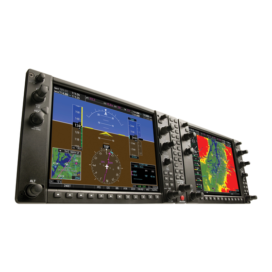
PFD 2; the GDU 1500 unit, a 15 inch LCD display with 1024x768 resolution, is configured as a MFD. All displays provide control and display of nearly all functions of the G1000 integrated cockpit system. The PFD displays are located on either side of the MFD, with the stand-by instruments located between the Pilot’s PFD (PFD 1) and the MFD. -
Page 20: Figure 2-2, Audio Panel
The dedicated AFCS controls on the GMC 710 allow crew control interface with the various GFC 700 autopilot / flight director functions. GMC 710 controls are discussed in detail in the G1000/King Air 300/B300 Series Cockpit Reference Guide. The GMC 710 is powered by No. 1 Triple Fed Bus. -
Page 21: Figure 2-4, Fms Controller
The GCU 477 functions as the primary control interface to the GDU 1500 MFD. The GCU 477 provides alphanumeric, softkey, and flight planning function keys used to interface with the G1000; the MFD does not possess any knobs or controls other than softkeys. The GCU 477 is powered by No. 3 Triple Fed Bus. -
Page 22: Figure 2-6, Gia Unit
GPS receiver, Flight Director, and system integration microprocessors. The GIAs also serve as a communication interface to all other G1000 LRUs in the system. Each GIA 63W communicates directly with the on-side GDU 1040A display using a HSDB Ethernet connection. Both GIAs are located remotely in the nose equipment bay. -
Page 23: Figure 2-7, Gea Unit
2.1.7 GEA 71 Engine/Airframe Unit (2) The Garmin GEA 71 Engine/Airframe Units provide engine/airframe data to the G1000 system. Data received from transducers/sensors is processed and sent to GIA 63Ws (via RS-485 digital interface), and subsequently to the GDU 1500 MFD. Engine parameters are normally displayed on the MFD. In the event of MFD failure, the engine parameters can be displayed on PFD 1 and/or PFD 2 using display reversion. -
Page 24: Figure 2-8, Air Data Computer
Figure 2-8, Air Data Computer 2.1.9 OAT Probe (2) The Garmin GTP 59 OAT Probes provide the GDC 7400 with air temperature data. The OAT probes are mounted to the bottom of the fuselage at F.S. 113.5. Figure 2-9, OAT probe... -
Page 25: Figure 2-10, Ahrs
GRS 77 Attitude & Heading Reference System (2) The Garmin GRS 77 AHRS units provide attitude and heading information to the G1000 system. The units, mounted in the nose equipment bay, contain advanced tilt sensors, accelerometers, and rate sensors. The unit interfaces with the GDC 7400 and GMU44 Magnetometer and utilizes GPS signals from the GIA 63Ws. -
Page 26: Figure 2-12, Gdl 69A Datalink
The GDL 59 unit interfaces to the Garmin Integrated Flight Deck via the GDL69A using HSDB. The GDL 59 is located in the aft cabin floor area, just forward of the cabin door. The GDL 59 is powered from the Right Gen Avionics Bus. -
Page 27: Figure 2-14, Gsr 56 Satellite Receiver
2.1.14 GSR 56 Satellite Receiver (optional) The GSR 56 provides airborne low speed data link and voice communication capability to Garmin Integrated Flight Deck installations. The GSR 56 contains a transceiver that operates on the Iridium Satellite network. The GSR 56 interfaces directly to the GDL 59 via an RS-232 interface. The GSR 56 is located in the aft cabin floor area, just forward of the cabin door. -
Page 28: Figure 2-17, Weather Radar
GSA 80 Servos and GSM 86 Servo Gearboxes (3) The Garmin GFC 700 AFCS uses GSA 80 high torque servos to control aircraft pitch, pitch trim and roll. The pitch trim variant of the GSA 80 is a high speed servo actuator. The GSA 80 contains a motor-control and monitor circuit board, as well as a solenoid and a brushless DC motor. -
Page 29: Figure 2-19, Gsa 9000 / Gsm 9100
GSA 9000 Servo and GSM 9100 Servo Gearbox The Garmin GFC 700 AFCS uses a GSA 9000 servo to control aircraft yaw damper/turn coordination and rudder boost. The GSA 9000 contains a motor-control and monitor circuit board, as well as a solenoid and a brushless DC motor. -
Page 30: G1000 Optional Interfaces
Optional equipment interfaces include lightning detection, traffic, transponder, radio altimeter, ADF and DME systems. The G1000 also provides a general purpose ARINC bus for use with third party entertainment and cabin equipment. Refer to wiring diagram listed in Table 1-2, for specific interface information. -
Page 31: Electrical Power Distribution
Standby Battery. This standby battery power is independent from the normal electrical system and provides redundant power for the standby instruments in the event that all other electrical power is lost. G1000 / GFC 700 System Maintenance Manual - 300/B300 Series King Air Page 2-13... -
Page 32: Figure 2-20, 300/B300 Electrical Distribution (Post G1000 Stc)
Figure 2-20, 300/B300 Electrical Distribution (Post G1000 STC) Page 2-14 G1000 / GFC 700 System Maintenance Manual - 300/B300 Series King Air Revision 1 190-00716-01... -
Page 33: Figure 2-21, G1000 Component Power Sources
Figure 2-21, G1000 Component Power Sources G1000 / GFC 700 System Maintenance Manual - 300/B300 Series King Air Page 2-15 190-00716-01 Revision 1... -
Page 34: Pitot/Static System
Pitot/Static System The following schematic shows the pitot-static system as modified by this installation: Figure 2-22, Pitot/Static System (Post G1000 STC) Page 2-16 G1000 / GFC 700 System Maintenance Manual - 300/B300 Series King Air Revision 1 190-00716-01... -
Page 35: Shield Block Grounds
Shield Block Grounds The connectors on Garmin G1000 LRUs utilize the Shield Block grounding system to provide necessary ground reference to wire shielding and/or transducers. The shield block termination method allows multiple grounds to be terminated directly to a block mounted to the connector backshell assembly. Shielding and grounding requirements for all other LRUs and connectors are shown in the respective install drawings. - Page 36 This page intentionally left blank. Page 2-18 G1000 / GFC 700 System Maintenance Manual - 300/B300 Series King Air Revision 1 190-00716-01...
-
Page 37: G1000 Control & Operation
G1000 Control & Operation All control and operation of G1000 equipment as normally used in flight occurs through the PFDs, MFD, GMC 710, GCU 477 and GMA 1347D audio panel. Figure 3-1 through Figure 3-6 identify various interface buttons for these units. -
Page 38: Figure 3-2, Gdu 1500 Control Interface
Figure 3-3, G1000 Softkeys 3.1.2 FMS Knob The FMS knob is the primary control for the G1000 system. Operation is similar to the Garmin 400/500 Series units. To cycle through different configuration screens: To change page groups: Rotate the large FMS knob. -
Page 39: Gcu 477 - Mfd Controller
Figure 3-4, MFD Controls (GCU 477 shown) GMC 710 - AFCS Controls The dedicated AFCS controls located on the GMC 710 are discussed in detail in the G1000 CRG. The following figure is provided for reference: Figure 3-5, AFCS Controls (GMC 710 shown) -
Page 40: Gma 1347D Audio Panel
Digital Recording Playback Cabin Intercom Intercom System (ICS) ICS VOL SQ (Small Knob) Master VOL (Large Knob) Reversionary Mode Figure 3-6, GMA 1347D Controls Page 3-4 G1000 / GFC 700 System Maintenance Manual - 300/B300 Series King Air Revision 1 190-00716-01... -
Page 41: G1000 Normal Mode
GDL 59 / GSR 56 Wi-Fi/Satellite (Optional) The G1000 system is now powered in the normal mode. In the normal operating mode, data fields that are invalid have large red X’s through them. A valid field does not display a red X. Allow the displays to initialize for approximately one minute. -
Page 42: Reversionary Mode
5-second interval, the timer will repeat the count. Figure 3-8, Automatic Reversion with MFD failure Figure 3-9, Manual Reversion with pilot PFD failure Page 3-6 G1000 / GFC 700 System Maintenance Manual - 300/B300 Series King Air Revision 1 190-00716-01... -
Page 43: Configuration Mode Overview
Configuration Module. Refers to an ‘active’ setting or parameter currently being used by the LRU. LRUs store the ACTIVE: ‘active’ settings within internal memory. G1000 / GFC 700 System Maintenance Manual - 300/B300 Series King Air Page 3-7 190-00716-01 Revision 1... -
Page 44: Figure 3-10, Set>Actv Diagram
Master Configuration Module LRU Memory SET>ACTV Softkey Configuration Correct Master Configuration Module LRU Memory Master Configuration Module LRU Memory Figure 3-10, SET>ACTV Diagram Page 3-8 G1000 / GFC 700 System Maintenance Manual - 300/B300 Series King Air Revision 1 190-00716-01... -
Page 45: Figure 3-11, Loss Of Communication
Red X: Expected data is not received. A red X could also indicate that a parameter/component is invalid. • White N/A: Expected data is OFF, or no data is expected. Figure 3-13, Data Transmission Indicators G1000 / GFC 700 System Maintenance Manual - 300/B300 Series King Air Page 3-9 190-00716-01 Revision 1... - Page 46 OTHER Page * (Stormscope) CAL Page Group 1. Fuel Tank Calibration 2. Flaps & Trim Calibration 3. HSCM Calibration * Appears only if option is installed. Page 3-10 G1000 / GFC 700 System Maintenance Manual - 300/B300 Series King Air Revision 1 190-00716-01...
-
Page 47: G1000 / Gfc 700 Software Information
G1000 software and configuration files are controlled via the approved software image part number listed on the General Arrangement drawing listed in Table 1-2. This software image is loaded into the G1000 using a software loader card. The installer shall create this software loader card by downloading the approved software image in accordance with section 3.8.2. - Page 48 Loader Card Creation The software image is an executable self-extracting file which builds the correct file structure onto an SD card for use loading software to the G1000 and GFC700. To obtain the current file, follow the procedures outlined below.
- Page 49 Ensure files are not necessary or card is empty before proceeding. Version of card being created Enter SD card Click next once card is inserted G1000 / GFC 700 System Maintenance Manual - 300/B300 Series King Air Page 3-13 190-00716-01 Revision 1...
- Page 50 8. Ensure the card and correct drive letter is used, and click next. Select drive 9. A window will pop-up onto the screen to indicate file progress. Copy of files to selected drive Page 3-14 G1000 / GFC 700 System Maintenance Manual - 300/B300 Series King Air Revision 1 190-00716-01...
- Page 51 Software files are defined by part number and version number on the General Arrangement drawing. See Table 1-2 for the correct General Arrangement drawing part numbers. Each G1000 / GFC 700 LRU reports the software version it currently contains to the user in two places.
-
Page 52: Figure 3-14, G1000 Lru Configuration File Storage
3.8.5 Configuration File Storage The G1000 system is designed to store all configuration settings in various places so that the configuration is retained in the aircraft during maintenance of units. During system configuration, each file is sent directly to the applicable LRU where it is stored in local LRU memory (except GRS 77 &... -
Page 53: Figure 3-15, Grs/Gdc Configuration Settings Storage
Data is that is not installation-specific. Data is stored from factory calibrations. stored from factory calibrations. Figure 3-15, GRS/GDC Configuration Settings Storage G1000 / GFC 700 System Maintenance Manual - 300/B300 Series King Air Page 3-17 190-00716-01 Revision 1... -
Page 54: G1000 Software/Configuration Procedure
The following diagram depicts an overview of the software/configuration sequence for the G1000 system. This applies mostly to a new G1000 system which has not previously been powered up and is for informative purposes only. - Page 55 1. Connect a ground power unit to the external power receptacle and turn on the ground power unit. 2. Set the BAT, EXT PWR and AVIONICS MASTER PWR switches to ON. 3. With the G1000 system powered on, pull the MFD, PFD 1 (PRI), PFD 1 (SEC), and PFD 2 circuit breakers.
-
Page 56: Figure 3-17, Airframe Options
4. Once the propeller type is selected the cursor moves to the PRODUCT windo. Select the software and/or configuration which is to be loaded for each G1000 LRU. Page 3-20 G1000 / GFC 700 System Maintenance Manual - 300/B300 Series King Air Revision 1 190-00716-01... -
Page 57: Figure 3-19, Configuration/Software Load Page
CHK ALL softkey is recommended. 5. After verifying that the desired software and configuration files are checked, press the LOAD softkey. The G1000 system automatically begins loading software and default configuration files to the selected LRUs in the proper order. -
Page 58: Figure 3-20, System Status
General Arrangement drawing listed in Table 1-2. Software Configuration is a critical part of the G1000 operation and must be verified before returning an aircraft to service. If any software version and/or part number does not match those specified by the General Arrangement drawing, or if the software is not successfully loaded, DO NOT continue. -
Page 59: Table 3-1, Software Verification
GRS1 FPGA PFD1 GFC CERT RC GRS2 PFD1 FPGA GFC CERT RM GRS2 FPGA PFD2 GFC CERT YC GSA PTCH CTL PFD2 FPGA G1000 / GFC 700 System Maintenance Manual - 300/B300 Series King Air Page 3-23 190-00716-01 Revision 1... -
Page 60: Taws-A Support Configuration
• Green “PASS” in Configuration column for ALERTS. • “Upload Complete………….COMPLETE” in the summary box. 6. Press ENT key on PFD1 to acknowledge upload complete. 7. Deactivate cursor. Page 3-24 G1000 / GFC 700 System Maintenance Manual - 300/B300 Series King Air Revision 1 190-00716-01... -
Page 61: Taws-A Voice No Callout Option Configuration
• Green “PASS” in Configuration column for AIRFRAME. • “Upload Complete………….COMPLETE” in the summary box. 6. Press ENT key on PFD1 to acknowledge upload complete. 7. Deactivate cursor. G1000 / GFC 700 System Maintenance Manual - 300/B300 Series King Air Page 3-25 190-00716-01 Revision 1... -
Page 62: Taws-A Voice Callout Option Configuration
• Green “PASS” in Configuration column for AIRFRAME. • “Upload Complete………….COMPLETE” in the summary box. 6. Press ENT key on PFD1 to acknowledge upload complete. 7. Deactivate cursor. Page 3-26 G1000 / GFC 700 System Maintenance Manual - 300/B300 Series King Air Revision 1 190-00716-01... -
Page 63: Adf Option Configuration
• Green “PASS” in Configuration column for GIA2, GMA PIL, and GMA COPIL. • “Upload Complete………….COMPLETE” in the summary box. 6. Press ENT key on PFD1 to acknowledge upload complete. 7. Deactivate cursor. G1000 / GFC 700 System Maintenance Manual - 300/B300 Series King Air Page 3-27 190-00716-01 Revision 1... -
Page 64: Dme Option Configuration
• Green “PASS” in Configuration column for GIA1, GMA PIL and GMA COPIL. • “Upload Complete………….COMPLETE” in the summary box. 6. Press ENT key on PFD1 to acknowledge upload complete. 7. Deactivate cursor. Page 3-28 G1000 / GFC 700 System Maintenance Manual - 300/B300 Series King Air Revision 1 190-00716-01... -
Page 65: Rad Alt Option Configuration
• Green “PASS” in Configuration column for GIA2. • “Upload Complete………….COMPLETE” in the summary box. 6. Press ENT key on PFD1 to acknowledge upload complete. 7. Deactivate cursor. G1000 / GFC 700 System Maintenance Manual - 300/B300 Series King Air Page 3-29 190-00716-01 Revision 1... -
Page 66: Tcas Ii Traffic System Option Configuration
3.16 TCAS II Traffic System Option Configuration Follow this procedure to enable the Collins TCAS II traffic system function for the G1000 system if required. Do not accomplish the GTX33/33D configuration procedure per Section 3.21. NOTE The G1000 can only be configured for TIS or TCAS II but not both. -
Page 67: Tas/Tcas I Traffic System Option Configuration
3.17 TAS/TCAS I Traffic System Option Configuration Follow this procedure to enable a non-Garmin TAS/TCAS I traffic system function for the G1000 system if required. NOTE The G1000 can only be configured for TIS or TAS/TCAS I, but not both. Performing this procedure will automatically disable the TIS function. -
Page 68: Gts 8Xx Tas/Tcas1 Traffic System Configuration
3.18 GTS 8XX TAS/TCAS1 Traffic System Configuration Follow this procedure to enable the GTS 8XX traffic system function for the G1000 system if required. NOTE The G1000 can only be configured for TIS or TAS/TCAS but not both. Performing this procedure will automatically disable the TIS function. Coordinate this configuration with Section 7.13 “GTS 8XX Traffic System Functional Check”. -
Page 69: Lightning System Option Configuration
Lightning System Option Configuration Follow this procedure to enable the lightning system option (WX-500) for the G1000 system if required. 1. With the loader card in the top slot of PFD1 and PFD1 in configuration mode, select the “System Upload”... -
Page 70: Lightning System Option Configuration Load Confirmation
<aircraft heading> Inhibit Line Antenna Mount Bottom J3-3 Open 4. Deactivate the cursor. NOTE The DATA window is only updated once every five seconds. Page 3-34 G1000 / GFC 700 System Maintenance Manual - 300/B300 Series King Air Revision 1 190-00716-01... -
Page 71: Gtx 33/33D Configuration
6. Press ENT key on PFD1 to acknowledge upload complete. 7. Deactivate cursor. 8. On the MFD, verify that the GTX software part number and version matches the information in G1000/GFC 700 AFCS, King Air 300/B300, 005-00629-02, General Arrangement drawing. -
Page 72: Esp Support Option Configuration
• Green “PASS” in Configuration column for AIRFRAME, ALERTS, GIA1 and GIA2. • “Upload Complete………….COMPLETE” in the summary box. 6. Press ENT key on PFD1 to acknowledge upload complete. 7. Deactivate cursor. Page 3-36 G1000 / GFC 700 System Maintenance Manual - 300/B300 Series King Air Revision 1 190-00716-01... -
Page 73: Gdl 59 Wi-Fi Data Link Option Configuration
8. On the MFD, verify that the GDL59 software part number and version matches the information in G1000/GFC 700 AFCS, King Air 300/B300, 005-00629-02, General Arrangement drawing. G1000 / GFC 700 System Maintenance Manual - 300/B300 Series King Air Page 3-37... -
Page 74: Gsr 56 Satellite Reciever Option Configuration
5. Use the small FMS knob to select YES and press the ENT key. 6. After GDL 59 is configured, press the ENT key. Page 3-38 G1000 / GFC 700 System Maintenance Manual - 300/B300 Series King Air Revision 1 190-00716-01... -
Page 75: Flight Data Recorder Option Configuration
IMPORTANT! A separate approval is required for the installation of a Flight Data Recorder system. This configuration option only allows the G1000 to interface to a Flight Data Recorder system. G1000 / GFC 700 System Maintenance Manual - 300/B300 Series King Air... -
Page 76: Figure 3-37, Fdr Configuration
8. On the MFD, verify that the GSD software part number and version matches the information in G1000/GFC 700 AFCS, King Air 300/B300, 005-00629-02, General Arrangement drawing. Page 3-40 G1000 / GFC 700 System Maintenance Manual - 300/B300 Series King Air Revision 1 190-00716-01... -
Page 77: Flitecharts Configuration
If ChartView has previously been enabled, and is no longer desired, follow the procedures outlined in this section to return the G1000 system to the basic FliteChart functions. If ChartView has not been enabled, the following procedure is not required. -
Page 78: Taws-B Enable
General Arrangement Drawing 005-00629-02, will be required for this procedure. NOTE The G1000 has various features that require the use of unlock/enable cards to activate the feature. Throughout this document these cards are generically referred to as ‘enable cards’. In some cases, the actual label on the physical card may say ‘unlock’. -
Page 79: Taws-A Enable
General Arrangement Drawing 005-00629-02, will be required for this procedure. NOTE The G1000 has various features that require the use of unlock/enable cards to activate the feature. Throughout this document these cards are generically referred to as ‘enable cards’. In some cases, the actual label on the physical card may say ‘unlock’. -
Page 80: Supplemental Database Loading
13. Press the PFD1 DB softkey again to toggle to PFD2 DB. Scroll through all of the databases contained in the PFD2 and confirm that the correct databases are loaded. Page 3-44 G1000 / GFC 700 System Maintenance Manual - 300/B300 Series King Air Revision 1 190-00716-01... -
Page 81: Svs/Pathways Enable
Terrain/Obstacle/SafeTaxi database card installed in the lower slot. NOTE When the SVS/Pathways option is enabled for the first time the G1000 writes its unique system ID to the physical card and locks the files to this unique ID. This prevents the SVS/Pathways unlock card from ever being used to activate the SVS/Pathway feature in other G1000 systems. -
Page 82: Esp Enable
Ensure that the “ESP Support (no AOA)” configuration has been loaded per Section 3.21. NOTE The G1000 has various features that require the use of unlock/enable cards to activate the feature. Throughout this document these cards are generically referred to as ‘enable cards’. -
Page 83: Aircraft Registration Number Entry
5. After each configuration setting change, press the ENT key to configure the transponders. 6. Press the ENT key on PFD1 to acknowledge prompt. 7. After completing transponder configuration, deactivate the cursor. G1000 / GFC 700 System Maintenance Manual - 300/B300 Series King Air Page 3-47 190-00716-01... -
Page 84: Gdl 69 Alternate Antenna Location Configuration
Figure 3-45, GDL 69 Cable Loss 5. Verify GDL 69 is configured, then press the ENT key on PFD1 to acknowledge. Figure 3-46, GDL 69 Cable Loss Configured Page 3-48 G1000 / GFC 700 System Maintenance Manual - 300/B300 Series King Air Revision 1 190-00716-01... -
Page 85: Splash Screen Loading
NOTE Any time software and/or configuration is loaded to the system, the splash screens may need to be reloaded to all three display units. G1000 / GFC 700 System Maintenance Manual - 300/B300 Series King Air Page 3-49 190-00716-01 Revision 1... -
Page 86: Navigation Database Loading
A new navigation database cycle may be loaded before it is effective. The new database will be stored on the G1000 bottom SD card until it becomes effective. The G1000 will automatically update to use the new database at the first on-ground power-on after its effectivity date. -
Page 87: Figure 3-47, Navigation Database Synchronization
14. Press the PFD1 DB softkey again to toggle to PFD2 DB. Scroll through all of the databases contained in the PFD2 and confirm that the correct databases are loaded. G1000 / GFC 700 System Maintenance Manual - 300/B300 Series King Air Page 3-51... -
Page 88: Configuration Of Navigation Map For Traffic System
MFD, count 2 keys to the left), reset the MFD circuit breaker. 5. When prompted to clear user settings, select the YES softkey on each unit. Page 3-52 G1000 / GFC 700 System Maintenance Manual - 300/B300 Series King Air Revision 1 190-00716-01... -
Page 90: Servicing Information
Servicing Information G1000/GFC 700 LRU maintenance is ‘on condition’ only. No component-level overhaul is required for the G1000/GFC 700 installation. 4.2.1 On Condition Servicing ‘On Condition’ replacement and/or servicing should occur when an item exhibits conditions, symptoms, and/or abnormalities defined in Section 5 of this manual. Replacement and/or servicing should be made only after the technician troubleshoots the system to the extent determined necessary by using the guidance in this manual along with common avionics maintenance practices. - Page 91 • Calibrated Flight Control Cable Tension Meter or equivalent • Servo Gearbox Slip Clutch Adjustment Tool – Garmin P/N T10-00110-01 and a 2 Amp, 24 V, DC Power Supply • Calibrated torque wrench capable of measuring 0 – 70 in/lbs •...
-
Page 92: Maintenance Intervals
Special Inspection Items - Calendar limited inspections have a tolerance of ± 12 days per 12 calendar months. The intention of Garmin is to align this maintenance program as best possible with the existing King Air 300/B300 inspection program. For a complete description of the King Air inspection program, refer to the Super King Air 300 or B300 Maintenance Manual listed in Table 1-2. - Page 93 GMC 710 6.14 Removal & Replacement GCU 477 6.13 GTS 8XX Traffic Unit 6.31 GPA 65 PA/LNA Unit 6.32 GDL 59 Wi-Fi 6.34 Datalink G1000 / GFC 700 System Maintenance Manual - 300/B300 Series King Air Page 4-5 190-00716-01 Revision 1...
- Page 94 Refer to Master Drawing List, listed in Table GSA 9000 Servos 1-2, for installation drawings. * Denotes Airworthiness Limitation Maintenance Requirement (See Section 4.1) Page 4-6 G1000 / GFC 700 System Maintenance Manual - 300/B300 Series King Air Revision 1 190-00716-01...
- Page 95 Inspect the antenna/probe and surrounding On Condition or Antenna installation per Table 4-9. Actual or Suspected * Denotes Airworthiness Limitation Maintenance Requirement (See Section 4.1) G1000 / GFC 700 System Maintenance Manual - 300/B300 Series King Air Page 4-7 190-00716-01 Revision 1...
- Page 96 (standby compass checked during existing maintenance) Annunciator/Switch – Removal & Replacement 6.23 On Condition Standby Battery * Denotes Airworthiness Limitation Maintenance Requirement (See Section 4.1) Page 4-8 G1000 / GFC 700 System Maintenance Manual - 300/B300 Series King Air Revision 1 190-00716-01...
-
Page 97: Table 4-2, Discontinued Maintenance Intervals
Super King Air 300 or B300 Maintenance Manual, or other appropriate maintenance manual, in cases where the requirements conflict. G1000 / GFC 700 System Maintenance Manual - 300/B300 Series King Air Page 4-9 190-00716-01... -
Page 98: Visual Inspection
Inspect Ground blocks for security of attachment, corrosion or other defects. Ensure all connectors are securely fastened. Page 4-10 G1000 / GFC 700 System Maintenance Manual - 300/B300 Series King Air Revision 1 190-00716-01... -
Page 99: Table 4-5, Pilot's Compartment Visual Inspection Procedure
Table 1-2. Pay particular attention to possible areas of chaffing. harness Inspect all other exposed G1000 / GFC wiring and coax for chafing, damage, proper routing of wire bundles and security of attachment in accordance with AC 43.13-1B, Chapter 11, Section 8, Paragraph 11-96 and the Cabin Wire Harness Routing drawing, listed in Table 1-2. - Page 100 Inspect that all required placards are installed. Placards must be legible, secure and in Placards good condition. Refer to the Main Instrument Panel Installation drawing listed in Table 1-2. Page 4-12 G1000 / GFC 700 System Maintenance Manual - 300/B300 Series King Air Revision 1 190-00716-01...
-
Page 101: Table 4-7, Cabin Area Visual Inspection Procedure
(GTS 8XX traffic attachments to the harness connector assembly as well as the integrity of the option only) individual shields and their attachment. G1000 / GFC 700 System Maintenance Manual - 300/B300 Series King Air Page 4-13 190-00716-01 Revision 1... -
Page 102: Table 4-8, Rear Fuselage And Empennage Visual Inspection Procedure
AC 43.13-1B, Chapter 11, Section 8, Paragraph 11-96 and the Tail Wire Harness Routing drawing, listed in Table 1-2. Pay particular attention to possible areas of chaffing. Reinstall the GMU 44. Page 4-14 G1000 / GFC 700 System Maintenance Manual - 300/B300 Series King Air Revision 1 190-00716-01... -
Page 103: Electrical Bonding Test
Phase 3 Electrical Bonding Test and Phase 4 Electrical bonding test. This places the bonding test requirement for each G1000 LRU in the same phase as the visual inspection of that zone to minimize access requirements. - Page 104 Example: If the measured current is 1.2 amps, (20% high from the target 1 amp current), then the allowable voltage measurement would be 20% high, 2.5 milli-volts would now be 3.0 milli-volts. Page 4-16 G1000 / GFC 700 System Maintenance Manual - 300/B300 Series King Air Revision 1 190-00716-01...
- Page 105 GSR 56 top: __________ milli-volts (if installed) • GDL 59 top: __________ milli-volts (if installed) • GSD 41 top: __________ milli-volts (if installed) G1000 / GFC 700 System Maintenance Manual - 300/B300 Series King Air Page 4-17 190-00716-01 Revision 1...
-
Page 106: Grs 77 Earth Magnetic Field Updates
GRS 77 remains a Garmin-supported product. The G1000 system alerts the operator that the magnetic field database is out of date by issuing the message “AHRS SERVICE – AHRS Magnetic-field model needs update”. Garmin will distribute update instructions when updates are available. -
Page 107: Flaps-In-Motion Discrete Input Check
Flaps-in-motion Discrete Input Check To perform this check, all G1000 and GFC 700 equipment must be installed and operational. Start PFD1 in Configuration Mode and go to the GIA Page Group and select the GIA I/O Configuration Page using the FMS knob. Perform the following checks:... -
Page 108: Gsm 86 Slip Clutch Torque Check Procedure
GSM 86 Slip Clutch Torque Check Procedure Perform either the Automated Slip Clutch Test Procedure per Section 4.9.1 or the Manual Slip Clutch Test Procedure per Section 4.9.2. To perform the procedure, all G1000 and GFC 700 equipment must be installed and operational. -
Page 109: Table 4-10, Measured Torque
Torque (in-lbs) Pitch Roll Pitch Trim Table 4-10, Measured Torque * This value valid only with the GSM86 continuous travel servo gearbox (p/n 011-01904-01) G1000 / GFC 700 System Maintenance Manual - 300/B300 Series King Air Page 4-21 190-00716-01 Revision 1... -
Page 110: G1000 Redundant Connection Check
1. Connect a ground power unit to the external power receptacle and turn on the ground power unit. 2. Set the BAT, EXT PWR and AVIONICS MASTER PWR switches to ON. 3. With the G1000 system in normal mode, pull the following circuit breakers on the right hand circuit breaker panel: •... - Page 111 13. Press the DISPLAY BACK UP button on the Co-pilot’s GMA 1347D audio panel to return to normal mode. 14. Close the PFD 1 (PRI) and PFD 1 (SEC) circuit breakers and wait for PFD 1 to initialize: G1000 / GFC 700 System Maintenance Manual - 300/B300 Series King Air Page 4-23 190-00716-01...
- Page 112 If equipped with ADF and/or DME, ADF/DME windows flag invalid. 9. Restore power to both GIA units. The G1000 Redundant Connections Check is complete. Page 4-24 G1000 / GFC 700 System Maintenance Manual - 300/B300 Series King Air Revision 1 190-00716-01...
-
Page 113: Engine Data Check (Gia 1 Or Gia 2 Inoperative)
This procedure checks the pitch trim (PTRM) annunciation from both GIA 1 and GIA 2 and the mis-trim AFCS status alerts. 1. Ensure the G1000 is in normal mode, autopilot is not engaged, and the mode controller XFR key is selected to the pilot side. - Page 114 33. Verify that the amber RUD→ annunciator is displayed on both PFD 1 and PFD 2. 34. Disengage autopilot. 35. The Trim Annunciator Check is complete. Page 4-26 G1000 / GFC 700 System Maintenance Manual - 300/B300 Series King Air Revision 1 190-00716-01...
-
Page 115: G1000 Miscompare Checks
14. Replace AHRS1 to normal attitude and verify that attitude display on PFD1 displays current aircraft attitude. 15. Use the AFCS mode controller to re-engage autopilot. G1000 / GFC 700 System Maintenance Manual - 300/B300 Series King Air Page 4-27 190-00716-01... -
Page 116: Gia Cooling Fans Operational Check
This procedure will verify that airflow is present from the ported avionics cooling fans to the #1 and #2 GIA units. The fan speed monitoring circuits and annunciations are checked by the G1000 Cooling Fan Fail Annunciation Check in Section 8.1.4 and a Visual Inspection of the fans and hoses is accomplished in Section 4.4. -
Page 117: Standby Battery Periodic Checks
0-30 VDC, 20A capacity Fluke Model 8050A Load Resistor 7Ω +/- 1% 250 watt Stopwatch Capable of measuring to the minute Figure 4-4, Standby Battery G1000 / GFC 700 System Maintenance Manual - 300/B300 Series King Air Page 4-29 190-00716-01 Revision 1... - Page 118 If the INDIVIDUAL CELL MONITOR LED DS12 is the only LED not illuminated, proceed to the Cell Isolation Test. 3) Connect Digital Voltmeter leads to J1 connector pins 11 (+) and 7 (-). Page 4-30 G1000 / GFC 700 System Maintenance Manual - 300/B300 Series King Air Revision 1 190-00716-01...
-
Page 119: Figure 4-5, Power Supply Connection
11 (+) and 7 (-) and charge the unit for 16 hours. The batteries should reach 80% capacity within 1 hour and full charge at 16 hours. Figure 4-5, Power Supply Connection G1000 / GFC 700 System Maintenance Manual - 300/B300 Series King Air Page 4-31 190-00716-01... -
Page 120: Rudder Boost Operational Check
RUD BOOST OFF annunciator illuminates. 15. Place the R BLEED AIR CONTROL SWITCH in the OPEN position. Verify RUD BOOST OFF annunciator extinguishes. Page 4-32 G1000 / GFC 700 System Maintenance Manual - 300/B300 Series King Air Revision 1 190-00716-01... -
Page 121: Troubleshooting
Troubleshoot the G1000 system by first identifying, then isolating the specific failure to the responsible LRU. There are several indications that the G1000 presents to the pilot or technician, showing overall system condition. A course of action should be determined based on the information presented on the display. -
Page 122: G1000 Alerting System
Pressing the ALERTS softkey again removes the Alerts window from the display. Softkey Annunciation: When the G1000 Alerting System issues an alert, the ALERTS softkey is used as a flashing annunciation to accompany the alert. During the alert, the ALERTS softkey label changes to ADVISORY as shown in Figure 5-3. - Page 123 Aural & Audio Alerts The G1000 system is capable of issuing audio and aural (voice) alerts for various situations. The following alerts are utilized by the G1000: Alert Name Purpose Traffic (voice) Traffic Advisory No Traffic (voice) Traffic Unavailable “Minimums, Minimums” (voice)
-
Page 124: System Annunciations
• Amber question mark (?) = data path status is unknown • Green checkmark ( )= data path is known to be good Page 5-4 G1000 / GFC 700 System Maintenance Manual - 300/B300 Series King Air Revision 1 190-00716-01... - Page 125 Check the PFD1/GMC 710 interconnect wiring for faults. Replace GMC 710 if problem remains. PFD1/GMC 710 data path functionality is unknown. Reload Amber PFD1 configuration file. G1000 / GFC 700 System Maintenance Manual - 300/B300 Series King Air Page 5-5 190-00716-01 Revision 1...
- Page 126 Check the PFD1/GDC 7400 #1 interconnect wiring for faults. Replace GDC 7400 #1 if problem remains. PFD1/GDC 7400 #1 data path functionality is unknown. Reload Amber PFD1 configuration file. Page 5-6 G1000 / GFC 700 System Maintenance Manual - 300/B300 Series King Air Revision 1 190-00716-01...
- Page 127 Check the PFD2/GMC 710 interconnect wiring for faults. Replace GMC 710 if problem remains. PFD2/GMC 710 data path functionality is unknown. Reload Amber PFD2 configuration file. G1000 / GFC 700 System Maintenance Manual - 300/B300 Series King Air Page 5-7 190-00716-01 Revision 1...
- Page 128 Check the PFD2/GDC 7400 #2 interconnect wiring for faults. Replace GDC 7400 #2 if problem remains. PFD2/GDC 7400 #2 data path functionality is unknown. Reload Amber PFD2 configuration file. Page 5-8 G1000 / GFC 700 System Maintenance Manual - 300/B300 Series King Air Revision 1 190-00716-01...
- Page 129 Check the MFD1/GCU 477 interconnect wiring for faults. • Replace GCU 477. Replace MFD if problem remains. MFD1/GCU data path functionality is unknown. Reload MFD1 Amber configuration file. G1000 / GFC 700 System Maintenance Manual - 300/B300 Series King Air Page 5-9 190-00716-01 Revision 1...
- Page 130 Check the GIA1/GTX 33 #1 interconnect wiring for faults. Replace GTX 33 #1 if problem remains. GIA1/GTX 33 #1 data path functionality is unknown. Reload Amber GIA1 configuration files. Page 5-10 G1000 / GFC 700 System Maintenance Manual - 300/B300 Series King Air Revision 1 190-00716-01...
- Page 131 Check the GIA1/GMA 1347D #1 interconnect wiring for faults. GIA1/GMA 1347D #1 data path functionality is unknown. Amber Reload GIA1 configuration files. G1000 / GFC 700 System Maintenance Manual - 300/B300 Series King Air Page 5-11 190-00716-01 Revision 1...
- Page 132 Check the GIA1/GRS 77 #1 interconnect wiring for faults. GIA1/GRS 77 #1 data path functionality is unknown. Reload Amber GIA1 configuration files. Page 5-12 G1000 / GFC 700 System Maintenance Manual - 300/B300 Series King Air Revision 1 190-00716-01...
- Page 133 Check the GIA2/GTX 33 #2 interconnect wiring for faults. Replace GTX 33 #2 if problem remains. GIA2/GTX 33 #2 data path functionality is unknown. Amber Reload GIA2 configuration files. G1000 / GFC 700 System Maintenance Manual - 300/B300 Series King Air Page 5-13 190-00716-01 Revision 1...
- Page 134 Check the GIA1/GMA 1347D #2 interconnect wiring for faults. GIA1/GMA 1347D #2 data path functionality is unknown. Amber Reload GIA2 configuration files. Page 5-14 G1000 / GFC 700 System Maintenance Manual - 300/B300 Series King Air Revision 1 190-00716-01...
- Page 135 Check the GIA2/GRS 77 #2 interconnect wiring for faults. GIA2/GRS 77 #2 data path functionality is unknown. Reload Amber GIA2 configuration files. G1000 / GFC 700 System Maintenance Manual - 300/B300 Series King Air Page 5-15 190-00716-01 Revision 1...
- Page 136 (if LRU and Card versions are different). CHNL 4 GFC 700 Reference GFC section for further troubleshooting. GIA1/GFC 700 data path functionality is unknown. Reload GIA1 Amber configuration files. Page 5-16 G1000 / GFC 700 System Maintenance Manual - 300/B300 Series King Air Revision 1 190-00716-01...
- Page 137 CHNL 4 GFC 700 different). Reference GFC section for further troubleshooting. GIA2/GFC 700 data path functionality is unknown. Reload Amber GIA2 configuration files. G1000 / GFC 700 System Maintenance Manual - 300/B300 Series King Air Page 5-17 190-00716-01 Revision 1...
- Page 138 5.2.2 System Failure Troubleshooting The following table provides basic troubleshooting guidance for LRU failures. Refer to G1000/GFC 700 Wiring Diagram, listed in Table 1-2, as needed to verify interconnects. Associated Invalid Data Field Solution LRU(s) Low Speed Awareness Band •...
- Page 139 GTP 59 • Replace GDC config module • Replace GDC 7400 with a known good unit: If problem persists, replace the GTP 59. G1000 / GFC 700 System Maintenance Manual - 300/B300 Series King Air Page 5-19 190-00716-01 Revision 1...
- Page 140 If problem persists replace GRS 77 configuration module. Contact Garmin Aviation Product Support if condition continues after replacing the GRS 77 and config module for additional assistance. Page 5-20 G1000 / GFC 700 System Maintenance Manual - 300/B300 Series King Air Revision 1 190-00716-01...
- Page 141 GRS 77 • If this message persists longer than five minutes, & perform AHRS calibration procedures as described in GMU 44 Section 7.7.3. G1000 / GFC 700 System Maintenance Manual - 300/B300 Series King Air Page 5-21 190-00716-01 Revision 1...
- Page 142 Check the GIA/GEA interconnects for faults. Reload configuration files to both GIA’s and the GEA. • If problem persists, replace the GEA 71. Page 5-22 G1000 / GFC 700 System Maintenance Manual - 300/B300 Series King Air Revision 1 190-00716-01...
- Page 143 GEA 71. Replace one part at a time. Refer to Section 7.4.1 to check for correct operation of the sensors and GEA 71 after any part has been replaced. Refer to G1000/GFC 700 Wiring Diagram and Super King Air 300 or B300 Maintenance Manual (listed in Table 1-2) as needed.
- Page 144 5.2.4 ADF/DME Failure A DME or ADF failure is represented by the following red X’s. Refer to G1000/GFC 700 Wiring Diagram and Super King Air 300 or B300 Maintenance Manual (listed in Table 1-2,) as needed. Invalid Field Sensor Solutions •...
-
Page 145: 300/B300 Specific Alerts
Reloading the baseline configuration disables all previously enabled options. NOTE From this point forward, all message advisory alerts presented are common to all G1000 systems and are not specific to the King Air 300/B300. Messages are grouped according to LRU. -
Page 146: Taws Troubleshooting
• A GPWS system failure has Verify radio altimeter input is valid. occurred. • Verify baro altitude and vertical speed input are valid. Page 5-26 G1000 / GFC 700 System Maintenance Manual - 300/B300 Series King Air Revision 1 190-00716-01... -
Page 147: Synthetic Vision And Pathways Troubleshooting
Verify that the alert messages shown in Table 5-2 are not displayed on the PFD Alerts Window. If so, follow the solutions described in Table 5-2. Verify that the G1000 AHRS and heading data are valid on the PFD. Verify 3D terrain presentation does not that a valid GPS 3D position solution is being received. -
Page 148: Figure 5-5, Afcs Annunciation Field
Should a problem be encountered during the operation of the GFC 700, the pilot and technician should first evaluate the overall status and condition of the G1000 system at the AUX – System Status page (on MFD). Any alert messages, annunciations, or other abnormal behaviors should be noted in an effort to pinpoint the fault. -
Page 149: Table 5-3, Afcs Annunciation Troubleshooting
Check the servo wiring and connectors. Ensure the servo is receiving power. • Check the aircraft control adjustments. Elevator Mis-Trim • If mistrim condition still exists, remove and replace the affected servo. G1000 / GFC 700 System Maintenance Manual - 300/B300 Series King Air Page 5-29 190-00716-01 Revision 1... -
Page 150: Table 5-4, Afcs General Troubleshooting
If DATA indicator fails to illuminate or illuminates incorrectly, troubleshoot flap motor & discrete input wiring (refer to G1000/GFC 700 Wiring Diagram, listed in Table 1-2, Page 5-30 G1000 / GFC 700 System Maintenance Manual - 300/B300 Series King Air Revision 1 190-00716-01... -
Page 151: Figure 5-6, Gfc Status Page
ENG CLCH and DRV SRVO softkeys to drive the servo. NOTE Be especially certain that the flight controls are clear and safe to operate before manually driving the servo. G1000 / GFC 700 System Maintenance Manual - 300/B300 Series King Air Page 5-31 190-00716-01 Revision 1... - Page 152 Logs unless the GIA log fault identifies a servo problem. NOTE Thoroughly understanding the operation of the G1000 system in Configuration mode is recommended before starting this procedure. The GFC Status page may be used to check the status of the servos and engage them to aid in troubleshooting To access the GIA and GSA Maintenance Logs, perform the following steps –...
- Page 153 • Stuck switch invalidated parameter: <AXIS> A MET switch in the specified axis is stuck. Check the MET (trim) switches for proper operation. G1000 / GFC 700 System Maintenance Manual - 300/B300 Series King Air Page 5-33 190-00716-01 Revision 1...
- Page 154 AHRS monitor will be assumed valid if on the ground. If this step fails, then make sure the AHRS and ADC is powered up and sending valid attitude data to the G1000. Page 5-34 G1000 / GFC 700 System Maintenance Manual - 300/B300 Series King Air Revision 1 190-00716-01...
- Page 155 This step is checking to make sure the servos have all passed their own PFT. If this step fails, please proceed to servo PFT explanation below. G1000 / GFC 700 System Maintenance Manual - 300/B300 Series King Air Page 5-35...
- Page 156 PFT step 15: PFT completed The PFT has successfully completed. PFT step 16: PFT failed The PFT has failed. Page 5-36 G1000 / GFC 700 System Maintenance Manual - 300/B300 Series King Air Revision 1 190-00716-01...
- Page 157 Any faults that are not listed here indicate an internal problem requiring replacement of the servo. If the items in the Notes column check out ok, replace the servo. G1000 / GFC 700 System Maintenance Manual - 300/B300 Series King Air Page 5-37...
- Page 158 Check the connector strap inputs to the unit “MET STUCK SWTCH” Check the MET switch inputs into the system “MET STATUS DIF” Check the MET switch inputs into the system Page 5-38 G1000 / GFC 700 System Maintenance Manual - 300/B300 Series King Air Revision 1 190-00716-01...
- Page 159 "CERT DATA UNINSTALLED" Upload the certification gain file to the Control board "STRAP CODE MISMATCH" Check the connector strap inputs to the unit G1000 / GFC 700 System Maintenance Manual - 300/B300 Series King Air Page 5-39 190-00716-01 Revision 1...
- Page 160 Check the connector strap inputs to the unit “MET STUCK SWTCH” Check the MET switch inputs into the system “MET STATUS DIF” Check the MET switch inputs into the system Page 5-40 G1000 / GFC 700 System Maintenance Manual - 300/B300 Series King Air Revision 1 190-00716-01...
- Page 161 Maintenance logs can be downloaded to an SD card as a text file (.txt) and emailed to Garmin Aviation Product Support. Please call Garmin Aviation Product Support before you send a Maintenance Log to notify them you are sending it to prevent a delay in response.
- Page 162 12. While you are waiting for the data to be saved to the SD card, record the order of the LRU’s and/or Servos were downloaded so that you can provide that information to Garmin to help decipher the order of the error data.
-
Page 163: Backup Communications Path Checks
5.7.1 Overview The G1000 system architecture is designed with redundant communication ports for several LRUs so that critical information can continue to be displayed in the event of an equipment or wiring failure. Of most importance is flight attitude, heading, and air data information. The GRS 77 and GDC 7400 each have four separate ARINC 429 data lines which are all capable of sending data to the displays. -
Page 164: Gdu 104X Troubleshooting
If card was inserted with the label facing to the right, do not attempt to remove. Return the unit to Garmin for repair. Page 5-44 G1000 / GFC 700 System Maintenance Manual - 300/B300 Series King Air Revision 1 190-00716-01... - Page 165 GDU dimmer input to verify voltage is present. • If display is the MFD, check dimmer input to verify voltage is present. Replace MFD if dimmer voltage is present. G1000 / GFC 700 System Maintenance Manual - 300/B300 Series King Air Page 5-45 190-00716-01 Revision 1...
-
Page 166: Gdu 104X Alerts
The old Terrain and other cards will no longer work as they will remain locked to the old System ID number. Page 5-46 G1000 / GFC 700 System Maintenance Manual - 300/B300 Series King Air Revision 1 190-00716-01... - Page 167 The old Terrain and other cards will no longer work as they will remain locked to the old System ID number. G1000 / GFC 700 System Maintenance Manual - 300/B300 Series King Air Page 5-47 190-00716-01 Revision 1...
- Page 168 PFDs and/or MFD do not Load same type aviation database database type mismatch. Xtalk is match (i.e., different regions: to all displays. off. Americas, International, Atlantic, etc) Page 5-48 G1000 / GFC 700 System Maintenance Manual - 300/B300 Series King Air Revision 1 190-00716-01...
- Page 169 Reducing power usage. temperature range. If problem persists, replace the PFD2. • If problem continues contact Garmin Aviation Product Support for assistance. G1000 / GFC 700 System Maintenance Manual - 300/B300 Series King Air Page 5-49 190-00716-01 Revision 1...
- Page 170 Pilot stored data has been lost. Ensure CLR key is not lost. Recheck settings. stuck on the GDU TEST page. If problem persists, replace PFD1. Page 5-50 G1000 / GFC 700 System Maintenance Manual - 300/B300 Series King Air Revision 1 190-00716-01...
- Page 171 MFD1 VOLTAGE – MFD1 has The MFD supply voltage is low voltage. Reducing power • If input voltage is ok, replace low. usage. MFD. G1000 / GFC 700 System Maintenance Manual - 300/B300 Series King Air Page 5-51 190-00716-01 Revision 1...
- Page 172 • Check interconnect wiring between the GMA’s for faults. occurred. • Replace GMA1. • If problem persists, reinstall GMA1 and replace GMA2. Page 5-52 G1000 / GFC 700 System Maintenance Manual - 300/B300 Series King Air Revision 1 190-00716-01...
- Page 173 The old Terrain and other cards will no longer work as they will remain locked to the old System ID number. G1000 / GFC 700 System Maintenance Manual - 300/B300 Series King Air Page 5-53 190-00716-01 Revision 1...
-
Page 174: Gia 63 Troubleshooting
Weak G/S receiver If problem follows unit, replace GIA. If problem does not follow unit, check NAV antenna, coupler, and cabling for faults. Page 5-54 G1000 / GFC 700 System Maintenance Manual - 300/B300 Series King Air Revision 1 190-00716-01... - Page 175 If clearing nonvolatile memory is unsuccessful and the GPS still can not acquire a position, replace the GIA. If problem does not follow unit, check GPS antenna and cabling. G1000 / GFC 700 System Maintenance Manual - 300/B300 Series King Air Page 5-55 190-00716-01...
-
Page 176: Gia Alert Messages
(Both GIAs must be configured when swapped, see Section 3.9): If problem follows the unit, replace GIA2. If problem persists replace defective GMA 1347D #2. Page 5-56 G1000 / GFC 700 System Maintenance Manual - 300/B300 Series King Air Revision 1 190-00716-01... - Page 177 COM2 TEMP – COM2 over temp. • damage. Reducing transmitter power. If problem persists contact Garmin Aviation Product Support for assistance. G1000 / GFC 700 System Maintenance Manual - 300/B300 Series King Air Page 5-57 190-00716-01 Revision 1...
- Page 178 (or “pressed”) state. when swapped, see Section 3.9): If problem follows unit, replace GIA1. If problem persists, continue to troubleshoot remote transfer switch & wiring. Page 5-58 G1000 / GFC 700 System Maintenance Manual - 300/B300 Series King Air Revision 1 190-00716-01...
- Page 179 The system has detected a failure GPS2 FAIL – GPS2 is inoperative. If problem does not follow the in GPS2 receiver. unit, check GPS antenna and cabling. G1000 / GFC 700 System Maintenance Manual - 300/B300 Series King Air Page 5-59 190-00716-01 Revision 1...
- Page 180 GPS fail. engine failure. etc.). • If GPS receivers can not aquire a position lock, troubleshoot per the “Will not acquire satellites” section. Page 5-60 G1000 / GFC 700 System Maintenance Manual - 300/B300 Series King Air Revision 1 190-00716-01...
- Page 181 GIA2 COOLING – GIA2 over GIA2 has exceeded its operating temperature. temperature range. • Replace GIA2. • If problem persists contact Garmin Aviation Product Support for assistance. G1000 / GFC 700 System Maintenance Manual - 300/B300 Series King Air Page 5-61 190-00716-01 Revision 1...
- Page 182 The G1000 has detected a failure • Replace suspect GIA. in the specified GIA. GIA2 SERVICE – GIA2 needs service. Return unit for repair. Page 5-62 G1000 / GFC 700 System Maintenance Manual - 300/B300 Series King Air Revision 1 190-00716-01...
-
Page 183: Gea Troubleshooting
The old Terrain and other cards will no longer work as they will remain locked to the old System ID number. G1000 / GFC 700 System Maintenance Manual - 300/B300 Series King Air Page 5-63 190-00716-01 Revision 1... -
Page 184: Gtx Troubleshooting
Check wiring between GIA’s and inoperative. The specified GTX 33 is not GTX. responding. XPDR2 FAIL – XPDR 2 is • Replace GTX 33. inoperative. Page 5-64 G1000 / GFC 700 System Maintenance Manual - 300/B300 Series King Air Revision 1 190-00716-01... -
Page 185: Gdl 69A Troubleshooting
MFD and the GDL69/69A unit. Reference the Aircraft Maintenance Manual for instructions on how to check bonding and ground points. If problem persists, replace the GDL 69/69A. G1000 / GFC 700 System Maintenance Manual - 300/B300 Series King Air Page 5-65 190-00716-01 Revision 1... - Page 186 The system has detected an mismatch. Communication incorrect software version loaded See Section 3.9 for the halted. in the GDL 69A. Software Load Procedure. Page 5-66 G1000 / GFC 700 System Maintenance Manual - 300/B300 Series King Air Revision 1 190-00716-01...
-
Page 187: Grs 77/Gmu 44 Troubleshooting
Remove GRS 77 connector and verify there are no bent pins. • Replace the GRS 77. • Contact Garmin for further troubleshooting if required. G1000 / GFC 700 System Maintenance Manual - 300/B300 Series King Air Page 5-67 190-00716-01 Revision 1... - Page 188 The G1000 has detected a • Load AHRS magnetic model field in model database version magnetic model database version both GRS units. mismatch. mismatch. Page 5-68 G1000 / GFC 700 System Maintenance Manual - 300/B300 Series King Air Revision 1 190-00716-01...
- Page 189 Replace GMU 44. HDG FAULT – AHRS2 will be flagged invalid. If problem persists, replace magnetometer fault has occurred. GRS 77. G1000 / GFC 700 System Maintenance Manual - 300/B300 Series King Air Page 5-69 190-00716-01 Revision 1...
-
Page 190: Figure 5-7, Magnetometer Interference Test
1. Initiate the AHRS magnetometer interference test procedure by performing the following steps: 2. On PFD1, enter Configuration Mode and go to GRS/GMU Calibration page as shown in Figure 5-7. Page 5-70 G1000 / GFC 700 System Maintenance Manual - 300/B300 Series King Air Revision 1 190-00716-01... - Page 191 Beacon off 2:40 Rudder full left 2:50 Rudder full right 3:00 Elevator full nose UP 3:10 Elevator full nose DN 3:15 End of test G1000 / GFC 700 System Maintenance Manual - 300/B300 Series King Air Page 5-71 190-00716-01 Revision 1...
-
Page 192: Table 5-5, Magnetometer Interference Test Sequence
6. When the CALIBRATE field is blinking, press the ENT key to begin the procedure, and have a stopwatch ready to begin recording the elapsed time. Page 5-72 G1000 / GFC 700 System Maintenance Manual - 300/B300 Series King Air Revision 1 190-00716-01... - Page 193 Any maximum deviation value greater than 2.5 milliGauss indicates a problem that must be resolved. Compare the corresponding timestamps with the prepared test sequence to identify which action produced the problem. Contact Garmin for assistance in resolving the problem.
-
Page 194: Gdc 7400 Troubleshooting
GDC may be field adjusted per Garmin Service Advisory 0720. Note: Both units may individually be in spec but show a difference Altitude is different than standby in altitude. Do not return the GDC to Garmin for service if not altimeter outside limits. -
Page 195: Gwx 68 Troubleshooting
Load correct software version. See MANIFEST – GWX software incorrect software version Section 3.9 for the Software Load mismatch. Communication halted. loaded in the GWX 68. Procedure. G1000 / GFC 700 System Maintenance Manual - 300/B300 Series King Air Page 5-75 190-00716-01 Revision 1... -
Page 196: Gmc 710 Troubleshooting
MANIFEST – GMC software incorrect software version See Section 3.9 for the Software mismatch. Communication halted. loaded in the GMC 710. Load Procedure. Page 5-76 G1000 / GFC 700 System Maintenance Manual - 300/B300 Series King Air Revision 1 190-00716-01... -
Page 197: Gcu 477 Troubleshooting
Load the correct software version. MANIFEST – GCU software incorrect software version See Section 3.9 for the Software mismatch. Communication halted. loaded in GCU 477. Load Procedure. G1000 / GFC 700 System Maintenance Manual - 300/B300 Series King Air Page 5-77 190-00716-01 Revision 1... -
Page 198: Software/Configuration Troubleshooting
Check and ensure that correct Card Loader was used during load process. Refer to the General Arrangement Drawing. • Reload software to LRU. Page 5-78 G1000 / GFC 700 System Maintenance Manual - 300/B300 Series King Air Revision 1 190-00716-01... - Page 199 GIA1 and GIA2 configuration files. - GMU 44 (software only) • Data path from GIA1 to each LRU must be - GTX 33 operational. G1000 / GFC 700 System Maintenance Manual - 300/B300 Series King Air Page 5-79 190-00716-01 Revision 1...
-
Page 200: Mating/Backplate Connectors
60 61 62 63 64 65 66 67 68 69 70 71 72 73 74 75 76 77 78 G/S ANTENNA CONNECTOR VOR/ILS CONNECTOR (P602) NAV ANTENNA CONNECTOR Figure 5-8, GIA 63W Backplate Connectors Page 5-80 G1000 / GFC 700 System Maintenance Manual - 300/B300 Series King Air Revision 1 190-00716-01... -
Page 201: Figure 5-9, Gea 71 Backplate Connectors
43 44 45 46 47 48 49 50 51 52 53 54 55 5657 58 59 60 61 62 TOP ANTENNA CONNECTOR BOTTOM ANTENNA CONNECTOR Figure 5-11, GTX 33/33D Backplate Connectors Figure 5-12, GDU 1040A/1500 Mating Connector (P10401 or P15001) G1000 / GFC 700 System Maintenance Manual - 300/B300 Series King Air Page 5-81 190-00716-01 Revision 1... -
Page 202: Figure 5-13, Grs 77 Mating Connector (P771)
Figure 5-14, GDC 7400 Mating Connector (P74001) Figure 5-15, GDL 69A Mating Connector (P69A1) Figure 5-16, GCU 477 Mating Connector (P4751) Figure 5-17, GMC 710 Mating Connector (P7101) Page 5-82 G1000 / GFC 700 System Maintenance Manual - 300/B300 Series King Air Revision 1 190-00716-01... -
Page 203: Figure 5-18, Gwx 68 Mating Connector (P681)
Figure 5-19, GTS 820/850 Mating Connectors (Rear View) Figure 5-20, GPA 65 Mating Connector (P651) (Rear View) Figure 5-21, Signal Conditioner Mating Connector (PVIB1) G1000 / GFC 700 System Maintenance Manual - 300/B300 Series King Air Page 5-83 190-00716-01 Revision 1... -
Page 204: Figure 5-22, Gdl 59 Backplate Connector (P591)
51 52 41 42 21 22 Figure 5-24, GSD 41 Backplate Connector (P411) (Rear View) Figure 5-25, GSA 9000 Mating Connector (P90001) (Rear View) Page 5-84 G1000 / GFC 700 System Maintenance Manual - 300/B300 Series King Air Revision 1 190-00716-01... -
Page 205: Standby Attitude Indicator Troubleshooting
• If the airspeeds are different, replace the standby altimeter or contact the manufacturer for further troubleshooting. See Section 6.26 for removal instructions. G1000 / GFC 700 System Maintenance Manual - 300/B300 Series King Air Page 5-85 190-00716-01 Revision 1... -
Page 206: Standby Altimeter Troubleshooting
Connects to wi-fi but cannot send replacement GDL 59 unit must be registered again, even if the MFD report data already shows REGISTERED. Page 5-86 G1000 / GFC 700 System Maintenance Manual - 300/B300 Series King Air Revision 1 190-00716-01... -
Page 207: Gsr 56 Troubleshooting
65 to verify that they are not connected to ground or each other. Ensure that power and ground connections to the GPA 65 are connected in their proper place. G1000 / GFC 700 System Maintenance Manual - 300/B300 Series King Air Page 5-87 190-00716-01 Revision 1... - Page 208 Ensure the port is properly wired to configuration page selected the GTS 8XX and the correct settings are selected on the configuration page. Page 5-88 G1000 / GFC 700 System Maintenance Manual - 300/B300 Series King Air Revision 1 190-00716-01...
-
Page 209: Equipment Removal & Installation
General Arrangement drawing. The Software Manifest page may also be used to check part numbers and versions. G1000 / GFC 700 System Maintenance Manual - 300/B300 Series King Air Page 6-1 190-00716-01... -
Page 210: Gdu 1040A And Gdu 1500
3. Begin to turn the hex nut clockwise. This draws the unit into the rack until seated. Do not over- tighten the nut. 4. Configure and test the GMA 1347D according to Section 7.2. Page 6-2 G1000 / GFC 700 System Maintenance Manual - 300/B300 Series King Air Revision 1 190-00716-01... -
Page 211: Gia 63W Integrated Avionics Units
4. Lock the handle to the GEA 71 body using the Philips screw. 5. Configure and test the GEA 71 according to Section 7.4. 6. Reinstall the GDU 1040A display unit. G1000 / GFC 700 System Maintenance Manual - 300/B300 Series King Air Page 6-3 190-00716-01... -
Page 212: Gtx 33( ) Transponder
GTP 59. Reinstallation: 1. Installation is the reverse of removal. No configuration is required for the GTP 59. Test according to Section 7.6.3. Page 6-4 G1000 / GFC 700 System Maintenance Manual - 300/B300 Series King Air Revision 1 190-00716-01... -
Page 213: Grs 77 Ahrs
Press down on the GDL 69A handle to lock the unit into the rack. Lock the handle to the GDL 69A body using the Philips screw. Configure and test the GDL 69A according to Section 7.8. G1000 / GFC 700 System Maintenance Manual - 300/B300 Series King Air Page 6-5 190-00716-01... -
Page 214: Gsa 80 And Gsa 9000 Servos
5. Inspect the harness connectors and check that no pins are bent or otherwise damaged. Connect the harness and secure it appropriately. 6. If no further maintenance is required, continue to Section 7.9. Page 6-6 G1000 / GFC 700 System Maintenance Manual - 300/B300 Series King Air Revision 1 190-00716-01... -
Page 215: Gsm 86 And Gsm 9100 Servo Gearbox
¼ turn sockets. 5. Configure and test the GCU 477 according to Section 7.10. Page 6-2 G1000 / GFC 700 System Maintenance Manual - 300/B300 Series King Air Revision 1 190-00716-01... -
Page 216: Gmc 710
3. Use a 3/16” hex drive tool to tighten each of the four mounting screws. 4. Connect backshell assembly to unit. 5. Configure and test the GWX 68 according to Section 7.12.1. G1000 / GFC 700 System Maintenance Manual - 300/B300 Series King Air Page 6-3 190-00716-01... -
Page 217: Configuration Module Removal & Replacement
2. Place configuration module (1) in position. 3. Insert connector into configuration module (1). 4. Assembly of the connector is the reverse of disassembly. Continue to Section 6.16.1. Page 6-4 G1000 / GFC 700 System Maintenance Manual - 300/B300 Series King Air Revision 1 190-00716-01... - Page 218 TAWS unlock card) will need to be replaced if the master configuration module is changed. The G1000 System ID number will change to a new number when installing a new master config module. The old Terrain and other cards will no longer work as they will remain locked to the old System ID number.
-
Page 219: Gea 71 Backshell Thermocouple Removal & Replacement
4. Remove screws, item 7, and cover, item 6, from the backshell, item 5. 5. Unscrew thermocouple from boss on backshell. Extract the thermocouple pins from the connector. Page 6-6 G1000 / GFC 700 System Maintenance Manual - 300/B300 Series King Air Revision 1 190-00716-01... -
Page 220: Gps/Waas Antennas
3. Fillet seal around antenna. Refer to the Antenna Install drawing listed in Table 1-2. 4. Reinstall cabin interior ceiling panel. 5. Test the GTX 33D according to Section 7.5.2. G1000 / GFC 700 System Maintenance Manual - 300/B300 Series King Air Page 6-7 190-00716-01... -
Page 221: Iridium Antenna
3. Slide mounting tray out from rack and disconnect the unit connector. If needed, remove MFD as per Section 6.1 to access the Signal Conditioner connector. Page 6-8 G1000 / GFC 700 System Maintenance Manual - 300/B300 Series King Air Revision 1 190-00716-01... -
Page 222: Instrument Panel Switch /Annunciator (Prop Synch And Standby Battery )
4. While holding the retaining sleeve (back side of the switch plate), loosen the two screws inside the switch body until the switch is free to come out. 5. Remove the mounting sleeve and switch from the switch plate. G1000 / GFC 700 System Maintenance Manual - 300/B300 Series King Air Page 6-9 190-00716-01... -
Page 223: Standby Battery
Instrument Panel Installation drawing, listed in Table 1-2, for more details. 2. If further maintenance is not required, proceed to Section 8. 6.27 Standby Altimeter Page 6-10 G1000 / GFC 700 System Maintenance Manual - 300/B300 Series King Air Revision 1 190-00716-01... -
Page 224: Standby Attitude Indicator
Instrument Panel Installation drawing, listed in Table 1-2, for more details. 3. If further maintenance is not required, proceed to Section 8. 6.29 GIA Cooling Fans G1000 / GFC 700 System Maintenance Manual - 300/B300 Series King Air Page 6-11 190-00716-01 Revision 1... -
Page 225: Gdu Cooling Fans
1. Visually inspect the connectors to ensure there are no bent or damaged pins. Repair any damage. 2. Insert the unit into the installation rack. 3. Lock the unit into the rack by using the ratcheting latch mechanism. Page 6-12 G1000 / GFC 700 System Maintenance Manual - 300/B300 Series King Air Revision 1 190-00716-01... -
Page 226: Gpa 65 Pa/Lna Unit
3. Fillet seal around antenna. Refer to the Antenna Install drawing listed in Table 1-2. 4. Reinstall cabin interior ceiling panel. 5. Test the GTS 8XX according to Section 7.13. 6.34 GDL 59 Wi-Fi Datalink G1000 / GFC 700 System Maintenance Manual - 300/B300 Series King Air Page 6-13 190-00716-01 Revision 1... -
Page 227: Gsr 56 Satellite Receiver
LRU case and/or retaining hardware. 4. If new unit is installed, register with Garmin Flight Data Services per Section 7.27. 5. Configure the GDL 59 per Section 3.23 and 3.24. Test the GDL 59 per Section 7.28. -
Page 228: Gsd 41 Data Concentrator
Remove the GSD 41 and identify the source of resistance. 3. Lock the unit into the rack by using the ratcheting latch mechanism. 4. Configure the GSD 41 according to Section 3.26. G1000 / GFC 700 System Maintenance Manual - 300/B300 Series King Air Page 6-15 190-00716-01... -
Page 229: G1000 Equipment Configuration & Testing
G1000 Equipment Configuration & Testing This section provides procedures to be followed after a piece of G1000 equipment is replaced. At the beginning of each LRU section, instructions are given to guide the technician for various removal/replacement scenarios. These instructions define necessary procedures to be followed for situations where original equipment was reinstalled as well as for situations where new equipment (new serial number) is installed. -
Page 230: Figure 7-1, G1000 Normal Mode Check
14. After the TAWS test has completed, verify that “TAWS System Test Okay” is heard over the cockpit speaker. 15. If no other service is to be performed, perform final return-to-service test as specified in Section 8. Page 7-2 G1000 / GFC 700 System Maintenance Manual - 300/B300 Series King Air Revision 1 190-00716-01... -
Page 231: Gma 1347D Audio Panel
• Clear PA audio can be heard over cabin speaker and CABIN ICS headsets • PA selected annunciator on GMA1 flashes ~ once per second during PA address. 11. Repeat Step 10 using copilot hand mic. G1000 / GFC 700 System Maintenance Manual - 300/B300 Series King Air Page 7-3 190-00716-01... -
Page 232: Figure 7-2, Marker Beacon Symbology
1347D and ensure that the audio signal is muted. If no other service is to be performed, continue to the return-to-service checks in Section 8. Page 7-4 G1000 / GFC 700 System Maintenance Manual - 300/B300 Series King Air Revision 1 190-00716-01... - Page 233 1. Conduct the Landing Gear Retraction, Warning Horn check as stated in the Super King Air 300 or B300 Maintenance Manual, listed in Table 1-2. 2. Verify that the aural tone is played through the G1000 audio system and through both cockpit speakers.
-
Page 234: Gia 63W Integrated Avionics Unit
It may be necessary to temporarily disable or move away from GPS repeaters while testing, as repeaters may adversely affect GPS receiver performance. Page 7-6 G1000 / GFC 700 System Maintenance Manual - 300/B300 Series King Air Revision 1 190-00716-01... - Page 235 18. Repeat steps 14 through 17 for the No. 2 COM transceiver (GIA2). 19. On the MFD, select the AUX – SYSTEM SETUP page and change the COM channel spacing back to 25 kHz. G1000 / GFC 700 System Maintenance Manual - 300/B300 Series King Air Page 7-7 190-00716-01...
- Page 236 11. Repeat step 9 while coupled to PFD1. If no other service is to be performed, continue to the return-to-service checks in Section 8. Page 7-8 G1000 / GFC 700 System Maintenance Manual - 300/B300 Series King Air Revision 1 190-00716-01...
-
Page 237: Gea 71 Engine/Airframe Unit
Figure 7-4, Normal Engine Instrument Markings (MFD) If no other service is to be performed, continue to the return-to-service checks in Section 8. G1000 / GFC 700 System Maintenance Manual - 300/B300 Series King Air Page 7-9 190-00716-01... -
Page 238: Table 7-1, Fuel Flow Indication Special Equipment
8. Observe MFD in normal mode and verify fuel flow indications match those values listed in Table 7-2. Table 7-2, Fuel Flow Test Points Test Point (Hz) Indication (PPH) 1122 Page 7-10 G1000 / GFC 700 System Maintenance Manual - 300/B300 Series King Air Revision 1 190-00716-01... -
Page 239: Table 7-3, Oil Pressure Indication Special Equipment
7. Observe MFD in normal mode and verify Oil Pressure indications match those values listed in Table 7-4. Table 7-4, Oil Pressure Test Points Test Point (VDC) Indication (PSI) 1.25 2.50 3.75 5.00 G1000 / GFC 700 System Maintenance Manual - 300/B300 Series King Air Page 7-11 190-00716-01 Revision 1... -
Page 240: Gtx 33( ) Transponder
‘FLIGHT ID’ field. The PFD ENTRY setting allows the pilot to enter the Aircraft Registration/ID number from the PFD, via the ‘TMR/REF’ softkey. Page 7-12 G1000 / GFC 700 System Maintenance Manual - 300/B300 Series King Air Revision 1 190-00716-01... -
Page 241: Gdc 7400 Air Data Computer
GTX 33( ) Test Operation of the GTX 33 or GTX 33D Mode-S transponder is accomplished using PFD 1, PFD 2 or the MFD. Refer to G1000 in King Air 300/B300 Cockpit Reference Guide, listed in Table 1-2, for basic operation. - Page 242 7.6.1 Air Data Test (GDC 7400) The G1000 system must be maintained in accordance with the G1000 System Maintenance Manual listed in Table 1-3 and appropriate regulations. When the GDC 7400 is tested in accordance with 14 CFR Part 43, Appendix E, note the following exceptions: •...
-
Page 243: Table 7-5, Air Data System Test
+/-47 +/-47 +/-2 +/-2 18958 19000 +/-47 +/-47 +/-2 +/-2 18947 19000 +/-47 +/-47 +/-2 +/-2 18947 19000 +/-47 +/-47 +/-2 +/-2 18947 G1000 / GFC 700 System Maintenance Manual - 300/B300 Series King Air Page 7-15 190-00716-01 Revision 1... - Page 244 Copilot: ___________ Feet/Min Leak Check Pitot System at 200 kts (pass if <1 KIAS in 1 min) Pilot: _____________ KIAS/Min Copilot: ___________ KIAS/Min Page 7-16 G1000 / GFC 700 System Maintenance Manual - 300/B300 Series King Air Revision 1 190-00716-01...
-
Page 245: Table 7-6, Vertical Speed Table
°C of the ambient temperature as measured by the calibrated thermometer. If no other service is to be performed, continue to the return-to-service checks in Section 8. G1000 / GFC 700 System Maintenance Manual - 300/B300 Series King Air Page 7-17... -
Page 246: Grs 77 Ahrs / Gmu 44 Magnetometer
If a new, repaired or exchange GMU 44 is installed, then software must be loaded. Continue to Section 3.9 for software loading, then continue to the GRS/GMU Calibration Procedures (Section 7.7.1). Page 7-18 G1000 / GFC 700 System Maintenance Manual - 300/B300 Series King Air Revision 1 190-00716-01... -
Page 247: Table 7-7, Required Grs/Gmu Calibrations
GRS 77 AHRS was removed and/or replaced. The mounting tray WAS removed and/or mounting tray bolts WERE loosened. GRS 77 AHRS Configuration Module was replaced. G1000 / GFC 700 System Maintenance Manual - 300/B300 Series King Air Page 7-19 190-00716-01 Revision 1... - Page 248 10. After several seconds, a new checklist appears in the lower half of the PFD. Press the ENT key as each step is confirmed. When the CONFIRM AIRCRAFT IS LEVEL field is blinking, press the ENT key to continue. Page 7-20 G1000 / GFC 700 System Maintenance Manual - 300/B300 Series King Air Revision 1 190-00716-01...
- Page 249 Magnetometer Calibration Procedure. A G1000-equipped airplane that has completed the pitch/roll offset compensation procedure (Procedure A-1, Section 7.7.2) can be used to evaluate a candidate site for magnetic disturbances and determine whether it is a suitable location to perform the magnetometer calibration procedure. The magnetometer calibration procedure itself contains the logic to simultaneously survey the location for magnetic cleanliness while it is computing the magnetometer calibration parameters.
- Page 250 When the CALIBRATE field is blinking, press the ENT key to begin the procedure. 11. The PFD display advises the operator when to turn the aircraft, when to stop, and when to turn again. Page 7-22 G1000 / GFC 700 System Maintenance Manual - 300/B300 Series King Air Revision 1 190-00716-01...
- Page 251 The GRS 77 AHRS then enters its normal operational mode. Press the ENT button on the PFD to conclude this procedure. 15. Repeat steps 4 through 14 for GRS 77 #2. G1000 / GFC 700 System Maintenance Manual - 300/B300 Series King Air Page 7-23 190-00716-01...
-
Page 252: Figure 7-6, Engine Run-Up Test Page
5. The PFD informs the operator if the installation has passed or failed the vibration test. If the test fails, the specific measurements causing the failure are identified and associated numeric values are displayed on the PFD. Page 7-24 G1000 / GFC 700 System Maintenance Manual - 300/B300 Series King Air Revision 1 190-00716-01... -
Page 253: Figure 7-7, Normal Mode Ahrs Check
2 minutes). Figure 7-7, Normal Mode AHRS Check If no other service is to be performed, continue to the return-to-service checks in Section 8. G1000 / GFC 700 System Maintenance Manual - 300/B300 Series King Air Page 7-25 190-00716-01... -
Page 254: Gdl 69A Xm Data Link
If an XM Satellite Radio subscription has already been activated for the GDL 69A, then power up the G1000 and go to the AUX – XM INFORMATION page and verify that the GDL 69A is working properly. Refer to the Cockpit Reference Guide, listed in Table 1-2, for details on XM Radio weather and music operation. -
Page 255: Gcu 477 Fms Controller
Using GCU477 keypad, enter in a frequency of 123.450. Verify COMM1 frequency changes as entered. Press the COMM keyuntil 2 is lit. Verify the tuning box is present around the COMM 2 frequency on PFD1. G1000 / GFC 700 System Maintenance Manual - 300/B300 Series King Air Page 7-27 190-00716-01 Revision 1... - Page 256 Using GCU477 keypad, enter in a code of 1234. Verify XPDR2 shows a code of 1234 in the window. If no other service is to be performed, continue to the return-to-service checks in Section 8. Page 7-28 G1000 / GFC 700 System Maintenance Manual - 300/B300 Series King Air Revision 1 190-00716-01...
-
Page 257: Gmc 710 Afcs Controller
GMC 710. Ensure the G1000 is operating in normal mode and the autopilot is operational. Press the FD key a few times; verify the Flight Director display on PFD1 toggles on and off. Leave the flight director displayed. -
Page 258: Gwx 68 Weather Radar
See Section 3.9 and then continue to the GWX 68 Test (Section 7.12.1). 7.12.1 GWX 68 Test Operation of the GWX 68 Weather Radar is accomplished using the MFD/GCU 477. Refer to G1000 300/B300 King Air Cockpit Reference Guide, listed in Table 1-2, for basic operation. NOTE Before energizing the equipment, be sure microwave radiation safety precautions including both fuel and personnel safety considerations have been observed. -
Page 259: Gts 8Xx Traffic System Functional Check
Velocity: 0 kts (on some ramp testers, a velocity greater than 0 kts is required and a stationary intruder is created by not starting the scenario.) G1000 / GFC 700 System Maintenance Manual - 300/B300 Series King Air Page 7-31... - Page 260 Traffic Advisory (TA) alarm (yellow filled circle with 00 displayed above.) NOTE The aural TA annunciations are muted if the gear is extended (and the Radio Altimeter indicates below 400 feet). Page 7-32 G1000 / GFC 700 System Maintenance Manual - 300/B300 Series King Air Revision 1 190-00716-01...
-
Page 261: Non-Garmin Traffic System (Tas/Tcas I) Functional Check
2. Verify that the STANDBY, OPERATE, TEST and ALT MODE soft keys are available on the bottom of the MFD. NOTE If the correct softkeys are not displayed, the G1000 has not been properly configured for the traffic system. Reference Section 3.17, “TAS/TCAS I Traffic System Option Configuration” to enable the traffic system. - Page 262 MFD. NOTE If the correct softkeys are not displayed, the G1000 has not been properly configured for the traffic system. Reference section 3.16 “TCAS II Traffic System Option Configuration” to enable the traffic system.
-
Page 263: Lightning System
14. Use the F1 and F2 keys to adjust range and F3 and F4 keys to adjust heading. NOTE The WX-500 will plot data at one-half the range selected on the WX-PA. G1000 / GFC 700 System Maintenance Manual - 300/B300 Series King Air Page 7-35 190-00716-01... - Page 264 26. On the MFD, verify the positioning of test strikes are within 10 degrees of azimuth and within 2 NM of 7.5 NM. 27. Restart the G1000 in configuration mode by opening the PFD and MFD circuit breakers. While holding the ENT keys on the PFDs and MFD, restore power by closing the PFDs and MFD circuit breakers.
-
Page 265: Taws Functional
7.17.1 Functional Check for TAWS-B With the G1000 in Normal Mode, use the GCU FMS knob to select the MAP group and TAWS page on the MFD. Verify that the title at the top of the page reads “MAP – TAWS-B”. - Page 266 7.17.2 Functional Check for TAWS-A 1. With the G1000 in Normal Mode, use the GCU FMS knob to select the MAP group and TAWS page on the MFD. 2. Verify that the title at the top of the page reads “MAP – TAWS-A”.
- Page 267 28. Place the landing gear in the down position and remove the aircraft from the jacks. If no other service is to be performed, continue to the return-to-service checks in Section 8. G1000 / GFC 700 System Maintenance Manual - 300/B300 Series King Air Page 7-39...
-
Page 268: Flite Chartsf
NOTE This test is not required if ChartView is enabled. With the G1000 in Normal Mode, use the GCU FMS knob to select ‘AUX – System Status’ page, then select MFD1 DB softkey. Use the small FMS knob to scroll to CHART. -
Page 269: Chart Viewf
The required ChartView databases are subscription-based and are to be procured by the aircraft owner directly from Jeppesen. 1. With the G1000 in Normal Mode, use the GCU FMS knob to select ‘AUX – System Status’ page, then select MFD1 DB softkey. -
Page 270: Safe Taxi Functional
If no other service is to be performed, continue to the return-to-service checks in Section 8. Page 7-42 G1000 / GFC 700 System Maintenance Manual - 300/B300 Series King Air Revision 1 190-00716-01... -
Page 271: Dme Functional
This check verifies that the DME-to-G1000 interface operates correctly. NOTE Support for a single Collins DME-42 system is provided as an option in the G1000. If the DME option is selected, the DME channel one audio level must be adjusted by the procedure contained within Collins DME-42 Transceiver Repair Manual 523-0772458, Maintenance Section 523-0772460-006118, to adjust DME channel one audio level. -
Page 272: Adf Functional
If no other service is to be performed, continue to the return-to-service checks in Section 8. 7.23 Radio Altimeter Check This check verifies that the G1000 / radio altimeter interface is operates correctly. NOTE This check only verifies the data output from the G1000 equipment. Any equipment/wiring added that is not part of the installation data will need separate testing and verification not covered as part of this document. -
Page 273: Weight Onw
8. Remove airplane from jacks. If no other service is to be performed, continue to the return-to-service checks in Section 8. Figure 7-9, Low Speed Awareness Band Symbolization G1000 / GFC 700 System Maintenance Manual - 300/B300 Series King Air Page 7-45 190-00716-01... -
Page 274: Rvsm Checks
* Any other transponder that meets or exceeds the requirements of TSO-C74c (Mode C) or TSO-C112 (Class 2a; Mode S) may be installed. Page 7-46 G1000 / GFC 700 System Maintenance Manual - 300/B300 Series King Air Revision 1 190-00716-01... -
Page 275: Figure 7-11, Rvsm Critical Region
ELT ACCESS HOLE OXYGEN SERVICING DOOR (RH SIDE ONLY) (RH SIDE ONLY) 12 INCHES 10 INCHES 14 INCHES Figure 7-11, RVSM Critical Region G1000 / GFC 700 System Maintenance Manual - 300/B300 Series King Air Page 7-47 190-00716-01 Revision 1... -
Page 276: Figure 7-12, Dial Indicator
2. Place the gauging assembly onto the static port surface as shown in Figure 7-13. DIAL INDICATOR GAGING ASSEMBLY STATIC PORT FUSELAGE SKIN Figure 7-13, Static Port Measurement Page 7-48 G1000 / GFC 700 System Maintenance Manual - 300/B300 Series King Air Revision 1 190-00716-01... -
Page 277: Figure 7-14, Static Port Measurement Locations
AVERAGE ANGLE (A+B+C+D)/4 Largest - Smallest UPPER LEFT LOWER LEFT UPPER RIGHT LOWER RIGHT Aircraft s/n: Date: Figure 7-15, Static Port Measurement Log G1000 / GFC 700 System Maintenance Manual - 300/B300 Series King Air Page 7-49 190-00716-01 Revision 1... - Page 278 IMPORTANT! RVSM operations are prohibited until the air data system meets all test conditions. Page 7-50 G1000 / GFC 700 System Maintenance Manual - 300/B300 Series King Air Revision 1 190-00716-01...
-
Page 279: Table 7-8, In-Flight Altitude Hold Performance Test
RVSM operation requires that the autopilot system accurately maintain the acquired altitude during non- turbulent, non-gust cruise conditions. The autopilot must be maintained in accordance with the G1000 System Maintenance Manual listed in Table 1-3. The autopilot must be shown to meet the performance specification of the following in-flight altitude hold test. - Page 280 Protection (ESP) feature. 1. Apply power to the aircraft and avionics systems by setting the BAT, EXT PWR and AVIONICS MASTER PWR switches to ON. Ensure G1000 system and components are powered and operating normally. 2. Verify the DISPLAY BACKUP button on the audio panel is pushed in so that the GDUs will not operate in reversionary mode.
- Page 281 21. During power up and GPS satellite acquisition, verify on PFD1 and PFD2 the ESP Roll Indices are displayed at 45° on the roll indicator on the Attitude Display. G1000 / GFC 700 System Maintenance Manual - 300/B300 Series King Air Page 7-53...
- Page 282 29. Remove power to the aircraft and avionics systems by setting the aircraft AVIONICS MASTER PWR, EXT PWR and BAT switches to OFF. 30. Wait ~ 1 minute before re-applying power for further testing as required. Page 7-54 G1000 / GFC 700 System Maintenance Manual - 300/B300 Series King Air Revision 1 190-00716-01...
- Page 283 Activation of Garmin Flight Data Services In order to activate the optional GDL 59 wi-fi datalink and optional GSR 56 satellite receiver for Garmin Flight Data Services, contact Garmin Product Support at one of the following numbers (M-F, 7:00 a.m. to 7:00 p.m.
- Page 284 4. With the “Register With GFDS” option highlighted, press the ENT key on the GCU to display the GARMIN FLIGHT DATA SERVICE REGISTRATION window. 5. Using the keypad on the GCU, enter the access code (provided by Garmin Product Support during the initial activation of the system) in the NEW REGISTRATION - ACCESS CODE field and press the ENT key on the GCU.
- Page 285 NOTE This check only verifies the data output from the G1000 equipment. Any equipment/wiring added that is not part of the installation data will need separate testing and verification not covered as part of this document.
-
Page 286: Figure 7-16, Gsr56 Configuration Page
12. When call is complete, press the HANGUP softkey on the AUX – TELEPHONE page on the MFD to end the call. Figure 7-17, AUX-TELEPHONE page Page 7-58 G1000 / GFC 700 System Maintenance Manual - 300/B300 Series King Air Revision 1 190-00716-01... -
Page 287: System Return To Service Procedure
System Return to Service Procedure After reinstalling any G1000 LRU, verify the correct LRU software part numbers and versions against the numbers listed on the General Arrangement drawing listed in Table 1-2. To check an LRU software part number and/or version, follow the procedure defined in Section 3.9.3. - Page 288 TAWS AVAILABLE aural alert is given. Verify that the system returns to normal navigation mode (GPS CDI restored, LOI annunciation removed, & GPS data magenta). Page 8-2 G1000 / GFC 700 System Maintenance Manual - 300/B300 Series King Air Revision 1 190-00716-01...
- Page 289 All AHRS & ADC fields remain valid. • Red AFCS status annunciation given. • TAWS FAIL annunciation given. • ADF/DME windows flag invalid.* *If equipped. G1000 / GFC 700 System Maintenance Manual - 300/B300 Series King Air Page 8-3 190-00716-01 Revision 1...
- Page 290 IAS NO COMP illuminates on PFD2 • ALT NO COMP illuminates on PFD2 • GMA1 Fail – GMA1 is inoperative. • XPDR1 Fail – XPDR1 is Inoperative. Page 8-4 G1000 / GFC 700 System Maintenance Manual - 300/B300 Series King Air Revision 1 190-00716-01...
- Page 291 3. Ensure the MASTER PANEL LIGHTS rocker switch in the overhead panel is in the ON position. 4. Ensure the STBY INSTR knob is turned to full bright. G1000 / GFC 700 System Maintenance Manual - 300/B300 Series King Air Page 8-5 190-00716-01 Revision 1...
- Page 292 • The STBY attitude, STBY altimeter, STBY airspeed and magnetic compass are no longer illuminated. • White STANDBY BATTERY legend on the standby battery switch extinguishes. Page 8-6 G1000 / GFC 700 System Maintenance Manual - 300/B300 Series King Air Revision 1 190-00716-01...
-
Page 293: Figure 8-1, Gdu Data Verification (Arinc 429)
8.1.6 G1000 Backup Path Test 1. With the G1000 in configuration mode, go to the GDU Page Group on PFD1. 2. On PFD1, activate the cursor and select PFD1 in the SELECT UNIT field and press ENT. 3. Observe the GRS 77 and GDC 74 DATA indicators in the ARINC 429 window. -
Page 294: Figure 8-2, Gia Data Verification (Arinc429/Rs-232)
13. Activate the cursor and select GIA2 in the SELECT UNIT field, and then press the ENT key. 14. Repeat Steps 13 and 14. Page 8-8 G1000 / GFC 700 System Maintenance Manual - 300/B300 Series King Air Revision 1 190-00716-01... -
Page 295: Figure 8-3, Gia Data Verification (Rs-485)
Figure 8-3, GIA Data Verification (RS-485) 19. Activate the cursor and select GIA2 in the SELECT UNIT field, and then press the ENT key. 20. Repeat Steps 18 and 19. G1000 / GFC 700 System Maintenance Manual - 300/B300 Series King Air Page 8-9 190-00716-01... -
Page 296: Figure 8-4, Pre-Flight Test
The technician performing these checks should be thoroughly familiar with the G1000 and GFC 700. Information on the installation and operation of the GFC 700 can be found by referring to Sections 6.11, 6.14 and the G1000 in King Air 300/B300 Cockpit Reference Guide, listed in Table 1-2. NOTE In the sections that follow, an Autopilot disconnect should be accompanied by an aural alert (two-second tone) unless otherwise specified. - Page 297 AP key to engage the autopilot. Press the CWS button for a minimum of 5 seconds and release; verifying there is no residual force on the control stick for the pitch axis. G1000 / GFC 700 System Maintenance Manual - 300/B300 Series King Air Page 8-11...
- Page 298 2. Run the trim in the opposite direction, and using a stop watch or equivalent device, time the trim speed to the opposite mechanical stop. Verify the elapsed time for full travel measures 13 ± 3 seconds. Page 8-12 G1000 / GFC 700 System Maintenance Manual - 300/B300 Series King Air Revision 1 190-00716-01...
- Page 299 Check that the trim wheel is free to turn. Hold the control wheel and press the AP/YD DISC TRIM INTRPT switch to disconnect the autopilot. G1000 / GFC 700 System Maintenance Manual - 300/B300 Series King Air Page 8-13...
- Page 300 PFD1 as indicated by a left pointing arrow on the AFCS mode controller next to the XFR button. 11. Repeat step 9 while coupled to PFD1. Page 8-14 G1000 / GFC 700 System Maintenance Manual - 300/B300 Series King Air Revision 1 190-00716-01...
-
Page 301: Maintenance Records
B300 Maintenance Manual, listed in Table 1-2, the aircraft may be returned to service. Record the following information in appropriate aircraft maintenance logs: • Part number of the G1000 software loader card used to perform software loading or software updates. •... - Page 302 This page intentionally left blank. Page 8-16 G1000 / GFC 700 System Maintenance Manual - 300/B300 Series King Air Revision 1 190-00716-01...