
Related Manuals for Fly Sky FS-i10


Summary of Contents for Fly Sky FS-i10
- Page 1 FS-l10 INSTRUCTION MANUAL Digital Proportional Radio Control System Copyright ©2013-2017 Flysky RC model technology co., ltd...
- Page 2 Thank you for purchasing our product, an ideal radio system for beginners or experienced users alike. Read this manual carefully before operation in order to ensure your safety, and the safety of others or the safe operation of your system. If you encounter any problem during use, refer to this manual first.
-
Page 3: Table Of Contents
Table of Contents 6.10 Throttle Down ............18 1. Safety .............1 6.11 AUX Channels............19 1.1 Safety Symbols ............1 6.12 Channel Offset ............19 1.2 Safety Guide ..............1 6.13 Function Delay ............19 2. Introduction ..........3 6.14 Channel Delay ............. 6.15 Conditions Delay ............20 2.1 System Features ............3 6.16 Linear Mixes ..............20 Transmitter Overview ...........4... - Page 4 (FS-CAT01) 10.7 Units ................37 ..................40 10.8 USB Function ............37 11.3.6 i-Bus Receiver(FS-CVT01)......41 10.9 Language ..............37 11.3.7 i-Bus Receiver (FS-CVT02)......41 10.10 Firmware Update ..........38 11.3.8 i-Bus Receiver (FS-CVT04)......41 10.11 Factory Reset ............38 ...........38 10.12 About FS-i10 Appendix 1 FCC Statement ....42...
-
Page 5: Safety
1. Safety 1.1 Safety Symbols Pay close attention to the following symbols and their meanings. Failure to follow these warnings could cause damage, injury or death. Attention • Not following these instructions may lead to minor injuries. Warning • Not following these instructions may lead to major injuries. Danger •... - Page 6 FS-l10 Digital proportional radio control system • Misuse of this product can lead to serious injuries or death. To ensure the safety of you and your equipment, read this manual and follow the instructions. • Make sure the product is properly installed in your model. Failure to do so may result in serious injury.
-
Page 7: Introduction
2. Introduction The FS-i10 transmitter and FS-iA10B receiver constitute a 10 channel 2.4GHz AFHDS 2A(Automatic Frequency Hopping Digital System Second Generation) digital proportional computerized R/C system. This system supports fixed-wing, glider and helicopter. 2.1 System Features The AFHDS 2A (Automatic Frequency Hopping Digital System Second Generation) developed and patented by FLYSKY is specially developed for all radio control models. -
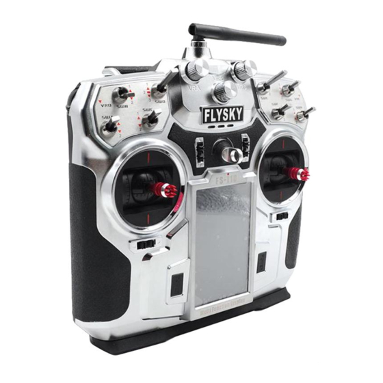
Page 8: Transmitter Overview
FS-l10 Digital proportional radio control system 2.2 Transmitter Overview VRB Knob VRA Knob VRC Knob SWE Switch SWD Switch SWB Switch SWG Switch VRD Knob VRE Knob SWA Switch SWH Switch SWF Switch SWC Switch Rudder/Aileron Rudder/Aileron Throttle/Elevator Throttle/Elevator Trim 1 Trim 3 Trim 2 Trim 4... -
Page 9: Transmitter Antenna
Note could result in damage to the wire. 2.2.2 Stick/Knob/Switch The FS-i10 has 2 gimbals, 8 switches and 5 knobs, 3 of which can be locked. • Sticks: The sticks are used for rudder, elevator, alieron and throttle control. •... -
Page 10: Stick Mode
FS-l10 Digital proportional radio control system 2.2.6 Stick Mode The system supports 4 stick modes, the default is [Mode 2]. The blue icon indicates the currently selected mode. Enter the main menu, touch the [System] icon and select your prefered mode. Mode Mode Elevator... -
Page 11: Receiver Overview
2.3 Receiver Overview i-BUS Serial Interface Status Indicator Power/Bind Port Antenna To Servos PPM Output /To Servos i-BUS Sensor Interface 2.3.1 Receiver Antenna FS-iA10B uses dual 26mm antenna and can receive and send information at the same time. Attention • Do not pull or tie the antenna or use the antenna as a servo cable. -
Page 12: Before Use
FS-l10 Digital proportional radio control system 3. Before Use Before using the product please follow the guidelines below to install the battery and connect the device. 3.1 Transmitter battery Installation Danger • Only use specified battery. Danger • Do not open, disassemble, or attempt to repair the battery. Danger •... -
Page 13: Installing Receiver And Servos
3.2 Installing Receiver and Servos Make sure that you find an appropriate location to mouth the receiver in order to, ensure performance, stability and prevent outside interference. Installation: Make sure the receiver is mounted away from motors, electonic speed controllers or any device that emmits excessive electrical noise. -
Page 14: Operation Instructions
FS-l10 Digital proportional radio control system 4. Operation Instructions Follow these guidlines to ensure proper use of your system 4.1 Power On Follow these steps to power on the system: Check the system and make sure that: • The battery is fully charged and installed properly. 。 • The receiver is off and correctly installed. -
Page 15: Preflight Inspection
4.3 Preflight Inspection Before you begin, perform the following steps to ensure the system performs as expected: 1. Check the entire system to ensure that all components function as expected. 2. Perform a distance signal test as outlined in 【9.13 Range Test】. Danger • If there are any problems during testing, no not operate the model. Danger •... -
Page 16: System Interface
FS-l10 Digital proportional radio control system 5. System Interface This chapter is an introduction to the menu and menu functions. 5.1 Home Screen The home screen displays useful information about your model, including sensors and function status etc. Transmitter Battery Model Name Status Receiver Battery... -
Page 17: Interface Quick Guide
5.1.2 Interface Quick Guide Touch this area to quickly enter the sensor selction menu; Up to 4 sensors can be displayed. To select a sensor, refer to 【9.8 Choose Sensors 】. Touch this area to quickly enter the timer menu; To set up a timer refer to 【6.23 Display Servos】. Touch this area to quickly enter the Aircraft Structure menu; To change the aircraft structure refere to 【6.25 Models】. -
Page 18: Built-In Contextual Help
FS-l10 Digital proportional radio control system 5.3 Built-in Contextual Help(Pic.1) 5.5 Reset Function Interface(Pic.3) When [ICON] is touched the system will display a The help icon is both in the title and bottom bars. Touch the left side of the bottom bar prompt: [Yes]: Select yes to return the current function or or the right side of the title... -
Page 19: Function Settings
6. Function Settings This section contains the default menu function settings. 6.1 Reverse Function (Pic.5) • At the top of the current channel, the selected endpoint and percentage are The Reverse function is Pic.5 shown. used to correct a servo •... -
Page 20: Trims
FS-l10 Digital proportional radio control system 6.4 Trims (Pic.8) • The system gives a real time readout of the channels There are 4 groups of trim Pic.8 position, not the servo switches affecting surface position. The servo will not position. Each time a Note correlate with the graph if the trim is toggled, the trim... -
Page 21: Aileron To Rudder
6.6 Aileron to Rudder (Pic.10) The aileron to rudder automatically creates a coordinated turn for the aircraft with Pic.10 aileron and rudder. The pre-programmed mix is 10% by default, meaning that if your aileron has moves to 100% of its range of movement the rudder will move 10%. If the aircraft does not have ailerons or a rudder, these function icon will not be displayed. -
Page 22: Throttle Delay
FS-l10 Digital proportional radio control system Editing Curves Pic.12 To edit a curve touch one of the points listed at the bottom of the screen then use the wheel to change its value. • This function can be set with up to 5 conditions. Setup: Activate the function by touching the function on/off icon located at... -
Page 23: Aux Channels
6.11 Aux Channels(Pic.15) 6.13 Function Delay(Pic.17) Function delay is used to slow down the response The model function allows users to set auxiliary speed of basic function output. It can be adjusted channels. Every channel that is not assigned during from 0 to 10 seconds. -
Page 24: Conditions Delay
FS-l10 Digital proportional radio control system Select low side and high side to set the limits of Setup: movement for the slave channel. For example, if Select desired channel. high side is set to 10 percent when the master Move the wheel to modify the delay time. channel is at 100% the slave will move 1/10th of its full range of motion. -
Page 25: Conditions
6.19 Logic Switches(Pic.23) Select the master, this channel/input will control the slaves output. It is also possible to select A logic switch is a switch that activates whenever stick/knob, basic functions or a channel output. certain conditions are met, for example, a light Select a slave, slaves may only be output could be programmed using a logic switch so that it channels. -
Page 26: Airplane Structure
FS-l10 Digital proportional radio control system 6.20 Airplane Structure (Pic.24) Airplane structure enables you to set the control surfaces on your model. To add or remove available surfaces first select [Modify] at the bottom right side of the screen, select each control surface available on your model so that a tick is displayed in a box next to the name. -
Page 27: Timers
These functions are also known as basic functions, as referred to in the [Trainer Mode], [Curve Mixes], [Function Delay] and [Linear mixes] sections of this user manual. Some functions can apply the function of one control surface to another, for example, the aileron function can apply aileron control to flaps and elevators. -
Page 28: Trainer Mode
This function allows you to connect 2 transmitters together using a dedicated cable connected to the back of the FS-i10. The FS-i10 that enables the trainer function will become the master, and will be able to override the other FS-i10. Usually this function is used by instructors to teach students how to fly, they can give the student full control but can quickly step in if anything goes wrong. -
Page 29: Models
of the signal. This is measured from -120dBm to -60dBm. The higher up the graph the signal appears the stronger it is, and has a bigger chance of causing interference. Along the bottom of the graph is a solid block of red, this in this case is just background noise. Background noise usually isn’t a problem and a level of background noise can be expected everywhere. - Page 30 FS-l10 Digital proportional radio control system [Copy model]: Copies the settings of a model to overwrite another model. To copy a model: Select [Copy model]. Select a copy source the setting of which will be copied. Select a target model that you wish to overwrite. Select [Yes] in the confirmation box and the target model will be overwritten by the copied model.
-
Page 31: Airplane / Glider Menu Functions
7. Airplane / Glider Menu Functions This chapter introduces airplane / glider features, in addition to features already described in the chapter 6. 7.1 Aileron Function(Pic.30) Setup: 1. Touch the box in either the [UP] or [DOWN] Pic.30 columns to select it. The aileron function enables flaps to be 2. -
Page 32: Elevator To Flap
FS-l10 Digital proportional radio control system 7.4 Elevator to Flap(Pic.33) Butterfly(Pic.35) The elevator to flap function creates a mix between The Butterfly function is used with gliders and the elevator and flaps. For example if flaps are 10% is a wing function is used when landing. Usually on the high side, when the elevator is at 100% when the butterfly function is activated the flaps movement the flap will have moved 1/10th of that... -
Page 33: Rudder Function
7.8 Rudder Function(Pic.37) V-tail(Pic.38) The rudder function is used for aircraft that have The V-tail function is used for planes that have no 2 rudders. Each rudder can set its own ratio to the elevators and has a V-tail rudder configuration. sticks movement. -
Page 34: Helicopter Menu Functions
FS-l10 Digital proportional radio control system 8.Helicopter Menu Functions This chapter introduces helicopter features, in addition to features already described in the chapter 6. 8.1 Throttle Hold(Pic.39) Setup: Throttle hold locks the 1. Activate the function by touching the function throttle to a preset on/off icon located at the bottom left of the... -
Page 35: Swashplate Mix
8.4 Swashplate Mix(Pic.42) 8.6 Hover Adjust(Pic.44) This function is used to edit the pre-programmed If your model is moving up or down, or moving in a mix control of the helicopter’s aileron, elevator and direction when hovering, use this function to correct pitch. -
Page 36: Governor
FS-l10 Digital proportional radio control system Governor(Pic.46) Pic.46 The function of a governor is to keep the head speed constant, independent of varying load on the motor. A constant RPM is a good thing for 3D flight since the cyclic and rudder functions (and gyro gain) will remain constant throughout the entire flight envelope. -
Page 37: Rx Setup
RX Setup This chapter introduces receiver features. 9.1 Bind with a Receiver This menu is for binding the transmitter and receiver. For instructions on binding, please refer to [4.2 Binding]. 9.2 RF Std This menu allows you to change the communication protocol for the transmitter. Select the protocol according to the table below: RF Standard Receiver Type... -
Page 38: Failsafe
FS-l10 Digital proportional radio control system 9.6 Failsafe (Pic.50) This function is used to protect the models and users, if the receiver loses signal and therefore is no longer controllable. All channels are listed in the failsafe menu. [Off] means that in case of a loss of signal, the corresponding servo will keep its last received position. -
Page 39: Choose Sensors
9.8 Choose Sensors The main screen can display the value of up to 4 sensors. This function is used to select which sensors to display. To choose a sensor: Select a slot, 1, 2, 3 or 4. Any sensors that are connected will automatically populate this list. Select the desired sensor and exit the function. -
Page 40: Range Test
After selecting [Update receiver], the FS-i10 will ask for a conformation. Select [Yes]. • If the FS-i10 has an update for the receiver, the update will be displayed as a percentage. when the update is complete the function will exit automatically. -
Page 41: System Settings
10.8 USB Function The system can be used with various computer based simulators via USB. Setup: 1. To enable the simulator function select [FS-i10 emulator] from the menu. 2. To disable this function select [None]. • When the emulator mode is active, the system cannot transmit data wirelessly. -
Page 42: Firmware Update
10.11 Factory Reset To reset the system to its factory settings press this option, then select [Yes] to confirm. 10.12 About FS-i10 This option contains basic information about the system such as currents hardware and software versions and the TX ID. -
Page 43: Product Specification
11. Product Specification This section contains the FS-i10, FS-iA10B and sensor specifications. 11.1 Transmitter Specification (FS-i10) Channels Model type Fixed-Wing/Glider/Helicopter RF range 2.408 ~ 2.475 GHz Bandwidth 500 KHz Band RF power Less then 20 dBm 2.4G system AFHDS 2A Code type... -
Page 44: Sensor Specification
FS-l10 Digital proportional radio control system 11.3 Sensor Specification 11.3.1 RPM Telemetry (Magnetic) Module(FS-CPD01) Model type Car/Boat/Plane Speed range 0 to 60000 rpm Power input 4.0 to 6.5 V DC Weight 6.6g Dimension (Length x Width x Height) 31*15*8.5 mm Color Black 11.3.2 RPM Telemetry... -
Page 45: I-Bus Receiver(Fs-Cvt01)
11.3.6 i-Bus Receiver(FS-CEV01) Model type Car/Boat/Plane Power input 4.0 to 6.5 V DC Weight Dimension (Length x Width x Height) 32*15.6*7.5mm Color Black i-Bus port Channels 11.3.7 i-Bus Receiver(FS-CEV02) Model type Car/Boat/Plane Power input 4.0 to 6.5 V DC Weight 7.6 g Dimension (Length x Width x Height) 32*16*10 mm... -
Page 46: Appendix 1 Fcc Statement
FS-l10 Digital proportional radio control system Appendix 1 FCC Statement This equipment has been tested and found to comply with the limits for a Class B digital device pursuant to part 15 of theFCC rules. These limits are designed to provide reasonable protection against harmful interference in a residential installation. - Page 47 http://www.flysky-cn.com Copyright ©2013-2017 Flysky RC model technology co., ltd Edition:2016-06-06...