Table of Contents
Advertisement
Quick Links
This document is "OKI DATA – CONFIDENTIAL"
Only persons and parties authorised by OKI DATA have
permissions to access this document.
This document should not be accessed by any parties
without the approval of OKI DATA.
Anyone who is found to be contradicting the above may be subject to legal action.
OEL
Maintenance Manual
B412/B432/B512
ES4132/ES5112
Revision 1
31 Oct 2014
Advertisement
Table of Contents
Troubleshooting

Related Manuals for Oki ES5112dn


Summary of Contents for Oki ES5112dn
- Page 1 This document is “OKI DATA – CONFIDENTIAL” Only persons and parties authorised by OKI DATA have permissions to access this document. This document should not be accessed by any parties without the approval of OKI DATA. Anyone who is found to be contradicting the above may be subject to legal action.
- Page 2 Document Revision History Corrected items Person in Rev.No Date Corrected items charge Person in Page Description of change Rev.No Date charge Page Description of change 2014-10-31 Issue P1E18 H.Hayashi...
- Page 3 Note! • Manual may be revised and updated at any time without notice. • Unexpected mistakes may exist in the manual. OKI will not assume any responsibility whatsoever for damage to the equipmentrepaired/adjusted/changed by the user etc with this manual.
-
Page 4: Table Of Contents
Contents Index 1. CONFIGURATION ..............1-1 3.1.5 Factory Maintenance Menu (For a factory) ..........3-9 3.1.6 Self-diagnostic Mode (Engine Maintenance Mode) .........3-10 1.1 System configuration ..................1-2 3.1.6.1 Operation panel ................3-10 1.2 Structure of Printer ....................1-3 3.1.6.2 Ordinary self-diagnostic mode (level 1) ..........3-13 1.3 Offer of Options ....................1-5 3.1.6.2.1 How to enter the self-diagnostic mode (level 1) ......3-13 1.4 Specifications ....................1-6... - Page 5 Contents 4.2.14 Stacker Cover ..................4-16 4.2.15 Fuser Assy ....................4-17 4.2.16 MPT Assy ....................4-18 4.2.17 Cover Assy Rear ..................4-19 4.2.18 Guide Eject Lower Assy................4-20 4.2.19 Eject Motor ....................4-21 4.2.20 Plate Side R Assy / Plate Side L Assy / Front Assy .........4-22 4.2.21 Plate Side L Assy ..................4-23 4.2.22 Plate Side R Assy ..................4-24 4.2.23 Roller Regist ....................4-25...
-
Page 6: Configuration
CONFIGURATION 1.1 System configuration ..............1-2 1.2 Structure of Printer ..............1-3 1.3 Offer of Options ................1-5 1.4 Specifications ................1-6 1.5 Interface specifications ..............1-9... -
Page 7: System Configuration
1. CONFIGURATION 1.1 System configuration System Configuration of the Printer Unit As the diagram 1.1 shows, for the standard configuration printer is configured by controller unit and engine unit. Wireless LAN module * USB 2.0 (10BASE-T/100BASE-TX/GigaBit Ether) Entrance sensor Write sensor Operator panel board Faceup stacker open sensor... -
Page 8: Structure Of Printer
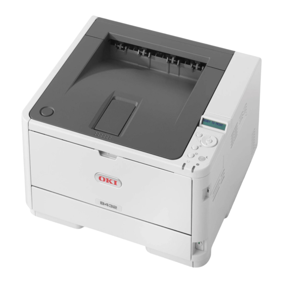
1. CONFIGURATION 1.2 Str ucture of Printer The printer main unit includes the following hardware parts. • Electrophotographic processing part • Paper feeding part • Controller • Operational part • Power supply unit B412dn/B432dn/ES4132dn Note! • Fuser-Assy has to be replaced by Assy unit. •... - Page 9 1. CONFIGURATION B512dn/ES5112dn Figure1-3...
-
Page 10: Offer Of Options
1. CONFIGURATION 1.3 Offer of Options This product can be installed with the following option. (1) Second Tray Unit (2) Wireless LAN... -
Page 11: Specifications
1. CONFIGURATION 1.4 Specifications Item B412dn B432dn/ES4132dn B512dn/ES5112dn Item B412dn B432dn/ES4132dn B512dn/ES5112dn (DT Low speed (DT High speed (DT High speed, (DT Low speed (DT High speed (DT High speed, model) model) 530 sheet model) model) model) 530 sheet model) - Page 12 B412dn/B432dn/B512dn : Approx. 2,000 pages (company Standby 30dBA toner standard) Power Background level ES4132dn/ES5112dn : Approx. 9,700 pages (@5% duty) save mode Supplies B412dn : 3,000 pages / 7,000 pages (@ISO19752) Power Deep sleep 1.4W B432 / B512 : 3,000 pages / 7,000 pages / 12,000 pages...
- Page 13 1. CONFIGURATION Item B412dn B432dn/ES4132dn B512dn/ES5112dn (DT Low speed (DT High speed (DT High speed, model) model) 530 sheet model) Transfer roller life Equal to printer Life Fuser life Equal to printer Life Print Function Quiet mode Toner save mode...
-
Page 14: Interface Specifications
1. CONFIGURATION 1.5 Interface specifications 1.5.1 USB Interface Specification (2) Cable Cable length : Specification Cable of USB2.0 spec. of less than 5m.(less 1.5.1.1 Outline of USB Interface than 2m is recommended) (1) Basic Specification 1.5.1.3 USB Interface Signal (2) Transmission Mode Name of Single Function Hi speed (480Mbps±0.05% max.) -
Page 15: Network Interface Specification
1. CONFIGURATION 1.5.2 Network Interface Specification 1.5.2.3 Network Interface Signal Pin No. Signal name Functions 1.5.2.1 Network Interface Basic Specification TRD+(0) Transmit and receive Data 0 (+) TRD-(0) Transmit and receive Data 0 (-) Network Protocol ・TCP/IP related TRD+(1) Transmit and receive Data 1 (+) TRD+(2) Transmit and receive Data 2 (+) 1.5.2.2 Network Interface Connector and Cable... -
Page 16: Wireless Lan Interface (Option)
1. CONFIGURATION 1.5.3 Wireless LAN Interface (Option) 1.5.3.1 Outline of Wireless LAN (1) Specification IEEE 802.11a/b/g/n (2.4GHz/5GHz) (2) Power supply voltage (3) Printer side interfaces USB Port Note! In using wireless LAN, don't connect a LAN cable to this product. 1-11... -
Page 17: Procedures For Repairing
PROCEDURES FOR REPAIRING Troubleshooting .................2-2 Points to be checked before modifying printing problems ..2-2 Points to be checked when the printing problems are modified ...2-2 Preparation for Troubleshooting ..........2-3 Troubleshooting Flow ..............2-4... -
Page 18: Troubleshooting
2. Procedures for Repairing 2.1 Troubleshooting (1) Check “Troubleshooting” of the user’s manual. (2) Collect the information of the status at the failure as much as possible. (3) Inspect the device in the status similar to the status at the failure occurrence. 2.2 Points to be checked before modifying printing problems (1) Check that the printer is used in appropriate environment conditions. -
Page 19: Preparation For Troubleshooting
(1) Display of the operator panel The failure status of the printer is displayed don the LCD of the operator panel. Take an appropriate action as instructed by the messages displayed on LCD. B412dn/B432dn/B512dn/ES4132dn/ES5112dn On-line button Power save button Cancel button... -
Page 20: Troubleshooting Flow
2. Procedures for Repairing 2.5 Troubleshooting Flow 2.5.1 LCD Status Message/ Trouble Table If there are failures in the printer, troubleshooting is per formed according to the following process flow. Troubles and statuses possible to be displayed on LCD are outlined in Troubles Table 2-1. - Page 21 2. Procedures for Repairing Status level Error code Status level Error code Function Function Ready Atten Ready Atten Initializing FLASH FORMAT Off Displays that Flash memory is Normal READY TO PRINT Off Shows on-line status. being formatted. Normal OFFLINE Off Shows off-line status. It is displayed it when Resident * Ready LED in off-line is always Flash memory not fomented are...
- Page 22 2. Procedures for Repairing Status level Error code Status level Error code Function Function Ready Atten Ready Atten Normal CANCELING JOB Blink Varies Indicates a job being cancelled This should be appeared □ (USER DENIED) due to no print permit. (Related to FOR MAXIMUM after the toner/drum/ JobAccount)
- Page 23 2. Procedures for Repairing Status level Error code Status level Error code Function Function Ready Atten Ready Atten Warning Varies On The thing that the toner empties is Warning Varies On %TRAY%: The tray is empty. TONER EMPTY shown.
- Page 24 An identifier to automatically after 3 seconds. Error type (For details, see the %INFO% is contained in the overview chapter.) consumable tag. [ OKI Original] %FS_ERR% = 0 … GENERAL ERROR Warning PRESS ONLINE SW Varies Varies Memory overflow was occurred in = 1 …...
- Page 25 2. Procedures for Repairing Status level Error code Status level Error code Function Function Ready Atten Ready Atten Warning PRESS ONLINE SW Varies Varies Invalid data was received. Press Error LOAD %MEDIA_SIZE%/ Blink The media type in the tray and INVALID DATA the On-line switch and eliminate %MEDIA_TYPE% AND...
- Page 26 2. Procedures for Repairing Status level Error code Status level Error code Function Function Ready Atten Ready Atten Error LOAD %MEDIA_SIZE%/ Blink The size of paper or media type in Error NETWORK CONFIG Varies Varies This appears during the NIC %MEDIA_TYPE% the tray does not match the print (ONLINE)
- Page 27 2. Procedures for Repairing Status level Error code Status level Error code Function Function Ready Atten Ready Atten Error LOAD %MEDIA_SIZE% Blink Printing request is issued to an Error REPLACE TONER Blink It is a toner besides our %ERRCODE%:%TRAY% empty tray. %ERRCODE%: specification.
- Page 28 2. Procedures for Repairing Status level Error code Status level Error code Function Function Ready Atten Ready Atten Error OPEN UPPER COVER Blink Paper jam occurred during paper Error REBOOTING Rebooting of the controller unit. %ERRCODE%:PAPER feeding from tray. %CODE% (Off) %CODE% is a decimal value (one Error 391 : TRAY1...
-
Page 29: Service Call List
2. Procedures for Repairing 2.5.2 Service Call List Display Cause Error details Measure POWER OFF/ON Video error. Is the CU/PU installed Reinstall it properly. Display Cause Error details Measure 075:ERROR ** An error was properly? Replace it. detected in POWER OFF/ON Turn off and on the expanding 002:ERROR... - Page 30 2. Procedures for Repairing Display Cause Error details Measure Display Cause Error details Measure SERVICE CALL Ambient Is the cable from the CU/PU Re-connect it properly. SERVICE CALL Toner sensor Is the toner cartridge Install the toner 123:ERROR humidity board to the toner sensor Replace the toner 163:ERROR detection...
-
Page 31: Lcd Message Troubleshooting
2. Procedures for Repairing 2.5.3 LCD Message Troubleshooting Display Cause Error details Measure SERVICE CALL TAG Reader If you still have trouble even after using the LCD Status Message/ Trouble 230:ERROR not installed List, follow the troubleshooting flowchart displayed below to solve the SERVICE CALL TAG interface IA TAG interface error was... - Page 32 2. Procedures for Repairing The case where the printer does not work normally after tuning on the power • Turn off the power and then, turn on the power again. • No Do Power switch LED blinking rapidly? • Are messages in the display of LCD all in black? •...
- Page 33 2. Procedures for Repairing [Jam Error] -1 Paper feed jam (Error 390)(Error 391)(Error 392) • No Does the paper feed clutch work normally? • Yes Replace the paper feed roller and shaft. • Does a jam error occur when turning on the power? •...
- Page 34 2. Procedures for Repairing [Jam Error] • No Does the main drum motor rotate? -2 Running jam (Error 380)(Error 381) • No Is the DM connector of the main board connected appropriately? • Does a jam error occur when turning on the power? •...
- Page 35 2. Procedures for Repairing [Jam Error] Paper Size Error (Error 400) -3 Ejection Jam (Error 382) • Is the paper which is specified size used? • Does an ejection jam error occur when turning on the power? • No Use a specified-size paper. •...
- Page 36 2. Procedures for Repairing Fuser unit Assy (Error 170) (Error 171) (Error 172) (Error 173) Interface Error (Error 182) • Is the thermistor connector inserted into the THERM connector of the • Is the Second Tray unit used? main board normally? •...
- Page 37 2. Procedures for Repairing -1 Fuser Fan Error (Error 127) • Is the exhaust fan rotating? • Yes Replace the main board. • No Is the CN2 connector of the high-voltage power supply unit connected to the board properly? •No Connect the CN2 connector appropriately.
-
Page 38: Print Troubleshooting
2. Procedures for Repairing 2.5.4 Print Troubleshooting The troubleshooting procedure of abnormal printing is described as follows. The typical abnormal printing is shown in the following Figure 2-2. Trouble Flowchart number Pale printing or the whole printing is faded. (Fig.2-2 Pale printing or The white section The white section is dirty. - Page 39 2. Procedures for Repairing Pale printing or the whole printing is faded. • Does the printer lack toner? (Is the message of Toner Low displayed?) • Has the trouble been solved? • Yes Supply the toner. • Yes Completed • No Is specified paper used.
- Page 40 2. Procedures for Repairing The white section is dirty White paper is outputted • Is the image drum exposed by the external light? • Is the LED head appropriately connected? (Check the HEAD0 connector of the main board and the PC connector of the LED head.) •...
- Page 41 2. Procedures for Repairing Periodic failure In case of error printing Cycle Handling • Does the contact plate of the transfer roller contact the TR terminal of the high-voltage power supply unit properly? (See Figure 2-4 , Image Drum 94.25mm Replace or clean the image drum cartridge.
- Page 42 2. Procedures for Repairing In case of inefficient fusing (If touch by hand the character or image that are Vertical white belt/ White line printed on paper will be faded or unstuck.) • Is the LED lens dirty? • Is the specified paper used? •...
- Page 43 2. Procedures for Repairing Transfer roller Frame-Assy-TR Fuse Contact plate for transfer High voltage power supply board TR terminal Fuse Contact plate for transfer Figure 2-3 Figure 2-4 2-27...
- Page 44 2. Procedures for Repairing Fuser Assy Contact plate Figure 2-5 2-28...
-
Page 45: Adjustment
ADJUSTMENT This chapter provides explains relating to the adjustment that is necessary while replacing part. Adjustment is performed by modifying the value of parameter that is set on the EEPROM of main PCB board. Parameter can be set by key operation that is from the operator panel. -
Page 46: Category And Function Of Maintenance Mode
3. ADJUSTMENT 3.1 Category and function of maintenance mode •Maintenance mode includes the following. Category Item Value Default Function / Notes - "Admin Menu" and "Boot Menu" which is shown by an end user. ADMIN PANEL NEARLIFE LED ENABLE Sets up LED lighting control - "Service Menu"... - Page 47 3. ADJUSTMENT Category Item Value Default Function / Notes Category Item Value Default Function / Notes ADMIN OTHERS RECEIVE AUTO Sets the size of receive ADMIN OTHERS FLASH FORMATTING PCL Formats a specified partition. SETUP SETUP SETUP BUF SIZE 0.1 MB buffer SETUP SETUP...
- Page 48 3. ADJUSTMENT Category Item Value Default Function / Notes Category Item Value Default Function / Notes ADMIN OTHERS LANGUAGE LANG EXECUTE Initialize the message file ADMIN OTHERS DISPLAY Specify the timeout of Job SETUP SETUP SETUP INITIALIZE loaded in FLASH. SETUP SETUP TIMEOUT...
- Page 49 3. ADJUSTMENT Category Item Value Default Function / Notes ADMIN SETTINGS RESTORE MENU EXECUTE – Changes to the menu SETUP setting saved. When the Enter switch is pressed, the following confirmation message appears. ARE YOU SURE? YES/NO If NO is selected, the previous menu display resumes.
-
Page 50: Boot Menu
3. ADJUSTMENT 3.1.2 Boot Menu Category Item Value Default Function / Notes To enter Boot menu,you should holding on the "OK" button as the same time as BOOT MENU LOCKOUT ENABLE Set On/Off of Menu Lockout MENU DISABLE function the power is turned on. On: Menus exept for "Print A password the same as Admin menu is necessary for "BOOT MENU". -
Page 51: Service Menu (The Member Of Maintenance)
3. ADJUSTMENT 3.1.3 Service Menu (The member of maintenance) Category Item Value Default Function / Notes This menu is used for only a member of maintenance, and it is not shown to an SERVICE DRUM When drum extend life is MENU NEARLIFE 1000... -
Page 52: System Maintenance Menu (The Member Of Maintenance)
3. ADJUSTMENT 3.1.4 System Maintenance Menu (The member of maintenance) Category Item Value Default Function / Notes This menu is used for only a member of maintenance, and it is not shown to an FUSE KEEP EXECUTE It will be ONLINE by pressing end user. -
Page 53: Factory Maintenance Menu (For A Factory)
3. ADJUSTMENT 3.1.5 Factory Maintenance Menu (For a factory) Category Item Value Default Function / Notes This menu is used for a factory, and it is not shown to an end user. FAC MAINTE PERSONALITY XPS ENABLE Changes the default of Support MENU DISABLE PDL per brand. -
Page 54: Self-Diagnostic Mode (Engine Maintenance Mode)
3. ADJUSTMENT 3.1.6 Self-diagnostic Mode (Engine Maintenance Mode) (1) How to select the menu items Self-diagnostic mode Menu items can be selected directly. XXXXX layout (overall) (1) To enter Self-diagnostic mode, turn on the power switch while holding XXXXX Menu items can be selected by pressing either [MENU ] or [MENU ] key. - Page 55 3. ADJUSTMENT (1) How to select the menu items LEVEL0 XXXX Menu items can be selected by long pressing of [ ] or [ONLINE], or by short pressing of [MENU ] or [MENU ]. Menu items can be entered by pressing of [OK] or [ ], and can be selected by pressing of [MENU ] or [MENU ]. XXXX Engine status display [ ] (2 Sec)
- Page 56 3. ADJUSTMENT (1) How to select the menu items Menu items can be selected by pressing either [MENU ] or [MENU ] key, and executed by pressing [OK]. LEVEL1 XXXXX Menu items can be entered by pressing of [OK] or [ ], and can be selected by pressing of [MENU ] or [MENU ]. XXXXX The test can be executed by pressing [OK], and can be exited by pressing [ ].
-
Page 57: Ordinary Self-Diagnostic Mode (Level 1)
3. ADJUSTMENT 3.1.6.2 Ordinary self-diagnostic mode (level 1) 3.1.6.2.1 How to enter the self-diagnostic mode (level 1) Menu items of the ordinary self-diagnostic mode are shown below. While pressing the [MENU ] and [MENU ] keys simultaneously, turn on the power to enter the system maintenance mode. -
Page 58: Switch Scan Test
3. ADJUSTMENT 3.1.6.3 Switch scan test This self-diagnostic menu is used to check the entry sensor and the switch. Enter the self-diagnostic mode (level 1), press the [MENU ] or [MENU Face down stacker Eject Assy opening repeatedly ,and press the [OK] key when the "SWITCH SCAN" is displayed in Entrance Stacker Cover -closing sensor... - Page 59 3. ADJUSTMENT Table 3-3 SWITCH SCAN details <Item having no function> Asterisk mark (*) is displayed in the lower row of display area. * 1: “L” is displayed when the cover is opened. Display area, Display Display Display Display upper row Details area, Details...
-
Page 60: Motor Clutch Test
3. ADJUSTMENT 3.1.6.4 Motor clutch test Registration roller 2nd eject roller Image drum Heat roller This self-diagnostic menu is used to test the motor and clutch. feed roller 1. Enter the self-diagnostic mode (level 1), press the [MENU ] or [MENU Main motor (DC motor) -
Page 61: Test Print
3. ADJUSTMENT 3.1.6.5 Test print Display Setting value Function PRINT EXECUTE – Pressing the [OK] key starts print/Pressing the This self-diagnostic menu is used to print the test pattern that is built inside PU. Other test CANCEL key terminates print. (In units of page) patterns are stored in the controller. - Page 62 3. ADJUSTMENT While the message "PRINT EXECUTE" that is set by the operation specified in • Displays are switched by pressing the [MENU key. step 2 is being displayed, press the [OK] key and the test print is executed with T=*** U=***[###] the setting value that has been set by steps 2 and 3.
-
Page 63: Consumable Item Counter Display
3. ADJUSTMENT 3.1.6.6 Consumable item counter display • Displays are switched by pressing the [MENU key. This self-diagnostic menu is used to display the consumption status of the consumable DB:k** items. Enter the self-diagnostic mode (level 1), press the [MENU ] or [MENU repeatedly ,and press the [OK] key when the "CONSUMABLE STATUS"... -
Page 64: Number Of Print Copies Counter Display
3. ADJUSTMENT 3.1.6.7 Number of print copies counter display 3.1.6.8 Switching between the Factory mode and the Shipping mode This self-diagnostic menu is used to display status of the number of copies of a printer. This self-diagnostic menu item is used to switch between the Factory mode and the Shipping mode. -
Page 65: Self-Diagnostic Function Setting
3. ADJUSTMENT 3.1.6.9 Self-diagnostic function setting Operation at the Display Setting value Function setting value This self-diagnostic menu is used to set valid/invalid of the error detection by the various TONER SENSOR ENABLE Detects Valid/Invalid of toner sensor sensors. operation. DISABLE Not to detect The error detection can be made invalid or valid for locating source of abnormality. -
Page 66: Led Head Serial Number Display
3. ADJUSTMENT 3.1.6.10 LED head serial number display This self-diagnostic menu item is used to check whether the downloaded LED head data matches the serial number of the actual LED head. Enter the self-diagnostic mode (level 1), press the [MENU ] or [MENU repeatedly ,and press the [OK] key when the "LED HEAD DATA"... -
Page 67: Energy Conservation Mode Setting
3. ADJUSTMENT 3.1.7 Energy conservation mode setting 3.1.8 EEPROM Initialization This printer is equipped with two types of energy conservation mode, MODE1 The treatment for EEPROM Initialization at each phenomenon is displayed as "NORMAL MODE" and MODE2 as "ECO MODE." as Diagram 3-1. -
Page 68: Adjustment At Part Replacement
3. ADJUSTMENT 3.2 Adjustment at part replacement Adjustment is necessary while replacing the following part. Replacing part Adjustment Main PCB board EEPROM data upload / download 3.2.1 EEPROM data upload / download method In the case of replacing the Print Board of Controller, copy the old EEPROM content to the new EEPROM of new board and then save the customer setting. -
Page 69: Replacement Of Parts
REPLACEMENT OF PARTS This chapter describes the procedures of the field replacement of parts, assemblies and units. The procedures are to detach them. Reverse the procedures to attach them. The reference part numbers used in this manual (such as ) do not identical to the part numbers in the maintenance disassembly configuration diagram 45762001TL and the RSPL 45762001TR. -
Page 70: Preparation For Parts Replacement
4. REPLACEMENT OF PARTS 4.1 Preparation for parts replacement This section explains the replacement procedure of part, assembly, and unit (2) Do not disassemble the printer in the case of normal operation. in the working place. Disassembling procedure relating to reassembling is (3) Do not disengage the part that there is not any necessary to touch. -
Page 71: Maintenance Tools
4. REPLACEMENT OF PARTS [Maintenance tools] Table 4-1-2 shows the tools necessary to use Maintenance Utility software. The necessary tools for replacing the print circuit board, assembly, and unit is shown as graph 4-1-1. Table 4-1-2: Maintenance Tools Maintenance Tool Quantity Remarks Graph 4-1-1 Maintenance tools... -
Page 72: Parts Replacement Procedure
4. REPLACEMENT OF PARTS 4.2 Parts replacement procedure This section describes the procedure for replacing the parts and assemblies shown in the disassembly diagrams below. 4.2.1 LED Head (1) Open the Stacker Cover. (2) Remove the ID UNIT. (3) Disengage the tab of the Holder-Head from the stacker cover by using a flat-head screwdriver or something. -
Page 73: Roller-Transfer
4. REPLACEMENT OF PARTS 4.2.2 Roller-Transfer (1) Open the Stacker Cover. (2) Remove the ID UNIT. ① (3) Take the Frame-Assy-TR out of the printer. ③ ② (4) Disengage the latches of Bearing-TR ① on both ends. (5) Hold the Bearing-TR ① on the both side, and then lift up the Roller- Spring Transfer ②... -
Page 74: Duplex Belt
4. REPLACEMENT OF PARTS 4.2.3 Duplex Belt (1) Take out the Frame-Assy-TR. (Refer to 4.2.2) (2) Remove the cassette and place the printer unit with its right side down. ② (3) Remove the E-ring ① and slide the Shaft-Dup-Clutch in the direction of ③... -
Page 75: Cover-Side-R / Cover-Lower-R (B512 Only)
4. REPLACEMENT OF PARTS 4.2.4 Cover-Side-R / Cover-Lower-R (B512 only) *The next step is B512 only. (7) Insert the Minus Driver into the hole B of Guide-Cassette-R and disengage (1) Remove the cassette. the five tabs and remove the Cover-Lower-R ④ in the direction of the (2) Open MPT, the Cover-Assy-Stacker and the Cover-Assy-Rear. -
Page 76: Cover-Side-L / Cover-Lower-L (B512 Only)
4. REPLACEMENT OF PARTS 4.2.5 Cover-Side-L / Cover-Lower-L (B512 only) *The next step is B512 only. (5) Insert the Minus Driver into the hole B of Guide-Cassette-L and disengage (1) Remove the cassette. the five tabs and remove the Cover-Lower-L ② in the direction of the (2) Open MPT, the Cover-Assy-Stacker and the Cover-Assy-Rear. -
Page 77: Cu-Board
4. REPLACEMENT OF PARTS 4.2.6 CU-Board (3) Disconnect the all cables. (4) Remove the screw (Silver : Small) ③ , remove the two screw (Silver) ④ (1) Remove the Cover-Side-R. (Refer to 4.2.4) and remove the CU-Board ⑤ . (2) Remove the seven screws (Silver) ① . Remove the Plate-Shield ② . (5) Remove the two screws (Silver) ⑥... -
Page 78: Power Supply Unit
4. REPLACEMENT OF PARTS 4.2.7 Power Supply Unit Warning Risk of Electric Shock There is a risk of electric shock during replacement of the low voltage power supply. Use insulating gloves or avoid direct contact with any conducting part of the power supply, and caution should be exercised during replacement. -
Page 79: Dc Motor
4. REPLACEMENT OF PARTS 4.2.8 DC Motor (1) Remove the Plate-Shield. (Refer to 4.2.6) (2) Remove the Power Supply Unit ( Board ) and Sheet-Insulation-LV.(Refer to 4.2.7) (3) Disconnect the cable and remove the screw(Silver) ① , remove the Switch-Assy ② . (4) Remove the screw(Silver) ③... -
Page 80: Hopping / Mpt / Regist Clutch
4. REPLACEMENT OF PARTS 4.2.9 Hopping / MPT / Regist Clutch (1) Remove the CU-Board. (Refer to 4.2.6) (2) Remove the Power-Supply Unit ( Board ). (Refer to 4.2.7) (3) Remove the DC Motor. (Refer to 4.2.8) (4) Remove the Sheet-Insulation-CU ① . (5) Remove the two screws (Silver) ②... -
Page 81: Hv-Board / Motor-Fan
4. REPLACEMENT OF PARTS 4.2.10 HV-Board / Motor-FAN (1) Remove the Cover-Side-L. (Refer to 4.2.5) (2) Remove the screw (Black) ① and the four screws (Silver) ② , disengage the two tabs (a and b), and remove HV-Board ③ . Be careful not to lose Spring-Contact ④... -
Page 82: Cover Assy Ope
4. REPLACEMENT OF PARTS 4.2.11 Cover Assy OPE 4.2.12 Ope PCB Assy (1) Remove the Cover-Side-R and Cover–Side-L. (Refer to 4.2.4 / 4.2.5) (1) Remove the Cover Assy Ope. (Refer to 4.2.11) (2) Remove the two screws (Black) ① . (2) Remove the Plate-Shield. -
Page 83: Cover Assy Stacker
4. REPLACEMENT OF PARTS (6) Remove the Cover Assy Stacker ⑥ and two Spring-Torsion-ST ⑦ , ⑧ . 4.2.13 Cover Assy Stacker (7) Assembling is performed by the reverse procedure with removing. (1) Remove the Cover-Side-R and Cover–Side-L. (Refer to 4.2.4 / 4.2.5) (Note on removing / assembling) (2) Remove the Plate-Shield. -
Page 84: Stacker Cover
4. REPLACEMENT OF PARTS 4.2.14 Stacker Cover (1) Remove the Cover Assy Stacker. (Refer to 4.2.13) (2) Remove the LED Head. (Refer to 4.2.1) (3) Remove the four screws (Black) ② , remove the Cover-Lever ③ . ④ , Lever-Lock-Button ⑤ (4) Remove the Lever-Lock-Top . -
Page 85: Fuser Assy
4. REPLACEMENT OF PARTS 4.2.15 Fuser Assy Note! Replace the Fuser-Assy by Assy unit. It is forbidden for disassembling the Fuser-Assy, also, reusing the disassembled Fuser-Assy. ④ (1) Take out the Frame-Assy-TR. (Refer to 4.2.2) (2) Remove the Cover Assy Stacker. (Refer to 4.2.13) (3) Remove the two screws (Silver) ①... -
Page 86: Mpt Assy
4. REPLACEMENT OF PARTS 4.2.16 MPT Assy (1) Remove the Cover-Side-R and Cover–Side-L. (Refer to 4.2.4 / 4.2.5) ① (2) Remove the Switch-Assy.(Refer to 4.2.8) (3) Remove the Cover-Assy-OPE. (Refer to 4.2.11) (4) Remove the two screws (Silver) ① Plate-Front ② . . -
Page 87: Cover Assy Rear
4. REPLACEMENT OF PARTS (6) Remove the two screws (Black) ④ and separate Cover-Rear ⑤ and 4.2.17 Cover Assy Rear Guide-Eject-Upper-Assy ⑥ . (1) Remove the Cover-Side-R and Cover–Side-L. (Refer to 4.2.4 / 4.2.5) (7) Remove the Gear-Idle ⑦ . (2) Remove the CU-Board. -
Page 88: Guide Eject Lower Assy
4. REPLACEMENT OF PARTS 4.3.18 Guide Eject Lower Assy (1) Remove the Cover-Side-R and Cover–Side-L. (Refer to 4.2.4 / 4.2.5) (2) Remove the CU-Board. (Refer to 4.2.6) (3) Remove the Sheet-Insulation-CU. (Refer to 4.2.9) (4) Remove the Cover-Eject. (Refer to 4.2.13) ①... -
Page 89: Eject Motor
4. REPLACEMENT OF PARTS 4.2.19 Eject Motor (1) Remove the Cover-Side-R and Cover–Side-L. (Refer to 4.2.4 / 4.2.5) (2) Remove the CU-Board. (Refer to 4.2.6) (3) Remove the Cover Assy Stacker. (Refer to 4.2.13) (4) Remove the Fuser Assy. (Refer to 4.2.15) (5) Remove the Cover Assy Rear. -
Page 90: Plate Side R Assy / Plate Side L Assy / Front Assy
4. REPLACEMENT OF PARTS 4.2.20 Plate Side R Assy / Plate Side L Assy / Front Assy (1) Remove the Cover-Side-R and Cover–Side-L. (Refer to 4.2.4 / 4.2.5) (2) Remove the CU-Board. (Refer to 4.2.6) (3) Remove the Power Supply Unit. (Refer to 4.2.7) ②... -
Page 91: Plate Side L Assy
4. REPLACEMENT OF PARTS 4.2.21 Plate Side L Assy (1) Separate the Plate Side L Assy. (Refer to 4.2.20) (2) Remove the four screws (Silver) ① Guide-Cassette-L ② and ⑧ . Remove the Spring-Lock-Cassette ③ . ⑩ (3) Remove Lever-Sensor Cassette ④ and Spring-Sensor ⑤ from the Guide- ⑨... -
Page 92: Plate Side R Assy
4. REPLACEMENT OF PARTS 4.2.22 Plate Side R Assy (1) Separate the Plate Side R Assy. (Refer to 4.2.20) (2) Remove the two screws (Silver) ① Guide-Cassette-R ② . ② . Remove the ① (3) Remove the two screws (Black) ③ . -
Page 93: Roller Regist
4. REPLACEMENT OF PARTS 4.2.23 Roller Regist 4.2.24 Roller Feed Assy (1) Separate the Front Assy. (Refer to 4.2.20) (1) Separate the Front Assy. (Refer to 4.2.20) (2) Remove the two screws (Black) ① and Plate-Feed-B ② . (2) Remove the two screws (Black) ① and Plate-Feed-B ② . (Be careful not to lose the gear that is removed with the plate.) (Be careful not to lose the gear that is removed with the plate.) (3) Remove the Gear-Idle-MPT ③... -
Page 94: Lever In Sensor / Lever Wr Sensor / Photo Interrupter
4. REPLACEMENT OF PARTS 4.2.25 Lever In Sensor / Lever WR Sensor / Photo Interrupter (1) Separate the Front Assy. (Refer to 4.2.20) ⑦ (2) Separate the Roller-Pressure and Roller Regist. (Refer to 4.2.23) (3) Remove the two screws (Black) ① the Holder-Sensor ②... -
Page 95: Paper Feeding Roller (Roller-Pick-Up,Roller-Feed-Now)
4. REPLACEMENT OF PARTS 4.2.26 Paper feeding roller (Roller-Pick-Up,Roller-Feed-NOW) (3) As pushing the tab downward, open the cover (black) that is on the left of the feed roller ② . • In the case of Tray 1 (4) Pull out the feed roller ② downward. (1) Turn off the printer and pull out the paper cassette tray. -
Page 96: Paper Feeding Roller(Roller-Assy-Mpt)/Paper Feeding Sub Roller
4. REPLACEMENT OF PARTS 4.2.27 Paper feeding roller(Roller-Assy-MPT)/Paper feeding sub roller (1) Turn off the printer. (2) Open the multipurpose tray. (3) Open the Lever-Link ① and feed roller cover ② . (4) Remove the feed sub roller ③ by rotating it toward you. (5) Open the feed roller cover ④... -
Page 97: Frame-Assy-Retard , Spring-Retard
4. REPLACEMENT OF PARTS 4.2.28 Frame-Assy-Retard , Spring-Retard (1) Remove the cassette. (2) Open the Retard-Cover by pushing two tabs in the directions of the arrows. (3) Remove Frame-Assy-Retard ① by pushing it in the direction of the arrow. (Spring-Retard ② is removed together.) (4 ) Assembling is performed by the inverse procedure with removing. -
Page 98: Lubricating Points
4. REPLACEMENT OF PARTS 4.3 Lubricating points This subsection indicates the lubricating points of the printer. Conversely, it means that any other parts than the specified lubricating points must not be lubricated. There is no need to lubricate in the midst of a disassembling job. However, if lubricating oil has been wiped off, supply the specified oil. - Page 99 4. REPLACEMENT OF PARTS Plate-Assy-Side-L -1 Plate-Assy-Side-R EM-30LP Class C Apply a normal amount of MOLYKOTE (EM-30LP) to the hatched areas. (Shaft end surface side) Plate-ID-Gear (Caulking) C-9300 or C-5005 Class A Apply a normal amount of Tetra (C-9310 or C-5005) to the hatched areas. (Contact surface) 4-31...
- Page 100 4. REPLACEMENT OF PARTS -2 Plate-Assy-Side-R Frame-Assy-Hopping Gear-Reduction-Z14-Z70 Plate-Hopping-Assy EM-30LP Class D Apply a normal amount of MOLYKOTE (EM-30LP) to the hatched areas. (Gear tooth surface) EM-30LP Class C EM-30LP Class C Apply a normal amount of Apply a normal amount of MOLYKOTE (EM-30LP) to the MOLYKOTE (EM-30LP) to the hatching areas (Shaft)
- Page 101 4. REPLACEMENT OF PARTS -1 Frame Assy-Regist -2 Frame Assy-Regist EM-30LP Class C Note:1 Apply a normal amount of EM-30LP Class A MOLYKOTE (EM-30LP) Apply a normal amount of to the hatching areas MOLYKOTE (EM-30LP) to the (Shaft end surface side) hatched areas.
- Page 102 4. REPLACEMENT OF PARTS -1 Front-Assy -2 Front-Assy EM-30LP Class C Apply a normal amount of MOLYKOTE (EM-30LP) to the hatching areas (Shaft end surface side) Plate-Feed-B_Caulking Plate-Feed-B_Caulking Gear-Idle-Z35 Gear-Idle-MPT-Z35 EM-30LP Class C Apply a normal amount of MOLYKOTE (EM-30LP) to the hatching areas (Post end surface side) Gear-Reduction-MPT-Z37-20 Frame Assy.-Regist...
- Page 103 4. REPLACEMENT OF PARTS -1 Frame-Assy-MPT EM-30LP Class A Apply a normal amount of MOLYKOTE (EM-30LP) to the Grease area EM-30LP Class B hatched areas. Grease area Apply a normal amount of (Side of roller and ditch of shaft) MOLYKOTE (EM-30LP) to the (The other side is also the same.
- Page 104 4. REPLACEMENT OF PARTS -2 Frame-Assy-MPT -1 Guide-Assy –Eject-U Boss-Coupling HANARL SF-133 Class C Leave it for about 30 minutes (drying time) after painting HANARL SF-133, and then assemble the Boss-Coupling. Gear-Idle_Exit (Z38) EM-30LP Class C Apply a normal amount of MOLYKOTE (EM-30LP) to surface of the post (bearing portion), the flange portions.
- Page 105 4. REPLACEMENT OF PARTS -2 Guide-Assy –Eject-U -1 Frame-Assy-TR Note1) Please wipe the amount that grease began to see the sliding area off. Note:1 EM-30LP Class A Apply a normal amount of MOLYKOTE (EM-30LP) to the hatched areas. (Side of roller and ditch of shaft) (The other side is also the EM-30LP Class B...
- Page 106 4. REPLACEMENT OF PARTS -2 Frame-Assy-TR -3 Frame-Assy-TR EM-30LP Class C C-9310 or C-5005 Class A Apply a normal amount of Apply a normal amount of Tetra (C-9310 or MOLYKOTE (EM-30LP) to C-5005) to the hatched areas. (Contact surface) EM-30LP Class C the hatching areas Apply a normal amount of (Bearing sliding surface)
- Page 107 4. REPLACEMENT OF PARTS Duplex-Assy Fuser-Assy EM-30LP Class B Apply a normal amount of MOLYKOTE (EM-30LP) to the hatched areas. (Shaft end surface side) Bearing-DUP Roller-Feed_Dup MXL87-Belt-Dup Bearing-DUP EM-30LP Class B Apply a normal amount of MOLYKOTE (EM-30LP) to the hatched areas. (Shaft end surface side) EM-30LP Class A Apply a normal amount of...
- Page 108 4. REPLACEMENT OF PARTS ⑪ -1 Printer NIP-PN307 ⑪ -2 Printer NIP-PN307 EM-30LP Class B Apply a normal amount of MOLYKOTE (EM-30LP) to the sliding surface with Drum Shaft. (hatched areas) Plate-Assy-Side-R EM-30LP Class F Apply a normal amount of MOLYKOTE (EM-30LP) to the whole circle of gear teeth of 1 place.
- Page 109 4. REPLACEMENT OF PARTS ⑫ Cover-Assy-Stacker ⑬ Cassette-Assy(250sht) HANARL SF-133 Class C Lever-Lock-Button sliding surface (All circumference of the hatching portion) HANARL SF-133 Class C x 2 Apply to the hatching portion of 2 place *Leave it for about 30minutes (drying time) after painting HANARL SF-133, and then *Leave it for about 30minutes (drying time) after painting HANARL SF-133, and then Assemble the Cassette-Assy to printer.
-
Page 110: Periodic Maintenance
PERIODIC MAINTENANCE Cleaning ..................5-2 Cleaning of LED lens array ............5-3 Cleaning the Feed rollers and the Retard roller ......5-4 Cleaning the MPT Feed rollers ..........5-6... -
Page 111: Cleaning
5. Periodic Maintenance 5.1 Cleaning Remove toner powder and dust in the printer inner section. Clean the inside of and the periphery of the printer with the cloth as needed. Clean the printer inner section with the handy cleaner (maintenance tool). Note! Do not touch the image drum, LED lens array, and LED head terminal. -
Page 112: Cleaning Of Led Lens Array
5. Periodic Maintenance 5.2 Cleaning of LED lens array If the vertical white lines, and white belt (white spot, pale printing) occur in (2) Open the top cover. printing as shown below, the LED lens array should be cleaned or the toner cartridge should be replaced. -
Page 113: Cleaning The Feed Rollers And The Retard Roller
5. Periodic Maintenance 5.3 Cleaning the Feed rollers and the Retard roller (1) Power off the printer. (3) Wipe two paper feed rollers inside the printer with a soft cloth that has been slightly moistened with water and then squeezed well. Note! Use water only. - Page 114 5. Periodic Maintenance (4) Wipe two paper feed rollers in the tray with a soft cloth that has been slightly moistened with water and then squeezed well. Note! Use water only. Retard roller (5) Push the tray back into the printer.
-
Page 115: Cleaning The Mpt Feed Rollers
5. Periodic Maintenance 5.4 Cleaning the MPT Feed rollers (1) Power off the printer. (3) Close the MPT gently to a position where the left and right tabs fit the arm grooves. (4) Separate the tabs on the roller guide from the left and right arms by (2) Open the MPT. - Page 116 5. Periodic Maintenance (5) Raise the roller guide until it comes in contact with the printer. (7) Close the MPT is performed by the inverse procedure with opening. roller guide (6) Wipe the two feed rollers with a tightly wrung cloth soaked in water through the opening for MPT.
-
Page 117: Connection Diagram
CONNECTION DIAGRAM Connection diagram ..............6-2 Board Layout ................6-3 Resistance value ..............6-11... - Page 118 6. ConneCTion DiagRam 6.1 Connection diagram Rear cover Face Up/Down Switch Rear cover sensor Toner eXiT Sensor LeD HeaD assy. eXiT sensor eXiT LCD module motor Clutch Clutch Clutch PR-FFC03-1 PR-FFC03-2 Cable mCLT HCLT RCLT exit iD THRm Core eXiTm FaCeUP ToneR HeaD0...
-
Page 119: Board Layout
6. ConneCTion DiagRam 6.2 Board Layout (1) main control board Component side EXITM HEAD0 MFPIF ZA37 ZA40 ZA39 R134 IC25 ZA23 ZA24 CCIS IDTHRM ZA22 ZA21 ZA20 ZA19 ZA18 ZA17 IC21 R111 R150 R110 R157 R160 R161 OSC3 OSC2 BF11 IC16 ZA15 IC20... - Page 120 6. ConneCTion DiagRam Soldering side 45554699 C681 R684 R686 R685 C680 C676 C674 C672 C673 C670 RM511 C671 R672 R670 R661 R664 R653 R657 R646 R650 R649 ZA510 RM507 RM506 R647 R635 RM504 RM503 R618 C611 R616 R615 C597 C600 BF524 RM502 R708...
- Page 121 6. ConneCTion DiagRam (2) oP Panel Board Soldering side Component side...
- Page 122 6. ConneCTion DiagRam (3) Soft power switch Board Component side (4) Toner sensor Board Component side 44413799...
- Page 123 6. ConneCTion DiagRam (5) Low-Voltage Power Board Component side JP28 JP14 JP25 JP33 230V JP17 TAB2 JP15 JP26 TAB1 JP27 JP21 JP37 100V-120V JP36 JP32 JP24 JP22 JP30 JP23 JP11 Board-30L JP10 250V 250V T16A WARNING CAUTION AVERTISSEMENT ADVERTENCIA HEATSINK AND TRANSFORMER CORE 45674799 PRESENT RISK OF ELECTRIC SHOCK.
- Page 124 6. ConneCTion DiagRam Soldering side R508 R551 C528 C507 R552 R553 C522 R547 R576 ZD513 ZD511 ZD512 R574 R563 R573 R572 ZA501 45674799 R546 R544 R541 R545 R542...
- Page 125 6. ConneCTion DiagRam (6) High-Voltage Power Board Component side RETURN FUSECUT LED1 JP41 JP27 JP40 JP39 445540 JP42 SNS1 44316999...
- Page 126 6. ConneCTion DiagRam Soldering side FUSECUT RETURN CAUTION HIGH VOLTAGE 445540 44316999 6-10...
-
Page 127: Resistance Value
6. ConneCTion DiagRam 6.3 Resistance value Unit Circuit Diagram and configuration Part Diagram Resistance Value Both ends of iP2 and iP3: 1 or less DC motor Between Pin1 and Pin2 : 240 Cable Clutch (Hopping) Cable (Regist) (mP Tray) Cable Color Black (Hopping) Blue (Regist) Yellow (MP Tray) - Page 128 6. ConneCTion DiagRam Unit Circuit Diagram Part Diagram Resistance Value +24 V FANALM-N Fan motor ( Fuser ) Black +5 V FANALM-N Fan motor ( Drum) Black +5 V FANALM-N Fan motor ( Power ) Black 6-12...