Invacare TDX SP2 Series User Manual
Hide thumbs
Also See for TDX SP2 Series:
- User manual (128 pages) ,
- Service manual (56 pages) ,
- Service manual (52 pages)

Related Manuals for Invacare TDX SP2 Series


Summary of Contents for Invacare TDX SP2 Series
- Page 1 Invacare® TDX SP2® Series en Power Wheelchair User Manual This manual MUST be given to the user of the product. BEFORE using this product, read this manual and save for future reference.
- Page 2 All rights reserved. Republication, duplication or modification in whole or in part is prohibited without prior written permission from Invacare. Trademarks are identified by ™ and ®. All trademarks are owned by or licensed to Invacare Corporation or its subsidiaries unless otherwise noted.
-
Page 3: Table Of Contents
4.2 Using the cane holder ......25 Contents 4.3 Using the KLICKfix adapter ..... . . 25 5 Adjusting the mobility device to the user's seating 1 General . - Page 4 5.5.2 Manual ........40 5.11.3 Setting the end stop of the footrest ....53 5.6 Adjusting the backrest .
- Page 5 5.14.6 Unlocking and swivelling the calf pad backward 7.2.4 How to disconnect the mobility device after when alighting ......67 charging .
-
Page 6: General
If you find that the font size in the print version of the user manual Indicates a hazardous situation that could result in is difficult to read, you can download it as a pdf from the Invacare damage to property if it is not avoided. -
Page 7: Intended Use
You should immediately contact an authorized as typical European weather conditions. When equipped with an Invacare dealer if the usability of your mobility device appropriate lighting system, the vehicle is suitable for use on public is restricted due to: roads. -
Page 8: Warranty
Invacare® TDX SP2® Series 1.8 Warranty The terms and conditions of the warranty are part of the general terms and conditions particular to the individual countries in which this product is sold. 1.9 Service life We estimate a service life of five years for this product, provided it is used in strict accordance with the intended use as set out in this document and all maintenance and service requirements are met. -
Page 9: Safety
Safety 2 Safety WARNING! Risk of damage or injury if mobility device is accidentally set into motion 2.1 General safety notes – Switch the mobility device off before you get in, get out or handle unwieldy objects. WARNING! – When the drive is disengaged, the brake inside the Risk of injury if mobility device is used in any drive is deactivated. - Page 10 Invacare® TDX SP2® Series WARNING! CAUTION! Risk of injury when transferring mobility device Risk of injury if maximum permissible load is to a vehicle for transport with the occupant exceeded seated in it – Do not exceed the maximum permissible load (refer –...
-
Page 11: Safety Information On The Electrical System
– Do not connect any electric devices to your mobility Textiles and other materials that normally would not device that are not expressly certified by Invacare for burn are easily ignited and burn with great intensity in this purpose. Have all electrical installations done by oxygen enriched air. -
Page 12: Safety Information On Electromagnetic Interference
Invacare® TDX SP2® Series DANGER! DANGER! Risk of death, serious injury, or damage Risk of death or serious injury Corroded electrical components due to water or liquid Electric shock can cause death or serious injury exposure can result in death, serious injury, or damage. -
Page 13: Safety Information On Driving And Freewheel Mode
Safety WARNING! WARNING! Risk of malfunction due to electromagnetic Risk of injury if the mobility device tips over interference – Inclines and declines can only be travelled up to the – Do not switch on or operate portable transceivers or maximum safe slope (refer to 11 Technical data, page communication devices (such as radio transceivers or 96). - Page 14 Invacare® TDX SP2® Series WARNING! WARNING! Risk of injury if the mobility device tips over Risk of breaking down in adverse weather (continued) conditions, i.e. extreme cold, in an isolated area – Never use the mobility device to transport more than –...
-
Page 15: Safety Information With Regard To Care And Maintenance
Such repair the mobility device, elevating legrests must always be and/or service MUST be performed by a qualified lowered during normal travelling. technician. Contact a dealer or Invacare technician. WARNING! CAUTION! Tipping hazard if antitippers are removed,... -
Page 16: Safety Information Regarding Changes And Modifications To The Mobility Device
DANGER! Seating systems, additions and accessory parts which Risk of serious injury or damage have not been approved by Invacare for use with Use of incorrect or improper replacement (service) this mobility device can affect the tipping stability and parts may cause injury or damage increase tipping hazards. -
Page 17: Safety Information On Wheelchairs With A Lifter
– Some maintenance work which is described in this A retrofitted backrest which is not approved by Invacare manual and can be carried out by the user without for use with this mobility device may overload the problems require the correct tools for proper work. -
Page 18: Labels On Product
Invacare® TDX SP2® Series CAUTION! Important information regarding speed reduction Risk of injury if the wheelchair tips over with raised lifter – Never exceed the maximum permissible load (see – If the lifter has been raised above a certain point, the chapter 11 Technical data, page 96). - Page 19 Warning that the mobility device may not be used as a Invacare for this purpose. vehicle seat • Always make sure This mobility device does not that the wheelchair is...
- Page 20 Invacare® TDX SP2® Series Explanation of symbols on labels Do not allow any body parts to get under a raised seat! Date of manufacture This product complies with Directive 93/42/EEC Never drive with two people! concerning medical devices. The launch date of this product is stated in the CE declaration of conformity.
- Page 21 Safety This symbol indicates the “Push” position of the coupling lever. In this position the motor is disengaged and the motor brakes are not operational. The mobility device can be pushed by an attendant and the wheels turn freely. • Note that the remote must be switched off.
-
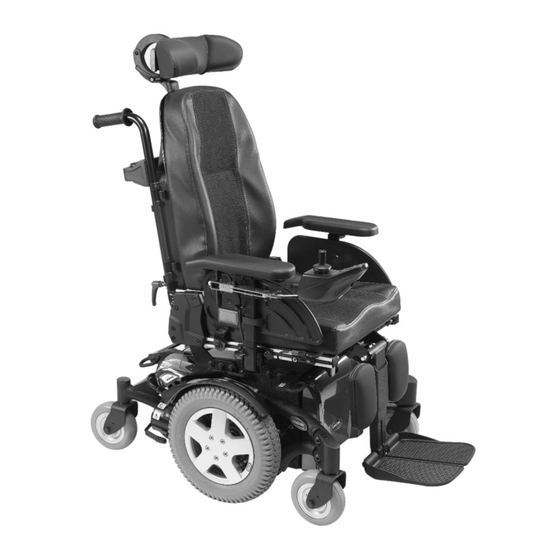
Page 22: Components
3.1 Main parts of the wheelchair Information regarding operation of the lifter at temperatures of less than 0 °C – Invacare mobility aids are fitted with safety mechanisms that prevent capacity overload of the electronic components. At operating temperatures below freezing point this can, in particular, lead to the lifter actuator being shut down after approx. - Page 23 Risk of tipping, if the speed limiter sensors fail when the lifter is raised – If you find that the speed reduction function is not working when the lifter is raised, do not drive with the lifter raised and immediately contact an authorized Invacare dealer. 1578997-C...
-
Page 24: Accessories
Invacare® TDX SP2® Series Harness with metal buckle, adjustable on both sides 4 Accessories 4.1 Postural belts A postural belt is an option which can either be fixed to the mobility device ex-works or can be retrofitted by your specialist dealer. If your mobility device is fitted with a postural belt, your specialist dealer will have informed you about fitting and usage. -
Page 25: Using The Cane Holder
Accessories The buckle should be positioned as centrally as possible. In doing accessories such as the cellphone case supplied by Invacare, which so, carry out adjustments on both sides as much as possible. you can use to transport your cellphone, sports glasses etc. - Page 26 Invacare® TDX SP2® Series instructions which are available from your Invacare dealer or directly from Invacare. More information on the KLICKfix system is available at http://www.klickfix.com. 1578997-C...
-
Page 27: Adjusting The Mobility Device To The User's Seating Posture
If the mobility device does not perform to specifications, IMMEDIATELY turn the mobility device Off and re-enter set-up specifications. Contact Invacare, if mobility device still does not perform to correct specifications. 1578997-C... -
Page 28: Adjustment Possibility For Remote
Invacare® TDX SP2® Series CAUTION! CAUTION! Damage to mobility device and accident hazard Risk of the remote being pushed backwards It is possible that collisions can occur between mobility during an accidental collision with an obstacle, device components due to various combinations of... -
Page 29: Adjusting The Remote For The Length Of The User's Arm
Adjusting the mobility device to the user's seating posture 5.2.1 Adjusting the remote for the length of the 5.2.3 Swivelling the remote to the side user's arm Loosen wing bolt A. Shift the remote forwards or backwards to the desired distance. If your mobility device is fitted with a swing-away remote holder, Retighten the bolt. -
Page 30: Adjusting The Width Of The Armrests
Invacare® TDX SP2® Series Loosen wing screw A. Adjust armrest to desired height. Re-tighten wing screw. 5.3.2 Adjusting the width of the armrests WARNING! Serious injury hazard if one of the armrests falls out of its bracket because they have been... -
Page 31: Adjusting The Height (Flip-Up Armrest)
Adjusting the mobility device to the user's seating posture 5.3.5 Adjusting the height (following armrest) Tools: • 5 mm Allen key • 13 mm open-ended spanner Loosen the screws A and move the armrest lengthwise. Tighten the screws. 5.3.4 Adjusting the height (flip-up armrest) Loosen the screw A and nut B and remove them. -
Page 32: Adjusting The Arm Pad Angle (Flip-Up/Following Armrest)
Invacare® TDX SP2® Series Loosen screws A. Tools: • 5 mm Allen key Do not remove them. Adjust arm pad to desired angle. Tighten screws. 5.3.8 Adjusting the position of the arm pad of the flip-up armrest Tools: • 5 mm Allen key To make the armrest easier to move, release the screw A with the Allen key. -
Page 33: The Hip Support
Adjusting the mobility device to the user's seating posture Removing hip support Pull lever A upwards. Remove hip support from holder. Position the armrest horizontally. Re-tighten the bolts. Inserting hip support Make sure that the Nordlock washers used are re-inserted. Insert hip support in holder. - Page 34 Invacare® TDX SP2® Series Loosen screws A. Adjust hip support to desired width. You can adjust the width only smaller than the seat width but not wider. Tighten screws. Adjusting angle of hip support Tools • 5 mm Allen key Loosen screw A.
- Page 35 Adjusting the mobility device to the user's seating posture Loosen the two screws A. Adjust hip pad to desired depth. Loosen the two screws A. Tighten screws. Adjusting hip pad height You can adjust the hip pad height in two ways: •...
-
Page 36: Adjusting The Seat Width
The description of how the width is adjusted is contained in the service instructions for this mobility device. The service instructions can be ordered from Invacare. However, they contain instructions for specially trained service technicians and describe operations that are not intended for the end user. - Page 37 Adjusting the mobility device to the user's seating posture On both sides, loosen the bottom backrest screw A. Do not remove the screws! Move the backrest to the required seat depth. You can adjust the seat depth steplessly. Use scale B on the seat as a guide for this purpose.
-
Page 38: Adjustment Options For Max Seat
Invacare® TDX SP2® Series 5.4 Adjustment options for Max seat 5.4.1 Changing the armrest position Requirements: • 1 x 6 mm Allen key Unscrew screw A with Allen key. Adjust armrest to required height. Retighten the screw. 5.4.3 Adjusting the width of the armrests Requirements: •... -
Page 39: Adjusting The Seat Depth
Adjusting the mobility device to the user's seating posture Loosen the screws (1). Adjust the armrest to the desired width. Retighten the screw. Repeat this procedure for the second armrest. 5.4.4 Adjusting the seat depth CAUTION! Risk of damage to the power wheelchair if the sideways and central seat depth adjustment is not set identically –... -
Page 40: Adjusting The Seat Angle
Invacare® TDX SP2® Series 5.5 Adjusting the seat angle Loosen all screws on both sides. Set the required angle. CAUTION! Retighten the screws. Adjusting the seat tilt or the backrest angle changes the geometry of the mobility device and 5.6 Adjusting the backrest directly influences its dynamic stability! –... -
Page 41: Adjusting The Width Of The Backrest
For a replacement description, see the service instructions for this mobility device. The service instructions can be ordered from Invacare. However, they contain instructions for specially trained service technicians and describe operations that are not intended for the end user. -
Page 42: Unit)
Invacare® TDX SP2® Series 5.6.3 Adjusting the backrest angle (Modulite seat unit) CAUTION! Every change to the seat angle and the backrest angle alters the geometry of the power wheelchair and affects its dynamic stability – For more information on stability, overcoming... -
Page 43: Adjusting The Backrest Angle (Max Seat)
Adjusting the mobility device to the user's seating posture Remove the saving and the bolt (1). Flip the backrest forward. Loosen the knurled nut (2). On both sides, loosen and remove the middle backrest screw A. With the spindle, adjust the desired angle of the backrest. Set the required backrest angle in 7.5°... -
Page 44: Adjusting The Tension Adjustable Backrest
Invacare® TDX SP2® Series 5.6.5 Adjusting the tension adjustable backrest 5.6.6 Adjusting the backrest bend upholstery Remove the backrest cushion (attached with Velcro strips) by Figure 1 pulling it up and off to access the adjustment straps. The backrest is designed with different angles as shown in figure 1. - Page 45 Adjusting the mobility device to the user's seating posture Loosen the handwheels A and raise the push handles as far as possible. Loosen the screws B and remove the backrest by lifting upwards. Remove the cushion. Turn the backrest 180°. 1578997-C...
- Page 46 Invacare® TDX SP2® Series Put the backrest back by fitting it to the receivers on the tubes. Put the cushion and cover back. Tighten the screws. Lower the push handles and tighten the hand wheels. 1578997-C...
-
Page 47: Adjusting The Headrest
This can cause the neck to be hyperextended during collisions. – A headrest must be installed. The headrest optionally supplied for this mobility device by Invacare is perfectly suitable for use during transport. – The headrest must be adjusted to the user's ear height. -
Page 48: Adjusting The Cheek Supports
Invacare® TDX SP2® Series 5.8 Adjusting the trunk supports 5.8.1 Adjusting the width Loosen knob A. Adjust headrest or neckrest to required height. Loosen the knobs A that hold the lateral supports. Retighten knob. Adjust the supports to the desired width. -
Page 49: Adjusting The Depth
Adjusting the mobility device to the user's seating posture 5.8.3 Adjusting the depth 5.9.1 Laterally adjusting the tray Requirements: • Allen key 5 mm Loosen wing-screw (1). Adjust tray towards the left or right. Re-tighten wing-screw. 5.9.2 Adjusting the depth of the tray / removing the Loosen the screws A that allows the support pads to slide tray forwards and backwards. -
Page 50: Swinging The Tray Away To The Side
Invacare® TDX SP2® Series Loosen wing-screw A. Adjust tray to desired depth (or remove it entirely). Re-tighten screw. 5.9.3 Swinging the tray away to the side The tray can be swivelled up and away to the side to allow the user to get in and out of the mobility device. -
Page 51: Setting The Length Of The Leg Rest
Adjusting the mobility device to the user's seating posture 5.10.4 Setting the angle of the footplate Tools: • 5/32'' (4 mm) Allen key Hold the leg rest securely. Pull the lever (1). Push the leg rest into the required position. Fold the footplates up in order to access the adjusting screws (1). -
Page 52: Vari-F Footrest
Invacare® TDX SP2® Series 5.11 Vari-F footrest Tools: • 6 mm Allen key 5.11.1 Swivelling the footrest/legrest outward and/or removing The small unlocking button is located on the upper section of the footrest/legrest. When the footrest/legrest is unlocked, it can be swivelled inward or outward when getting into the wheelchair as well as being removed completely. -
Page 53: Setting The End Stop Of The Footrest
Adjusting the mobility device to the user's seating posture The end position of the footrest is determined by means of a rubber stop (1). Loosen the screw (1) using the Allen key. Set the desired angle. Re-tighten the screw. 5.11.3 Setting the end stop of the footrest Tools: The rubber stop can be screwed in or out (A) or pushed up •... - Page 54 Invacare® TDX SP2® Series Move the rubber stop to the desired position. Re-tighten the counternut. Use the Allen key to loosen the screw (1) and swivel the footrest upward in order to access the rubber stop. Use the open-ended spanner to loosen the counternut (1).
-
Page 55: Adjusting The Length Of The Legrest
Adjusting the mobility device to the user's seating posture 5.12 Vari-A legrests 5.11.4 Adjusting the length of the legrest 5.12.1 Swivelling the footrest/legrest outward and/or CAUTION! removing Risk of injury due to incorrect adjustment of the footrests and legrests The small unlocking button is located on the upper section of the –... -
Page 56: Setting The End Stop Of The Legrest
Invacare® TDX SP2® Series Set the desired angle. Loosen the locking knob (1) counter-clockwise at least one turn. Turn the knob clockwise to tighten it. 5.12.3 Setting the end stop of the legrest Hit the knob to release the locking mechanism. - Page 57 Adjusting the mobility device to the user's seating posture The end position of the legrest is determined by means of a rubber stop (1). Loosen the locking knob (1) counter-clockwise at least one turn. The rubber stop can be screwed in or out A or pushed up or down B.
- Page 58 Invacare® TDX SP2® Series Move the rubber stop to the desired position. Re-tighten the counternut. Swivel the legrest upward in order to access the rubber stop. Use the open-ended spanner to loosen the counternut (1). Move the legrest to the desired position.
-
Page 59: Adjusting The Length Of The Legrest
Adjusting the mobility device to the user's seating posture 5.12.4 Adjusting the length of the legrest Tools: • 10 mm open-ended spanner CAUTION! Risk of injury due to incorrect adjustment of the footrests and legrests – Before and during every journey it is imperative to ensure that the legrests contact neither the caster wheels nor the ground Tools:... -
Page 60: Unlocking And Swivelling The Calf Pad Backward When Alighting
Invacare® TDX SP2® Series Unlock the legrest and swivel outward. Use the Allen key to loosen the screws (1). The calf pad swivels backward on its own. Adjust to the desired position. Re-tighten the screws. 5.12.7 Unlocking and swivelling the calf pad backward when alighting Lift leg over the heel strap and place on the ground. -
Page 61: Adjusting The Angle- And Depth-Adjustable Foot Plate
Adjusting the mobility device to the user's seating posture 5.13 ADM legrests 5.13.1 Swivelling the footrest/legrest outward and/or removing The small unlocking button is located on the upper section of the footrest/legrest. When the footrest/legrest is unlocked, it can be swivelled inward or outward when getting into the wheelchair as well as being removed completely. -
Page 62: Adjusting The Length Of The Legrest
Invacare® TDX SP2® Series Lowering CAUTION! Risk of injury due to incorrect adjustment of the footrests and legrests – Before and during every journey it is imperative to ensure that the legrests contact neither the caster wheels nor the ground... -
Page 63: Adjusting The Depth Of The Calf Pad
Adjusting the mobility device to the user's seating posture Use the spanner to loosen the screw (1). Adjust to the desired length. Use the open-ended spanner to loosen the nut (1) and remove. Re-tighten the screw. Adjust to the desired depth. Please observe that the round holes are intended for the calf pad retaining screw and the oblong 5.13.4 Adjusting the depth of the calf pad holes for the aglet without thread. -
Page 64: Unlocking And Swivelling The Calf Pad Backward When Alighting
Invacare® TDX SP2® Series Unlock the legrest and swivel outward. Use the Allen key to loosen the screws (1). The calf pad swivels backward on its own. Adjust to the desired position. Re-tighten the screws. 5.13.6 Unlocking and swivelling the calf pad backward when alighting Lift leg over the heel strap and place on the ground. -
Page 65: Adjusting The Angle- And Depth-Adjustable Foot Plate
Adjusting the mobility device to the user's seating posture 5.14 Powered elevating legrests (ADE legrests) 5.14.1 Swivelling the legrest outward and/or removing The small unlocking button is located on the upper section of the legrest. When the legrest is unlocked, it can be swivelled inward or outward when getting into wheelchair as well as being removed completely. -
Page 66: Adjusting The Length Of The Legrest
Invacare® TDX SP2® Series Use the spanner to loosen the screw (1). CAUTION! Adjust to the desired length. Risk of injury due to incorrect adjustment of the Re-tighten the screw. footrests and legrests – Before and during every journey it is imperative to 5.14.4 Adjusting the depth of the calf pad... -
Page 67: Adjusting The Height Of The Calf Pad
Adjusting the mobility device to the user's seating posture 5.14.5 Adjusting the height of the calf pad Tools: • 4 mm Allen key Unlock the legrest and swivel outward. The calf pad swivels backward on its own. Use the Allen key to loosen the screws (1). Adjust to the desired position. -
Page 68: Adjusting The Angle- And Depth-Adjustable Foot Plate
Invacare® TDX SP2® Series 5.15 Legrests for Max seat 5.15.1 Adjusting the height of the calf pad Requirements: • Crosstip screwdriver Use the Allen key to loosen both set screws on the foot plate. Adjust to the desired angle. Re-tighten the screws. -
Page 69: Adjusting The Calf Pad Width
Adjusting the mobility device to the user's seating posture 5.15.3 Adjusting the length of the legrest CAUTION! Risk of injury due to incorrect adjustment of the footrests and legrests – Before and during every journey it is imperative to ensure that the legrests contact neither the caster wheels nor the ground Tools: •... -
Page 70: Adjusting The Width Of Side-Mounted Legrests
Invacare® TDX SP2® Series 5.16 Adjusting the width of side-mounted legrests Tools: • 13 mm open-ended spanner The screws that allow width adjustment of side-mounted legrests are located under the seat (1). Loosen the screws using the open-end spanner. Adjust the legrest to the desired position. -
Page 71: Usage
Usage 6 Usage If installed, make sure to properly adjust and use the postural belt each time you use the mobility device. 6.1 Driving Sitting comfortably = Driving safely CAUTION! Before each trip, make sure that: Risk of unexpected driving behavior due to locked •... -
Page 72: Removing The Standard Armrest In Order To Side Transfer
Invacare® TDX SP2® Series 6.4.1 Removing the standard armrest in order to If you do not have sufficient muscle strength, you should ask side transfer other persons for help. Use a sliding board, if possible. Getting into the mobility device: Position your mobility device as close as possible to your seat. -
Page 73: Maximum Obstacle Height
Usage 6.5.2 Maximum obstacle height CAUTION! Risk of falling out of the mobility device and You can find information about maximum obstacle heights in the damage to the mobility device such as broken chapter entitled 11 Technical data, page 96. casters 6.5.3 Safety information when taking obstacles –... -
Page 74: Driving Up And Down Gradients
For information concerning the maximum safe slope, refer to 11 Technical data, page 96. required by national legislation, then your mobility device needs to be fitted with an appropriate lighting system. Contact your Invacare dealer if you have any questions. 1578997-C... -
Page 75: Pushing The Mobility Device In Freewheel Mode
Usage 6.8 Pushing the mobility device in freewheel mode The motors of the mobility device are equipped with automatic brakes, preventing that the mobility device starts rolling out of control when the remote is switched off. When pushing the mobility device manually whilst freewheeling, the magnetic brakes must be disengaged. -
Page 76: Electrical System
A defective main fuse may be replaced only after checking • Try to provide a 24 hour charge once a week to make sure that the entire electric system. An specialized Invacare dealer both batteries are fully charged. must perform the replacement. You can find information on •... -
Page 77: How To Charge The Batteries
WARNING! be left unattended during charging. All charging devices which Risk of electric shock and damage to the batteries are supplied by Invacare comply with these requirements. – NEVER attempt to recharge the batteries by attaching • You cannot overcharge the batteries when using the charger cables directly to the battery terminals. -
Page 78: Instructions On Using The Batteries
Invacare® TDX SP2® Series • • Always store the batteries fully charged. When only one red LED is flashing, the Battery Safe feature • Do not leave the batteries in a low state of charge for an is enabled. From this time, speed and acceleration is reduced extended length of time. -
Page 79: General Instructions On Handling The Batteries
Dead or damaged batteries can be given back to your dealer or • The batteries reach their end of life when the drive range is directly to Invacare. significantly smaller than usual. Contact your dealer or service 7.2.10 Removing the batteries technician for details. - Page 80 Invacare® TDX SP2® Series Tools: • 11 mm jaw spanner • Slotted screwdriver Remove the side-mounted legrests if fitted. A centrally-fitted, manually adjustable legrest should be put in its top position by turning the spindle A. Remove the thumb screws securing the front shroud/battery retention bracket to the wheelchair A.
- Page 81 Electrical system CAUTION! Risk of crushing The seat can fall down a few centimeters when removing the actuator without securing the seat. – Hold the seat in position while removing the actuator and then lower it carefully. Slide out the battery tray A with the batteries. Disconnect the battery straps B.
- Page 82 Invacare® TDX SP2® Series 10. Installation takes place in reverse order. 11. Check all vehicle functions. 12. Check the new battery status and charge completely. 1578997-C...
-
Page 83: Transport
Transport 8.2 Transferring the mobility device to a vehicle 8 Transport WARNING! 8.1 Transport — General information The mobility device is in danger of tipping over if it is transferred to a vehicle while the driver is CAUTION! still seated in the mobility device Injury hazard or material damage if a mobility –... -
Page 84: Use Of The Mobility Device As A Seat In A Vehicle
Web: www.unwin-safety.com eyes and the identification label sticker: – If compatible, use the Docking Station system (available separately) as an alternative way to safely use this wheelchair as a vehicle seat. Contact Invacare for more details. WARNING! Risk of injury Safety restraint devices must only be used when the wheelchair user's weight is 22 kg or more. - Page 85 (UK for example), but may also CAUTION! be obtained from Invacare as an option in other countries. Risk of injury exists if a mobility device that is not fitted with leak-proof batteries is transported in a This mobility device complies with the requirements of ISO 7176-19 vehicle.
-
Page 86: How The Mobility Device Is Anchored In A Vehicle
This can cause the neck to be hyperextended during collisions. – A headrest must be installed. The headrest optionally supplied for this mobility device by Invacare is perfectly suitable for use during transport. – The headrest must be adjusted to the user's ear height. -
Page 87: Transporting The Mobility Device Without Occupant
CAUTION! Risk of injury – If you are unable to fasten your mobility device securely in a transport vehicle, Invacare recommends The pelvic belt should be positioned in the area between the user's that you do not transport it. pelvis and thighs so that it is unobstructed and not too loose. The ideal angle of the pelvic belt to the horizontal is between 45°... - Page 88 Invacare strongly recommends that you additionally disconnect or remove the batteries. Refer to Removing the batteries. • Invacare strongly recommends securing the mobility device to the floor of the transporting vehicle. 1578997-C...
-
Page 89: Maintenance
Maintenance found in the service manual for this device, which can be obtained 9 Maintenance from Invacare. That manual, however, is intended to be used by trained and authorized service technicians, and describes tasks which 9.1 Maintenance introduction are not intended to be performed by the user. -
Page 90: Weekly
It is confirmed by stamp and signature that all jobs listed in the inspection schedule of the service and repair instructions have been properly performed. The list of the inspection jobs to be performed can be found in the service manual which is available through Invacare. - Page 91 Maintenance Delivery Inspection 1st Annual Inspection Stamp of authorized dealer / Date / Signature Stamp of authorized dealer / Date / Signature 2nd Annual Inspection 3rd Annual Inspection Stamp of authorized dealer / Date / Signature Stamp of authorized dealer / Date / Signature 1578997-C...
-
Page 92: Short-Term Storage
Invacare® TDX SP2® Series 4th Annual Inspection 5th Annual Inspection Stamp of authorized dealer / Date / Signature Stamp of authorized dealer / Date / Signature 9.4 Short-term storage Storing mobility device and batteries In case a serious fault is detected, a number of safety mechanisms are •... -
Page 93: Repair Instructions
11 Technical data, page 96, or consult the service manual, • Repair kit for tire repair or a new inner tube available from Invacare (in this connection please see the addresses • Talcum powder and phone numbers at the end of this user manual). In case you •... - Page 94 Invacare® TDX SP2® Series Removing the wheel Unscrew valve cap. Depressurise tire completely by pressing in the pin in the valve. Block up the vehicle (place wooden blocks under frame). Remove the 5 cylinder head screws (back of the wheel, 2) Unscrew the screw (1).
-
Page 95: After Use
Electric components and printed circuit boards are disposed of as electronic scrap. • Exhausted or damaged batteries can be returned to your medical equipment supplier or Invacare. • Disposal must be carried out in accordance with the respective national legal provisions. -
Page 96: Technical Data
Invacare® TDX SP2® Series 11 Technical data 11.1 Technical specifications The technical information provided hereafter applies to a standard configuration or represents maximum achievable values. These can change if accessories are added. The precise changes to these values are detailed in the sections for the respective accessories. - Page 97 Technical data Drive wheel tires • Tire type 3.00 - 8” puncture-proof, puncture–protected, pneumatic Tire pressure The recommended maximum tire pressure in bar or kpa is marked on the side wall of the tire or the rim. If more than one value is listed, the lower one in the corresponding units applies. (Tolerance = -0.3 bar, 1 bar = 100 kpa) Caster tires •...
- Page 98 Invacare® TDX SP2® Series Driving characteristics • Pivot width 1350 mm • Drive range in accordance with ISO 7176-4 up to 31 km (73.5 Ah batteries) • up to 22 km (60 Ah batteries) • up to 20 km (50 Ah batteries)
- Page 99 Technical data Seat type Dimensions according to ISO 7176–15 Modulite • • Seat height (without seat 450 mm 470 mm • • angle adjustment or lifter) 475 mm 495 mm • • Seat height (with seat angle 450 mm (manual and 20° electrical adjustment) 470 mm •...
- Page 100 Invacare® TDX SP2® Series Seat type Dimensions according to ISO 7176–15 Modulite • Armrest height Telescopic seat frame: 250-340 mm • 290-380 mm • 245 - 310 mm (T-armrest) • 230 – 360 mm (flip-up armrest) • 230 – 300 / 300 – 360 mm (following armrest) Single-part seat frame: •...
- Page 101 Technical data Footrests and legrests • ADM (manual) Length 290 - 460 mm • Angle 80° – 0° • Center-mounted (manual) Length 280 – 385 mm • Angle 90° – 0° Weight TDX SP2 NB TDX SP2 • • Curb weight with fixed seat angle approx.
- Page 102 Horizontal distance of wheel axle from intersection of loaded seat and backrest reference planes The actual curb weight depends on the fittings your mobility device has been supplied with. Every Invacare mobility device is weighed when leaving the works. Refer to the nameplate for the curb weight (including batteries) measured.
- Page 103 Notes...
- Page 104 Invacare Sales Companies Australia: Ireland: New Zealand: Canada: Invacare Australia PTY. Ltd. Invacare Canada LP Invacare Ireland Ltd, Invacare New Zealand Ltd 1 Lenton Place, North Rocks NSW 570 Matheson Blvd E. Unit 8 Unit 5 Seatown Business Campus 4 Westfield Place, Mt Wellington 1060...