Invacare TDX SP2 Series Service Manual
Hide thumbs
Also See for TDX SP2 Series:
- User manual (128 pages) ,
- Service manual (56 pages) ,
- User manual (88 pages)

Related Manuals for Invacare TDX SP2 Series


Summary of Contents for Invacare TDX SP2 Series
- Page 1 Invacare® TDX® SP2 Series en Power Wheelchair Service Manual DEALER: Keep this manual. The procedures in this manual MUST be performed by a qualified technician.
- Page 2 All rights reserved. Republication, duplication or modification i n w hole o r i n p art i s p rohibited w ithout p rior written permission from Invacare. Trademarks are identified b y ™ a nd ® . A ll t rademarks a re o wned b y o r l icensed t o Invacare Corporation or its subsidiaries unless otherwise noted.
-
Page 3: Table Of Contents
Contents 7.7.2 Replacing motor/gearbox assembly....36 7.7.3 Replacing or rotating motor/gearbox assembly sealing ring....... . 38 1 General . -
Page 4: General
• For LiNX® controls, refer to LiNX Service Manual. • Refer to the Invacare website located on the back IMPORTANT page of manuals for the most recent manual revisions. – Indicates a hazardous situation that could... -
Page 5: Safety
• Always wear eye protection when working on any approved Invacare accessories. Unapproved defective or possibly defective batteries. accessories have not been tested by Invacare for use with Invacare products. Safety gloves – DO NOT use unapproved accessories. It is possible that battery acid can be discharged when –... - Page 6 Off immediately and reenter cleaning agents. set up specifications. Contact Invacare, if – DO NOT expose battery charger or other wheelchair still does not perform to correct accessories to sources of liquid or dampness.
- Page 7 Safety WARNING! WARNING! Risk of Injury, Damage or Death Risk of Injury or Damage Improper routing of cable(s) may cause tripping, Unintended movement may cause injury or entanglement or strangulation hazard that may damage. result in injury, damage or death. –...
- Page 8 Traveling down inclines in reverse could cause dealers. the wheelchair to tip over resulting in death – Invacare supplies all mobility devices with a or serious injury standard drive program ex-works. Invacare – DO NOT travel down inclines in reverse.
-
Page 9: Electrical
– Be aware that a pinch point C may occur batteries are “hazardous material” and MUST be recycled when rotating the center mount front rigging through an approved agency. Contact your provider or assembly. Invacare on proper disposal and recycling of your batteries. 1195667-E... -
Page 10: Electromagnetic Compatibility (Emc) Information
– Report all incidents of unintended movement Some cellular telephones and similar devices or brake release to Invacare and note whether transmit signals while they are ON, even when there is a source of EMI nearby. not being used. -
Page 11: Powered Wheelchair Electromagnetic Emissions
To avoid impacting the operation and function of other products: – Products not specified by Invacare that may be used on or near the mobility device may be impacted by emissions from this product if... -
Page 12: Component Overview
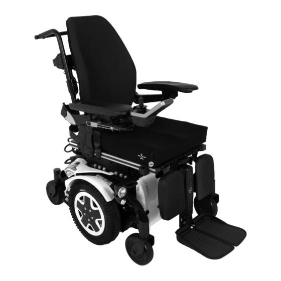
Invacare® TDX® SP2 Series 3.4 Component Overview ITEM DESCRIPTION Back Cushion Armrest Remote (Joystick) Seat Cushion Drive Wheel Fork Caster Front Rigging Back Cane Headrest Fig. 3-1 1195667-E... -
Page 13: Hygiene
Regular cleaning will reveal loose or worn parts and enhance the smooth operation of your wheelchair. To operate properly and safely, your wheelchair must be cared for just like any other vehicle. For upholstery that is severely stained or surface finish that is badly damaged, contact Invacare for further information. -
Page 14: Wiring Guide
Invacare® TDX® SP2 Series 5.2 Common Causes of Wiring Damage 5 Wiring Guide Improperly routed wiring may become damaged under the The following are guidelines ONLY. Location of following conditions: electronic components and wiring may vary from power wheelchair to power wheelchair according •... -
Page 15: Wiring Guidelines For Component Replacement
The following are recommended guidelines for the routing Ensure wiring connections are secure. and securing of wiring while removing/installing or Inspect electrical components for signs of replacing electronic components or wiring on Invacare corrosion. Replace if corroded or damaged. power wheelchairs. Verify charger function. -
Page 16: Bundling The Wiring
Invacare® TDX® SP2 Series 5.5 Bundling the Wiring 5.6 Recommended Wire Routing and Securement Points DANGER! Risk of Death or Serious Injury The following figures contain examples of common wire Electric shock can cause death or serious injury. routing and securement points. However, it must be noted –... -
Page 17: Checking Cable Connections
Wiring Guide Power Module Wiring The lower bundle of cables is tie wrapped to the The front and rear lighting cables are bundled with rear pivot and includes the cables referenced in the motor cable at the rear of the base. the table and the lighting cables. -
Page 18: Testing
Disconnect motor plug (3) from power module. 6. If there is a defect, replace motor and send it to Invacare Service for inspection or repair. Ensure that the multimeter is set to Ohms. A resistance of between 40 and 80 ohms indicates an intact brake. -
Page 19: Rain Test
Testing WARNING! batteries are tested under load using a digital voltmeter Risk of injury or damage to check battery charge level at the charger connector. The charger connector is located on the remote. When Unintended or erratic operation during testing voltage at the output drops more than 2.0 volts under may result in injury or damage. -
Page 20: Service
Invacare® TDX® SP2 Series 7 Service IMPERIAL METRIC inch 7.1 Imperial to metric conversion chart 16.2719 41/64 16.6688 21/32 You can use this chart as an orientation to find the right 17.0656 43/64 tool size. 17.4625 11/16 IMPERIAL METRIC 17.8594... -
Page 21: Labels On The Product
Service 1167422 3/8”-16 25–41 Nm (18.44–30.24 ft-lb) 40–67 Nm (29.50–49.42 7/16”-14 ft-lb) 60–100 Nm (44.25–73.76 1/2”-13 Fig. 7-3 *Controller Label ft-lb) 1035900 9/16”-12 90–150 Nm (66.38–110.63 ft-lb) Fig. 7-4 Transportation Label 5/8”-11 130–210 Nm (95.88–154.89 1111028 ft-lb) 230–370 Nm 3/4”-1 (169.64–272.90 ft-lb) Fig. - Page 22 Invacare® TDX® SP2 Series 1114847 1114848 Fig. 7-10 **22NF Battery Wiring Diagram Label Fig. 7-12 **GP24 Battery Wiring Diagram Label 1114825 1118356 Fig. 7-13 *** 22NF Battery Label 1118355 Fig. 7-14 *** GP24 Battery Label 1098362 Fig. 7-15 Positive Battery Wire...
-
Page 23: Batteries
Service On ALL Positioning Belts 1195057 Fig. 7-18 Patent Label 1195679 Fig. 7-19 Driving Surfaces Label * Label located under the controller. ITEM PART DESCRIPTION NUMBER ** Labels located under front shroud. Only one set of labels will appear depending on chair model. 1195716 *** Only one of the battery labels (22NF or GP24) will appear depending on chair model. -
Page 24: General Instructions On Charging
Use only charging devices in Class 2. This class of twice the volume of the wheelchair. chargers may be left unattended during charging. All charging devices which are supplied by Invacare WARNING! comply with these requirements. Risk of short circuit and electric shock if the •... -
Page 25: How To Disconnect The Mobility Device After
After Charging manual are based on the use of deep cycle gel cell batteries. Invacare strongly recommends their use 1. Once charging is complete, disconnect the battery as the power source for this unit. -
Page 26: Instructions On Using The Batteries
Invacare® TDX® SP2 Series DO NOT USE THIS TYPE • Driving with flashing red LED’s means an extreme PROPER BATTERIES TO USE OF BATTERY stress for the battery and should be avoided under normal circumstances. • When only one red LED is flashing, the Battery Safe feature is enabled. -
Page 27: How To Handle Damaged Batteries Correctly
• Only ever transport damaged batteries in an Invacare strongly recommends battery installation appropriate acid-resistant receptacle. and replacement be performed by a qualified • Wash all objects that have come into contact with technician. -
Page 28: Removing The Batteries From The Wheelchair
Invacare® TDX® SP2 Series 7.4.12 Removing the Batteries from the 6. Remove the hardware securing the battery tray to the Wheelchair frame: • Wheelchairs Manufactured Before 11/01/2018 CAUTION! and ALL Wheelchairs with 5° or 10° Fixed Anterior Risk of Damage... -
Page 29: Installing Batteries Into The Wheelchair
Service 7.4.13 Installing Batteries into the Wheelchair 1. Position the battery with the dual connector bracket (one side of the connector for the controller and the WARNING! other side is for the remaining battery) M against the Risk of Serious Injury back edge of the battery tray I in the orientation Improperly installed battery tray can cause as shown. - Page 30 Invacare® TDX® SP2 Series 6. Secure the battery tray to the wheelchair frame H: 8. Install the rear shroud, front shroud and battery • Wheelchairs Manufactured Before 11/01/2018, retention bracket. Refer to 7.9 Removing/Installing ALL Wheelchairs with 5° or 10° Fixed Anterior the Shrouds, page 43.
-
Page 31: Replacing Batteries And/Or Battery Cables
Service 7.4.14 Replacing Batteries and/or Battery WARNING! Cables Risk of Death or Serious Injury Failure to observe these warnings can cause an electrical short resulting in death, serious injury, or damage to the electrical system. Have the following tools available: –... -
Page 32: Cleaning Battery Terminals
Invacare® TDX® SP2 Series 7.5 Stability lock 7.4.15 Cleaning Battery Terminals WARNING! 7.5.1 Checking Stability Lock Function Risk of Injury Exposure to battery acid may result in injury. – The use of rubber gloves is recommended when working with batteries. -
Page 33: Checking Actuator Function
Service 6. If the clearance has changed, repeat STEPS 3 and 4 to reset the clearance to 0.040 in (1.02 mm). 7. Check that stability lock is functioning properly. a. Refer to 7.5.1 Checking Stability Lock Function, page 32. b. If the stability lock functions improperly, check the gas cylinder actuator. - Page 34 Invacare® TDX® SP2 Series WARNING! 6. Remove the screw F securing the bezel bracket G to Risk of Injury or Damage the battery box H. Unintended movement may cause injury or damage. – Turn power off BEFORE adjustment or service.
-
Page 35: Walking Beams
Service 7.6 Walking Beams 18. If replacing the walking beam, perform the following steps. Otherwise, proceed to STEP 19. a. Remove the motor/gearbox assembly from the 7.6.1 Removing the Walking Beam existing walking beam. Refer to 7.7.2 Replacing motor/gearbox assembly, page 36. b. -
Page 36: Replacing The Lower Pivot Link
B. These parts may be replaced as an assembly 7.6.4 Replacing rubber stopper or separately. 7.7.2 Replacing motor/gearbox assembly Invacare recommends that you replace all rubber stoppers as soon as one needs replacing. WARNING! Risk of Injury or Damage... - Page 37 Service Installing motor/gearbox assembly 1. Replace defective components: • Motor/Gearbox Assembly: Proceed to STEP 2. • Motor or Gearbox: a. Use a wrench to loosen and remove the nut and washer (2). b. Remove the screw (1) which secures the sealing ring (3).
-
Page 38: Sealing Ring
Invacare® TDX® SP2 Series 5. Reverse the steps in Removing motor/gear box 3. Remove the screw (1) which secures the sealing ring assembly, page 37 to install the motor/gearbox (3). assembly. 4. Carefully bend the sealing ring apart and remove it. -
Page 39: Replacing Brake Lever Cap (Before 09/01/2020)
Service 10.4.1 Replacing brake lever and cap (after 3. Remove distance ring (5). 4. Remove wheel hub (4) from axle (2). 09/01/2020) 5. Remove shim rings (3). 6. Remove feather key (1) from axle. Removing brake lever and cap (after 09/01/2020) Installing drive wheel hub 1. -
Page 40: Wheels
Service 7.8 Wheels 7.8.1 Replacing rim inserts in drive wheels Removing rim insert 1. Insert tip of screwdriver between rim and rim insert. 2. Remove rim insert. Installing rim insert 1. Hold insert over rim. Place two 5-inch blocks under battery box to Carefully push to fasten rim insert, until foot of rim lift frame off the ground for ease in performing insert A snaps and rim insert B clings to rim. -
Page 41: Replacing Tire Or Inner Tube
Invacare® TDX® SP2 Series 7.8.3 Replacing tire or inner tube Replacing flat free gel foam tires There are two different types of tires or inner tubes, and specific points must be observed for the replacement of each type. The individual types of tires can be easily distinguished: •... -
Page 42: Replacing Caster Fork
Service 1. Loosen and remove screw (2). 2. Take cap (1) off head tube (3). Fig. 7-66 Removing head tube Front caster shown. Front and rear casters 1. Remove the screws A and washers B securing the install in the same way. head tube C to the walking beam D. -
Page 43: Adjusting Caster Fork
Invacare® TDX® SP2 Series 6. Adjust caster as described in adjusting caster fork. 8. Repeat adjustment steps if necessary until casters are adjusted correctly. 9. Replace cap (1) and tighten screw (2) hand tight. 7.8.7 Replacing casters on double-sided caster forks Fig. -
Page 44: Replacing Wheel Lock Assembly
Service 7.9 Removing/Installing the Shrouds Removing caster 1. Remove the mounting screw (3) and washer (1) from CAUTION! the single-sided fork (2). – Place the wheelchair in a well ventilated area 2. Remove existing caster (4) from single-sided fork. where work can be performed without risking 3. - Page 45 Invacare® TDX® SP2 Series Removing 1. Remove the front riggings. Fig. 7-78 Removing Front Shroud/Battery Retention Bracket — All models for Australia and New Zealand and North American models BEFORE 11/01/18 without 5° or 10° fixed anterior assist Fig. 7-80 •...
-
Page 46: Replacing Top Shroud
Service 7.9.3 Replacing top shroud Install isolation shroud. 1. Secure isolation shroud B to frame with hardware A. 2. Ensure isolation shroud is secure. 3. Install front shroud. Refer to 7.9.2 Removing/Installing the Front Shroud, page 43. 7.9.5 Replacing bezel shroud Removing top shroud 1. -
Page 47: Replacing Rear Cap
Invacare® TDX® SP2 Series 6. Secure with new cable ties. 7. Ensure bezel shroud is secure. 8. Test function of lights. If lights do not function properly, check connections and refer to troubleshooting. 9. Install the rear shroud. Refer to 7.9.1 Removing/Installing the Rear Shroud, page 7.9.6 Replacing rear cap... -
Page 48: Replacing G-Trac Sensor
Service 7.11 Lighting unit 3. Cut tie-wraps (not shown) and disconnect cables from power module. 7.11.1 Replacing headlight complete (LED lighting system) Removing headlight 1. Remove rear shroud. 2. Carefully note location of cable routing and the connection locations of the various plugs. Either mark each plug, socket and cable routing or take a photograph with a digital camera. -
Page 49: Replacing Complete Rear Light
Invacare® TDX® SP2 Series Removing lamp holder Open connector plug (3) for the rear light which needs 1. Remove complete headlight. to be replaced. 2. Loosen and remove two retaining screws (2) with 4. The rear lights are only clamped in by the plastic washers. -
Page 50: Troubleshooting
1. First assess the possible cause of the problem using from the original manufacturer's manuals. You can the following table. obtain the original manuals from Invacare®. 2. Check the remote status display. Evaluate the flash error code. 3. Carry out the necessary checks and repairs as recommended in the following table. - Page 51 Invacare® TDX® SP2 Series Problem Other symptoms Possible cause Solution Documentation None Motors stop and start Voltage decline Stop driving and allow again electronics to cool down None Motor runs but loses High motor load Stop driving and allow power...
-
Page 52: Charger Fault Diagnosis
Check mains supply cable. Replace damaged cables or send charger to Invacare® Service for repair LEDs are burnt out Send charger to Invacare® Service for repair An internal fuse might be burnt out Send charger to Invacare® Service for repair... -
Page 53: Service Plan (1X Annually)
Invacare® TDX® SP2 Series Symptom Possible cause Solution Battery charger could be defective Use battery charger which you know is working properly to charge batteries. Send defective battery charger to Invacare® Service for repair. Battery voltage is too low to operate Replace batteries. - Page 54 Troubleshooting Component Notes Check Remedy Motors Drive units, clutch Check motors mechanism Check functions in Replace motor if drive and push modes necessary Check clutch Tighten screws/nuts, mechanism adjust or replace if necessary Brakes Inspect motor brake Test motor brake Legrests Check welded seams, Tighten, replace if...
- Page 55 Notes...
- Page 56 Invacare Corporation Canada New Zealand Manufacturer: 570 Matheson Blvd E Unit 8 Invacare New Zealand Ltd Invacare Corporation Mississauga Ontario, L4Z 4G4 4 Westfield Place, Mt Wellington 1060 1200 Taylor Street Canada New Zealand Elyria, Ohio USA Tel: 800–668–5324 Tel: 0800 468 222 44035 www.invacare.ca...