Table of Contents
Advertisement
Quick Links
WARNING:
If the information in these instructions is not followed exactly, a fire or
explosion may result causing property damage, personal injury or loss of
life.
-
Do not store or use gasoline or other flammable vapors and liquids in the vicinity of this
or any other appliance.
WHAT TO DO IF YOU SMELL GAS
• Do not try to light any appliance.
• Do not touch any electrical switch; do not use any phone in your building.
• Immediately call gas supplier from a neighbor's phone. Follow the gas supplier's
instructions.
• If you cannot reach your gas supplier, call the fire department.
-
Installation and service must be performed by a qualified installer, service agency or the
gas supplier.
This appliance may be installed in an aftermarket permanently
located, manufactured home (USA only) or mobile home, where
not prohibited by local codes.
This appliance is only for use with the type(s) of gas indicated on
the rating plate. A conversion kit is supplied with the appliance.
Installation Manual
Installer:
After installation give this manual to the home-
owner and explain operation of this heater.
© Copyright 2009, T.I.
$10.00
100-01217_000
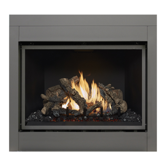
864 See Through
GreenSmart™
Fireplace
Tested and Listed by
OMNI-Test Laboratories, Inc.
Portland, Oregon
Report # 028-F-84-5
ANSI Z21.88b-2003
•
Built-In Direct Vent Fireplace
•
Natural Gas or Propane
•
Residential or Mobile Home
www.travisproducts.com
4800 Harbour Pointe Blvd. SW
4090507
Mukilteo, WA 98275
Advertisement
Table of Contents

Related Manuals for Travis Industries GREEN SMART 864


Summary of Contents for Travis Industries GREEN SMART 864
- Page 1 WARNING: If the information in these instructions is not followed exactly, a fire or explosion may result causing property damage, personal injury or loss of life. Do not store or use gasoline or other flammable vapors and liquids in the vicinity of this or any other appliance.
-
Page 2: Introduction Overview
Overview This manual details the installation requirements for the 864 See Through (ST) GS fireplace. For operating and maintenance instructions, refer to the 864 ST GS Owner's Manual (part # 100- 01218). Listing Details This appliance was listed by OMNI Test Labs to ANSI Z21.88 - report # 028-F-84-5. -
Page 3: Table Of Contents
Introduction Overview ... 2 Listing Details ... 2 Safety Precautions Safety Precautions ... 4 Features and Specifications Features ... 6 Installation Options ... 6 Heating Specifications ... 6 Dimensions ... 6 Installation Packing List ... 7 Additional Items Required ... 7 Recommended Installation Procedure ... -
Page 4: Safety Precautions
Safety Warnings: • Failure to follow all of the requirements may result in property damage, bodily injury, or even death. • This unit must be installed by a qualified installer to prevent the possibility of an explosion. • This appliance must be installed in accordance with all local codes, if any; if not, in U.S.A. follow ANSI Z223.1 and NFPA 54(88). - Page 5 Safety Warnings (continued): • Allow the heater to cool before carrying out any maintenance or cleaning. • Operate the heater according to the instructions included in this manual. • If the main burners do not start correctly turn the gas off and call your dealer for service. •...
-
Page 6: Features And Specifications
Installation Options • Residential or Mobile Home • Flush or Recessed Face • Raised or Floor Placement Heating Specifications Approximate Heating Capacity (in square feet)* Maximum BTU Input Per Hour Heating capacity will vary with floor plan, insulation, and outside temperature. Dimensions Top Vent Configuration 8"... -
Page 7: Installation
Installation Packing List • Propane Conversion Kit • Log Set • Firestop (sku 93006094) • Right Side Standoffs (2) Additional Items Required • Direct Vent • Gas Line Equipment (shutoff valve, pipe, etc.) • Electrical Equipment (min. 14 gauge, grounded line) •... -
Page 8: Massachusetts Requirements
Installation Massachusetts Requirements NOTE: The following requirements reference various Massachusetts and national codes not contained in this document. Requirements for the Commonwealth of Massachusetts For all side wall horizontally vented gas fueled equipment installed in every dwelling, building or structure used in whole or in part for residential purposes, including those owned or operated by the Commonwealth and where the side wall exhaust vent termination is less than seven (7) feet above finished grade in the area of the venting, including but not limited to decks and porches, the following requirements shall be satisfied:... -
Page 9: Converting The Fireplace To Side Vent Configuration
Installation Top Vent or Side Vent Configuration This appliance is shipped in the top vent configuration. To change to the side vent configuration, follow the directions below. NOTE: the vent configuration affects several aspects of installation (framing, maximum vent rise, maximum vent run). - Page 10 Installation Converting the Fireplace to Side Vent (continued) Re-attach the flue assembly in the side position. Tuck the two 20" (508mm) pieces of insulation into the area above the exhaust manifold and fireplace can. Note how the insulation is folded in half and covers the entire area above the exhaust manifold (see illustration below).
-
Page 11: Fireplace Placement Requirements
Installation Fireplace Placement Requirements • Fireplace must be installed on a level surface capable of supporting the fireplace and vent. • Fireplace must be placed directly on wood or non-combustible surface (not on linoleum or carpet). • This heater may be placed in a bedroom. Please be aware of the large amount of heat this appliance produces when determining a location. -
Page 12: Min. Framing Dims. - Rear Vent Configuration
Installation Minimum Framing Dimensions – Top or Side Vent Configuration Minimum 42”(1067mm) Fireplace Enclosure Height NOTE: The shaded framing must be installed after placing the fireplace in position. The framing above the fireplace interferes with the top of the fireplace. If using the side vent configuration, do not install the framing to the left side (shown in light gray). -
Page 13: Nailing Brackets
Installation Nailing Brackets There are eight nailing brackets on the front and back of the fireplace. Bend the tabs out to position the nailing brackets. Once in place, nail or screw the nailing brackets to the framing. NOTE: Additional nailing brackets are provided along the base of the fireplace. -
Page 14: Gas Line Requirements
Installation Gas Line Requirements MASSACHUSETTS INSTALLATIONS - WARNING: THIS PRODUCT MUST BE INSTALLED BY A LICENSED PLUMBER OR GAS FITTER WHEN INSTALLED WITHIN THE COMMONWEALTH OF MASSACHUSETTS. OTHER MASSACHUSETTS CODE REQUIREMENTS: • Flexible connector must not be longer than 36 inches. •... - Page 15 Installation Gas Line Location Right Side Gas Inlet (preferred) A 8" (203mm) flex tube and shutoff valve is included with the fireplace. The shutoff valve accepts a 1/2"MPT. Left Side Gas Inlet An additional 2" (51mm) by 3" (76mm) opening is located the left side. It is centered 3"...
-
Page 16: Electrical Connection (Required)
Installation Electrical Connection (required) • The electrical line to the grounded receptacle inside the fireplace must be installed by a qualified installer and must meet all local codes. • Make sure the household breaker is shut off prior to working on any electrical lines. •... -
Page 17: Optional Wall Switch Or Thermostat Installation
Installation Optional Wall Switch or Thermostat Installation Do not connect 110-120 VAC to the gas control valve or wiring system of this fireplace. The switch and wiring must be installed by a qualified installer. This fireplace includes an optional wall switch (with wire) to operate the fireplace burner without accessing the internal on/off switch. -
Page 18: Vent Requirements
Installation Vent Requirements • The gas appliance and vent system must be vented directly to the outside of the building, and never be attached to a chimney serving a separate solid fuel or gas-burning appliance. Each direct vent gas appliance must use its own separate vent system. -
Page 19: Approved Vent
Installation Approved Vent • Side vent configurations use 8" (203mm) diameter Simpson Dura-Vent Model Direct-Vent Pro (or GS)*. • Top vent configurations use 8" (203mm) or 6-5/8" (168mm) diameter Simpson Dura-Vent Direct-Vent Pro (or GS)*. If using 6-5/8" (168mm) diameter vent, attach the 8" (203mm) to 6-5/8" (168mm) reducer (Travis part # 98900165) to the fireplace. -
Page 20: Approved Vent Configurations
Installation Approved Vent Configurations Restrictor Position • Intake and exhaust restrictors are built into the appliance to adjust the flow rate of intake air and exhaust gases. Depending upon the vent configuration, you may be required to adjust the restrictor positions. The charts for acceptable vent configurations detail the correct vent restrictor positions. -
Page 21: Intake Restrictor Adjustment
Installation Intake Restrictor Adjustment The intake restrictor is shipped in position # 1 (open). To adjust the restrictor to position # 2 (closed), follow the directions below. © Travis Industries (for qualified installers only) Restrictor Plate Rotate the restrictor plate so the left side hole lines up with the screw-hole. -
Page 22: Diffuser Plate Adjustment
Installation Diffuser Plate Adjustment Certain vent configurations require the diffuser plate to be adjusted (refer to the approved vent configuration charts for details). See the directions below to change the diffuser to position. DIFFUSER SIDE VIEW Before (Stock - Position # 2) After (Position # 1) ©... -
Page 23: Rear Vent Config. W Horizontal Term. (No Vertical Rise)
Installation Side Vent Configuration with Horizontal Termination (no vertical rise) • The termination must fall within the shaded area shown in the chart. Use the indicated restrictor and diffuser positions. HINT: Travis Industries provides a minmum vent kit (sku 98900168). It includes a 4” (102mm) section and a horizontal termination cap. -
Page 24: Rear Vent Config. W Horizontal Term. (W Vertical Rise)
Installation Side Vent Configuration with Horizontal Termination (with vertical rise) • The termination must fall within the shaded area shown in the chart. Use the indicated restrictor and diffuser positions. • Up to four elbows (45° or 90°) may be used. •... -
Page 25: Side Vent Configuration With Vertical Termination
Installation Side Vent Configuration with Vertical Termination • The termination must fall within the shaded area shown in the chart. Use the indicated restrictor and diffuser positions. • Up to four elbows (45° or 90°) may be used. • Only one horizontal elbow may be used. -
Page 26: Top Vent Configuration With Horizontal Termination
Installation Top Vent Configuration with Horizontal Termination • The termination must fall within the shaded area shown in the chart. Use the indicated restrictor and diffuser positions. • Up to four elbows (45° or 90°) may be used. • May use 8" (203mm) or 6-5/8" (168mm) diameter vent (see page for 18 details). •... -
Page 27: Top Vent Configuration With Vertical Termination
Installation Top Vent Configuration with Vertical Termination • The termination must fall within the shaded area shown in the chart. Use the indicated restrictor and diffuser positions. • Up to four elbows (45° or 90°) may be used. • Only one horizontal 35 feet (10.5m) elbow may be used. -
Page 28: Termination Requirements
Installation Termination Requirements Venting terminals shall not be recessed into a wall or siding. Minimum 9" (229mm) clearance from any door or window Minimum 12" (305mm) above any grade, veranda, porch, deck or balcony Minimum 3-3/8" (86mm) from outside corner walls NOTE: Clearance in accordance with local installation codes and the requirements of the gas supplier. -
Page 29: Hearth Requirements
Installation Hearth Requirements Floor Mounted Fireplaces Raised Fireplaces Fireplace Stand © Travis Industries (for qualified installers only) Do not build a hearth more than 1”(25mm) above the baseplate (this area must remain clear for the access door). If installed near carpet or other combustible flooring, the fireplace must be raised so the base of the unit is above the carpet surface or... -
Page 30: Facing Requirements
Installation Facing Requirements • This appliance is designed to allow for drywall (or other combustible facing) to contact the sides and top of the front of the fireplace. • Tile or other non-combustible facing may be placed on the front of the fireplace (see "Facing Overview" on page 31 for further details). -
Page 31: Facing Overview
Installation Facing Overview Upgrade faces are available for this fireplace and may influence facing installation. Consult with your Travis Dealer if you are using an upgrade face. Optional non-combustible facing may be installed on the fireplace. Use the guidelines below to determine the location (also see the following pages for detailed diagrams. -
Page 32: Thin Facing Installation
Installation Thin Facing Installation (tile, marble, or other non-combustible under 1" (25mm) thick) Upgrade faces are available for this fireplace and may influence facing installation. Consult with your Travis Dealer if you are using an upgrade face. Facing is installed to this edge of the fireplace. - Page 33 Installation Thin Facing Installation (tile, marble, under 1" (25mm) thick) - Side View Raised Fireplace (with no Hearth) Floor-Mounted Fireplace (with Hearth) © Travis Industries (for qualified installers only) Drywall Tile or other facing under 1'' (25mm) thick. Face SIDE OF FIREPLACE Note how the facing extends 1'' (25mm) above the base of the fireplace.
-
Page 34: Thick Facing Installation
Installation Thick Facing Installation (stone, brick, or other non-combustible over 1" (25mm) thick) If using a Fireplace Xtrordinair (FPX) arched face, see "Thick Facing with a Fireplace Xtrordinair Arched Faces" on page 35. Do not install masonry (or other material) in front of the fireplace. -
Page 35: Thick Facing Installation With Fpx Arched Faces
Installation Thick Facing with Fireplace Xtrordinair (FPX) Arched Faces The following illustration shows facing considerations for those fireplaces utilizing FPX arched faces. The facing must be non-combustible and over 1" (25mm) in depth. The Fireplace Xtrordinair 864 Masonry Template is recommended for masonry installation (sku 98500688). - Page 36 Installation Thick Facing Installation - Side View Floor-Mounted Fireplace (with Hearth) Raised Fireplace (with no Hearth) © Travis Industries (for qualified installers only) Drywall Masonry or other non-combustible over 1'' (25mm) thick SIDE OF FIREPLACE Face Hearth (note how it extends under the face - max. 1'' (25mm) thick).
-
Page 37: Mantel Requirements
Installation Mantel Requirements Combustible Mantels • Use the table below to determine the maximum mantel depth allowed. The mantel depth (measured from the face of the fireplace) must fall in the shaded portion of the table. • Any material that protrudes more than 3/4” (19mm) from the non-combustible facing is considered a mantel and must meet the mantel requirements. -
Page 38: Finalizing The Installation
Finalizing the Installation Steps for Finalizing the Installation Remove the glass (see page 40). NOTE: If using propane (LP) convert the appliance prior to installing the logs. We recommend you purge the gas line at this time (with the glass removed). This allows gas to be detected once it enters the firebox, ensuring gas does not build up. -
Page 39: Air Shutter Adjustment
Finalizing the Installation Install the logs (see page 42). Replace the glass. Start the heater. Leak test all gas joints. Check the air shutter following the directions below. Air Shutter Adjustment Let the heater burn for fifteen minutes (make sure the logs and glass are in place). The flames should be yellow with no sooting. -
Page 40: Glass Frame Removal And Installation
Finalizing the Installation Glass Frame Removal and Installation The appliance must be completely cool before removing the glass. Warning: Do not strike or slam the glass. Warning: Based upon the face being used, either: (a) swing the access door down and remove the top grill, (b) remove the face (unscrew or lift off - see the instructions included with the face for details). - Page 41 Finalizing the Installation Glass Frame Removal and Installation (continued) The latch can come loose from glass frame anchor. This occurs when it is turned 1/4 turn when it is disengaged. Follow the directions below to re-install the latch if it becomes loose. Hold the latch at an angle and insert it into the slot on the glass frame anchor.
-
Page 42: Log Set Installation
Finalizing the Installation Log Set Installation Logs in Place – FRONT SIDE (gas control valve side) NOTE: This fireplace has a front side and back side. The front side (pictured belowj) is the side with the gas control valve. Logs in Place – BACK SIDE ©... - Page 43 Finalizing the Installation Center Log Installation The log shelf has two tabs used to align the center log. Bend these tabs as shown to the right. Place the center log in place. Make sure the two tabs on the log shelf insert into the two holes on the bottom of the log.
- Page 44 Finalizing the Installation Front Left Log Place the front left log as shown below. There is a ledge on the bottom of the log that aligns with the edge of the center burner. When in place, the front left log has a small gap to the center log. ©...
- Page 45 Finalizing the Installation (for qualified installers only) Front Left Upper Log There are two pins on the front left log. The pin to the right is used to locate the front left upper log. The front left upper log has a groove and one hole on the bottom.
- Page 46 Finalizing the Installation Front Upper Center Log The front upper center log has two holes on its bottom surface. One of the holes fits over the pin on the center log (see picture to the right). The other fits over the pin on the front left log.
- Page 47 Finalizing the Installation (for qualified installers only) Back Left Log The back left log fits to the left of the center log. The groove on the bottom of the log fits over the upper burner tray. Make sure to slide the log towards the center of the firebox.
- Page 48 Finalizing the Installation Right Ember Chunk The right ember chunk is installed from the back. The groove on the bottom of the ember fits over the edge of the upper burner tray. It wedges between the two logs.. When in place, the left ember chunk looks like the picture to the right.
- Page 49 Finalizing the Installation (for qualified installers only) Back Left Log The pin on the center log inserts into the hole on the back of the back left log. This groove on the log fits over the grate. When in place, the log looks like the picture to the right.
- Page 50 Finalizing the Installation Back Upper Right Log Pins on the center log and back right log help locate this log. When in place, the back upper right log looks like the picture to the right. © Travis Industries (for qualified installers only) 4090507 100-01217_000...
- Page 51 Finalizing the Installation Ember Placement A bag of embers is provided to further enhance the firebox. Place the embers on the firebox floor and on the outer burner (especially over exposed rivets on the burner). Do not place embers over any of the burner holes or air channels.
-
Page 52: Lp Conversion Instructions
Finalizing the Installation LP Conversion Instructions Install the conversion kit prior to installing the gas line to ensure proper gas use. Remove the glass (see page 38). Remove the logs and embers (if installed - page 42). Remove the grate , firebacks, and center burner (see illustration below). 1/4"... - Page 53 Finalizing the Installation Follow the directions below to remove the outer burner and replace the orifices. Remove the outer burner. Center Burner Orifice Outer Burner Orifice Use a 1/2” open end wrench to unscrew the two orifices. Manifold Screw each LP orifice in so the orifice protrudes 15/16”...
- Page 54 Finalizing the Installation Remove the pilot orifice following the instructions below. Replace with the propane pilot orifice Lift the pilot hood off the pilot assembly. Replace the firebox components. Install the logs and embers. Replace the glass. Remove and discard the screws (see “a” below) holding the stock regulator in place (see “b” below). Remove the stock regulator and gasket (see “c”...
-
Page 55: Optional Equipment
Optional Equipment Fireback Installation Turn off gas to the appliance and make sure it has fully cooled prior to conducting WARNING: service. Remove the glass frame and logs. Remove the front and rear grates (NOTE: lift the burner slightly to remove the grate - see the illustration below). - Page 56 Optional Equipment Carefully place the floor firebacks into position. You must tip them under and around the corners of the burner. Once in place, bend the accent light deflectors back to the correct position (take care to not damage the halogen bulbs).
-
Page 57: Grill Installation
Optional Equipment Grill Installation Certain faces allow for installation of an upper and lower grill. Follow the directions below to install. Hold the grill at an angle and insert the lower slot over the bushing on the fireplace (both Upper Grill sides). -
Page 58: Extra Room Power Heat Duct
Optional Equipment Extra Room Power Heat Duct SKU 98500769 Special Instructions for 864 ST The 864 ST has a removable cover plate shield below the heat duct connections. This allows more heat to be routed to the power heat ducts (see below for details). Otherwise the heat duct is installed the same as an 864TRV (one heat duct kit maximum, manually-controlled on/off operation –... -
Page 59: Andiron Installation
Optional Equipment Andiron Installation Install the andirons after installing all other optional equipment (firebacks, accent light, etc) but before installing the logs. Part Numbers: Arabesque 98500633 -- Colonial 98500631 -- Wrought Iron 98500632 Disassemble one of the andiron brackets. © Travis Industries (for qualified installers only) 5/32”... -
Page 60: Installation Packing List
Optional Equipment GreenSmart™ Remote Control Installation Packing List • Transmitter • Receiver (with Cover Plate & Switch) • Fan Control Module • Velcro • LP or NG Stepper Motor (with screws and label - attaches to Valve) • Wire Harness •... - Page 61 Optional Equipment Overview The GreenSmart remote installs onto a 864 fireplace and replaces the stock wiring harness. Before installing, familiarize yourself with the stock and updated wiring diagrams (see the illustrations on this page and and following page). Stock Wiring Diagram Accent Light (s) Accent Light...
-
Page 62: Greensmart Wiring Diagram
Optional Equipment GreenSmart Wiring Diagram Comfort Control Valve Ground Orange Yellow / Green Blue White CONTINUOUS PILOT INTERMITTENT PILOT Thermodisk Optional Blower(s) © Travis Industries (for qualified installers only) Spark Rod Pilot Sensor Pilot Green IPI / CPI FAN CONTROL Fan Controller POWER 110V OUT... - Page 63 Optional Equipment Installation Make sure power to the fireplace has been shut off prior to installation. WARNING: Refer to the wiring diagram on page 62 while making wiring harness connections. NOTE: Remove the concealment cover from the front of the fireplace (see Figure 1). Unscrew the four screws holding the control cover in place (see Figure 2).
- Page 64 Optional Equipment Disconnect the molex connector leading to the gas control valve (see Figure 5). WARNING: The tabs on the gas control valve are fragile. Take care when removing the molex connector to not pull or damage the wires or tabs. Disconnect the two leads on the back of the control panel for the IPI / CPI switch (continuous pilot / greensmart pilot –...
- Page 65 Optional Equipment Unscrew the on/off/battery plate from the control panel (see Figure 9). Pull the plate and wiring forward (see Figure 10). The control panel has plastic wire-locks attached to the back (see Figure 11). Un-hook the wires from the wire-locks and remove the wiring harness, plate, battery holder, and ac adapter (see Figure 12).
- Page 66 Optional Equipment The stepper motor (adjustable regulator) has an installation sheet included with it – make sure to follow all of the directions. Place the stepper motor on the gas control valve (see Figure 14) – MAKE SURE IT IS CORRECTLY ORIENTED. Secure using the screws included with the motor (see Figure 15) –...
- Page 67 Optional Equipment Attach the blue and white wires to the IPI/CPI switch (see Figure 19). Connect the wiring harness to the stepper motor (see Figure 20). Attach the wiring harness to the comfort control valve connection (see Figure 21). Place the fan controller near the front of the fireplace to the left and connect it to the wiring harness (see Figure 22).
- Page 68 Optional Equipment Disconnect the power lead from accent light and connect it to the power lead included with this kit (see Figure 24). Attach the power lead to the fan controller in the “AUX OUT” receptacle (see Figure 25). NOTE: If using the optional fan, you will want to disconnect its power lead and connect it to the extra power lead included with this kit, then connect it to the “FAN”...
- Page 69 Optional Equipment Pull the “RECEIVER” connector through the control panel and attach to the receiver (see Figure 27). Then attach the receiver to the control panel with the two #8 machine screws (see Figure 28). Place batteries into the receiver and transmitter (see Figure 29). Calibrate the receiver to the transmitter (see Figure 30 - use a paperclip to press the “PRG”...
- Page 70 Optional Equipment Clip any excess wiring into the wire clips on the back of the control panel (see Figure 33). Use the included wire ties, if necessary, to keep all wiring from contacting any hot or moving components. Re-attach the control panel (see Figure 34) and shroud (see Figure 1). A wall mount is included with this kit for the remote.
- Page 71 Optional Equipment (for qualified installers only) © Travis Industries 4090507 100-01217_000...
-
Page 72: Index Index
Index Additional Items Required ... 7 Andiron Installation ... 59 Air Shutter Adjustment ... 39 Altitude Considerations ... 18 Approved Vent Configurations ... 20 Approved Vent ... 19 Battery Installation ... 38 Clearances ... 11 Converting the Fireplace to Side Vent Configuration ... 9 Diffuser Plate Adjustment ...