Table of Contents
Advertisement
Quick Links
WARNING:
If the information in these instructions is not followed exactly, a fire or explosion
may result causing property damage, personal injury or loss of life.
DO NOT PLACE ARTICLES ON OR AGAINST THIS APPLIANCE.
DO NOT USE OR STORE FLAMMABLE MATERIALS NEAR THIS APPLIANCE.
DO NOT SPRAY AEROSOLS IN THE VICINITY OF THIS APPLIANCE WHILE IT IS IN OPERATION.
DO NOT MODIFY THIS APPLIANCE.
Do not store or use gasoline or other flammable vapors and liquids in the vicinity of this or any
other appliance.
WHAT TO DO IF YOU SMELL GAS
• Do not try to light any appliance.
• Do not touch any electrical switch; do not use any phone in your building.
• Immediately call gas supplier from a neighbor's phone. Follow the gas supplier's instructions.
• If you cannot reach your gas supplier, call the fire department.
-
Installation and service must be performed by a qualified installer, service agency or the gas
supplier.
This appliance may be installed in an aftermarket permanently located, manufactured home (USA only) or
mobile home, where not prohibited by local codes.
This appliance is only for use with the type(s) of gas indicated on the rating plate. A conversion kit is
supplied with the appliance.
Installation Manual
Installer:
After installation give this manual to the home-
owner and explain operation of this heater.
Copyright 2014, T.I.
$10.00
100-01412
864 ST GSR2
Fireplace
with Screen (AU)
Listed by
AS 4553-2008
GMK10027
IAPMO-R&T OCEANA
Built-In Direct Vent Fireplace
Natural Gas or Propane
Residential or Mobile Home
Dragon Wholesaling Pty. Ltd.
Unit 4, 16 Lexington Drive
Bella Vista NSW
4141013
Australia 2153
Advertisement
Table of Contents

Related Manuals for Travis Industries 864 ST GSR2


Summary of Contents for Travis Industries 864 ST GSR2
- Page 1 864 ST GSR2 Fireplace with Screen (AU) Listed by AS 4553-2008 GMK10027 IAPMO-R&T OCEANA Built-In Direct Vent Fireplace Natural Gas or Propane Residential or Mobile Home WARNING: If the information in these instructions is not followed exactly, a fire or explosion may result causing property damage, personal injury or loss of life.
-
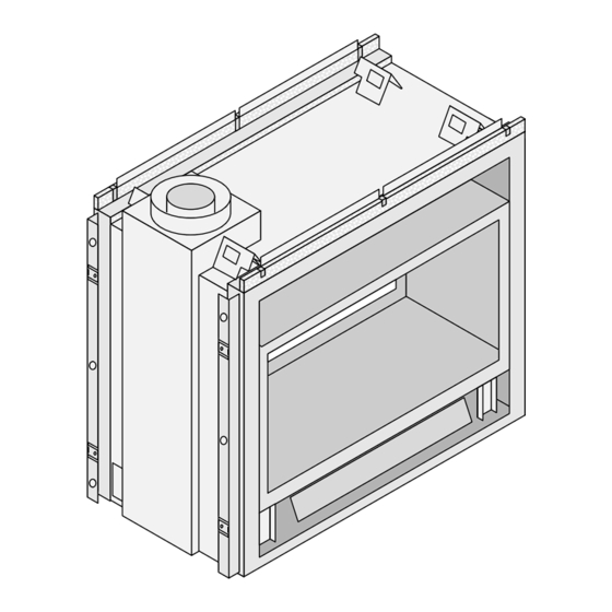
Page 2: Overview
Introduction Overview This manual details the installation requirements for the 864 See Through (ST) GSR2 fireplace. For operating and maintenance instructions, refer to the 864 ST GSR2 Owner's Manual (part # 100-01413). © Travis Industries 4140729 100-01404... -
Page 3: Table Of Contents
Grill Installation ........... 57 Side Vent Configuration with Vertical Andiron Installation ..........58 Termination ............24 GS2 Remote Wiring Diagram ......59 Top Vent Configuration with Horizontal Index ..............60 Termination ............25 © Travis Industries 4140729 100-01404... - Page 4 Because this heater can be controlled by a thermostat there is a possibility of the heater turning on and igniting any items placed on or near the appliance. Light the heater using the built-in igniter. Do not use matches or any other external device to light your heater. © Travis Industries 4140729 100-01404...
- Page 5 Travis Industries, Inc. grants no warranty, implied or stated, for the installation or maintenance of your heater, and assumes no responsibility of any consequential damage(s).
-
Page 6: Installation Options
33-7/8" 860mm Lifting Handle Tabs These tabs may be used in conjuction with the lifting handles (98500711) - make sure to use the required 27" adapters (250-01038) 686mm 1" 25mm Weight: 310 Lbs (140.7 kg) © Travis Industries 4140729 100-01404... -
Page 7: Packing List
In this type of installation, the center of the glass will not be located in the center of the framed opening. The center of the glass will be ¾” (19mm) from the center of the framing. © Travis Industries 4140729... -
Page 8: Massachusetts Requirements
See Gas Connection section for additional Commonwealth of Massachusetts requirements. © Travis Industries 4140729 100-01404... -
Page 9: Top Vent Or Side Vent Configuration
Remove the flue assembly. Tuck the two 24" (610mm) pieces of insulation into the area between the exhaust manifold and fireplace can. WARNING: Failure to properly place the insulation will void the warranty and create a safety hazard. © Travis Industries 4140729 100-01404... -
Page 10: Converting The Fireplace To Side Vent (Continued)10
Re-attach the back plate to the top of the fireplace. NOTE: Make sure the flange on the back plate tucks between the fireplace and the flue assembly. © Travis Industries 4140729 100-01404... -
Page 11: Fireplace Placement Requirements
140.7 Kg) and vent. The base of the fireplace must be a minimum 70” (1778mm) below the room ceiling. Min. 42" (1067mm) Fireplace Enclosure Height Platform Optional Raised Hearth (see "Hearth Requirements" for details) © Travis Industries 4140729 100-01404... -
Page 12: Minimum Framing Dimensions - Top Or Side Vent Configuration
667mm * The 26-1/4" (667mm) dimension is based upon 10mm (3/8") drywall around the perimeter of the fireplace on both sides. If using thicker drywall (or other facing), you will need to adjust this dimension. © Travis Industries 4140729 100-01404... -
Page 13: Nailing Brackets
1/2" or 5/8". NOTE: You may need to bend the tabs out on one side then slide the fireplace out to bend the tabs out on the opposite side TOP VIEW Framing Nailing Bracket Fireplace Drywall © Travis Industries 4140729 100-01404... -
Page 14: Gas Line Requirements
The supply regulator (the regulator that attaches directly to the residence inlet or to the propane tank) should supply gas at the suggested input pressure listed above. Contact the local gas supplier if the regulator is at an improper pressure. © Travis Industries 4140729... -
Page 15: Gas Line Location
4. Attach the shutoff valve plate to the left side of the fireplace. Route the gas line to the left side and re-attach the gas line to the shutoff valve. Make sure to leak test the entire gas line. © Travis Industries 4140729... -
Page 16: Electrical Connection (Required)
National Electrical Code, ANSI/NFPA 70, or the Canadian Electrical Code, CSA C22.1. The electrical line must supply 240 Volts at 60 Hz (2 Amps). Caution: Label all wires prior to disconnection when servicing controls. Wiring errors can cause improper and dangerous operation. © Travis Industries 4140729 100-01404... -
Page 17: Vent Requirements
Failure to adjust the air shutter properly may lead to improper combustion which can create a safety hazard. Consult your dealer or installer if you suspect an improperly adjusted air shutter. © Travis Industries 4140729 100-01404... -
Page 18: Approved Vent
If it does not, apply high temperature sealant to the joints of the affected sections. Horizontal sections require a 1/4" (6mm) rise every 12" (305mm) of travel Horizontal sections require non-combustible support every three feet (e.g.: plumbing tape) © Travis Industries 4140729 100-01404... -
Page 19: Approved Vent Configurations
The screw location indicates restrictor position. In this example, the restrictor is set in position # 3. Tighten the screws to secure the restrictor. (closed) #6 (open - stock position) # 1 Left (vent) Side of Firebox © Travis Industries 4140729 100-01404... -
Page 20: Intake Restrictor Adjustment
The intake restrictor is shipped in position # 1 (open). To adjust the restrictor to position # 2 (closed), follow the directions below. Restrictor Plate Remove this screw. Rotate the restrictor plate so the left side hole lines up with the screw-hole. Re-attach the screw to lock the restrictor plate in position # 2. © Travis Industries 4140729 100-01404... -
Page 21: Diffuser Plate Adjustment
Bend the round portion of the diffuser 90° (position # 1). After (Position # 1) Secure the diffuser plate with the screws removed earlier. Replace the exhaust restrictor (see “Exhaust Restrictor Adjustment” for restrictor settings). © Travis Industries 4140729 100-01404... -
Page 22: Side Vent Configuration With Horizontal Termination (No Vertical Rise)
The termination must fall within the shaded area shown in the chart. Use the indicated restrictor and diffuser positions. HINT: Travis Industries provides a minimum vent kit (sku 98900168). It includes a 4” (102mm) section and a horizontal termination cap. -
Page 23: Side Vent Configuration With Horizontal Termination (With Vertical Rise)
(it does not matter both lengths of horizontal run whether it turns right or left). (Horizontal Length = H1 + H2). It may be a 90° or 45° elbow. This is considered a vertical elbow © Travis Industries 4140729 100-01404... -
Page 24: Side Vent Configuration With Vertical Termination
(it does not matter both lengths of horizontal run whether it turns right or left). (Horizontal Length = H1 + H2). It may be a 90° or 45° elbow. This is considered a vertical elbow © Travis Industries 4140729 100-01404... -
Page 25: Top Vent Configuration With Horizontal Termination
(it does not matter both lengths of horizontal run whether it turns right or left). (Horizontal Length = H1 + H2). It may be a 90° or 45° elbow. This is considered a vertical elbow © Travis Industries 4140729 100-01404... -
Page 26: Top Vent Configuration With Vertical Termination
(it does not matter both lengths of horizontal run whether it turns right or left). (Horizontal Length = H1 + H2). It may be a 90° or 45° elbow. This is considered a vertical elbow © Travis Industries 4140729 100-01404... -
Page 27: Termination Requirements
NOTE: Measure clearances to the nearest edge of the exhaust hood. • Use the vinyl siding standoff when installing on an exterior with vinyl siding. • Vent termination must not be located where it will become plugged by snow or other material © Travis Industries 4140729 100-01404... -
Page 28: Hearth Requirements
Raised A hearth is not required Fireplaces when the fireplace is raised above the flooring surface. Fireplace Stand © Travis Industries 4140729 100-01404... -
Page 29: Facing Requirements
If the fireplace is raised, drywall up to the bottom edge as well. Do not install drywall (or any other combustible) in front of the fireplace. TOP VIEW Framing Nailing Bracket Fireplace Drywall © Travis Industries 4140729 100-01404... -
Page 30: Facing Overview
Optional facing will butte to edge of faceplate (tile (867mm) (937mm) line) Wilmington Hearthview 35-3/4” 41” May fit over top of tile facing (908mm) (1041mm) Winthrop Bungalow 34” 36-7/8” Optional facing will butte to edge of faceplate (tile (864mm) (937mm) line) © Travis Industries 4140729 100-01404... -
Page 31: Thin Facing Installation (Tile, Marble, Or Other Non-Combustible Under 1" (25Mm) Thick)
870mm Upgrade Kit (sku 98500686) and a triangular piece of facing in these upper corners. See the instructions included with the face for further details. 7-7/8" (200mm) 1" (25mm) 2-7/8" 37" 2" (51mm) (73mm) 940mm © Travis Industries 4140729 100-01404... -
Page 32: Thin Facing Installation (Tile, Marble, Under 1" (25Mm) Thick) - Side View
Tile or other facing under 1'' (25mm) thick. Face SIDE OF FIREPLACE Hearth: note how it extends under the face - max. 1'' (25mm) thick. The fireplace may be raised to accommodate thicker hearth materials. Max. 1'' (25mm) Floor © Travis Industries 4140729 100-01404... -
Page 33: Thick Facing Installation (Stone, Brick, Or Other Non-Combustible Over 1" (25Mm) Thick)
(or cement board, etc.) Masonry 1" NOTE: The nailing brackets are not used for this type of installation - secure the fireplace to the floor with 41" the brackets along the base of the fireplace. 1041mm © Travis Industries 4140729 100-01404... -
Page 34: Thick Facing With Fireplace Xtrordinair (Fpx) Arched Faces
Masonry is installed 1" (25mm) maximum (98500686). This covers the upper corners. above the base of the fireplace. FRONT VIEW 5" 127mm TOP VIEW Framing 35-3/4" 45-1/2" (1156mm) Radius 908mm Nailing Bracket Fireplace Drywall Face Masonry 1" 41" 1041mm © Travis Industries 4140729 100-01404... -
Page 35: Thick Facing Installation - Side View
Raised Fireplace (with no Hearth) Masonry or other non-combustible over 1'' (25mm) thick. SIDE OF FIREPLACE Face (Behind Masonry) The masonry extends 1'' (25mm) above the base of the fireplace. 1'' (25mm) Fireplace Support Floor © Travis Industries 4140729 100-01404... -
Page 36: Mantel Requirements
A non-combustible header must be used SIDE OF FIREPLACE Non-Combustible Mantel (metal stud). Non-Combustible Facing © Travis Industries 4140729 100-01404... -
Page 37: Steps For Finalizing The Installation
Install the four AA batteries (see illustration below). The AA batteries act as a power backup in case the household (AC) power goes out and are required for operation. Install three AAA batteries into the remote (see illustration below). Synchronize the transmitter to the IFC (see the Owners Manual). © Travis Industries 4140729 100-01404... -
Page 38: Air Shutter Adjustment
(this is used primarily with brick faces). Acid wash (muriatic acid) is used to remove excess mortar. If not properly neutralized with an ammonia solution, the plated face may develop a permanent tarnish when the acid evaporates over time. Contact your dealer if uncertain your facing has been properly neutralized. © Travis Industries 4140729 100-01404... -
Page 39: Barrier Removal
HINT FOR REPLACING THE BARRIER: Hold the barrier at an angle and insert the bottom slots first. Then pivot the barrier forward to engage the top hooks. © Travis Industries 4140729 100-01404... -
Page 40: Glass Frame Removal And Installation
Lift the glass frame slightly and attach the lower latches. NOTE: Make sure the glass frame is all the way in place - it should be flush with the front of the fireplace when installed. © Travis Industries 4140729 100-01404... -
Page 41: Glass Frame Removal And Installation (Continued)
Top of Firebox Glass Frame Anchor Note how the washer on the latch fits behind the flange on the glass frame anchor. Once fully inserted, turn the latch until it is upright. © Travis Industries 4140729 100-01404... -
Page 42: Log Set Installation
Logs in Place – FRONT SIDE (gas control valve side) NOTE: This fireplace has a front side and back side. The front side (pictured below) is the side with the gas control valve. Logs in Place – BACK SIDE © Travis Industries 4140729 100-01404... -
Page 43: Center Log Installation
Front Left Log Place the front left log as shown below. There is a ledge on the bottom of the log that aligns with the edge of the center burner. © Travis Industries 4140729 100-01404... - Page 44 Finalizing the Installation (for qualified installers only) When in place, the front left log has a small gap to the center log. © Travis Industries 4140729 100-01404...
-
Page 45: Front Left Upper Log
The front left upper log has a groove and one hole on the bottom. The groove fits over the edge of the burner. When in place, the front left upper log looks like the picture to the right. © Travis Industries 4140729 100-01404... -
Page 46: Front Upper Center Log
(see picture to the right). The other fits over the pin on the front left log. When in place, the front upper center log looks like the picture to the right. © Travis Industries 4140729 100-01404... -
Page 47: Back Left Log
The groove on the bottom of the log fits over the upper burner tray. Make sure to slide the log towards the center of the firebox. When in place, the log will appear as shown in the picture to the right. © Travis Industries 4140729 100-01404... -
Page 48: Right Ember Chunk
Back Ember Chunk The back ember in placed on the back right side as shown in the picture to the right. Make sure it is not over any burner holes. © Travis Industries 4140729 100-01404... -
Page 49: Back Left Log
The pin on the center log inserts into the hole on the back of the back left log. This groove on the log fits over the grate. When in place, the log looks like the picture to the right. © Travis Industries 4140729 100-01404... -
Page 50: Back Upper Right Log
(for qualified installers only) Back Upper Right Log Pins on the center log and back right log help locate this log. When in place, the back upper right log looks like the picture to the right. © Travis Industries 4140729 100-01404... -
Page 51: Ember Placement
Use a stiff brush to apply a thin layer of rockwool fibers onto the burner. Do not use the entire bag of rockwool. Use only a small amount and save the remainder. Over-use of rockwool will diminish the glow and may cause sooting or other adverse conditions. © Travis Industries 4140729 100-01404... -
Page 52: Lp Conversion Instructions
Remove the grate from both sides. NOTE: lift the burner to remove the grate. Remove the log shelf Four screws hold the center burner in place. Slide the burner to the right and up to remove. © Travis Industries 4140729 100-01404... - Page 53 Center Burner Orifice the correct orifices. Outer Burner Orifice Look here for the orifice 15/16” Screw each LP orifice in 23.8mm identification so the orifice protrudes 15/16” (23.8mm) indicating full insertion. Center Outer © Travis Industries 4140729 100-01404...
- Page 54 25 Lb-inches. Leak test this area after installation to verify proper installation. Make the gas line connection, bleed the gas line (if applicable), start the heater and thoroughly leak-test all gas connections and the gas control valve. © Travis Industries 4140729 100-01404...
-
Page 55: Fireback Installation
NOTE: If the accent light deflectors have been bent, carefully bend the accent light deflectors inwards on both sides (NOTE: do not over-bend these deflectors, they will break off if over-bent). Remove and discard the steel ember trays. © Travis Industries 4140729 100-01404... - Page 56 Place the side firebacks into position. Secure the clips to anchor the side firebacks. The ceramic firebacks are fragile. Ensure proper alignment of individual pieces in each step. To achieve the ideal appearance, you may need to make slight adjustments. © Travis Industries 4140729 100-01404...
-
Page 57: Grill Installation
You will need to lift the grill slightly to get it over the get the tab over the bushing (this prevents it allows the grill to swing bushing. Once in place the grill is held in place by the grill from accidentally falling off). forward. gravity. © Travis Industries 4140729 100-01404... -
Page 58: Andiron Installation
“a”. You may need to bend the bracket slightly to allow the andirons to stand vertically. Repeat steps “a” through “e” for the opposite side. © Travis Industries 4140729 100-01404... -
Page 59: Gs2 Remote Wiring Diagram
3 Amp Fuse 3 Amp Fuse Appliance Ground 3.15A FUSE Integrated Pilot Sensor Fireplace Flame Control Detect (IFC) Spark System Jumper Appliance Ground IPI/CPI JUMPER WIRE Comfort Control Valve Black (4) AA Batteries Battery Box (Manual On/Off) © Travis Industries 4140729 100-01404... -
Page 60: Index
Top Vent Configuration with Vertical Termination Log Set Installation ........... 42 ..............26 LP Conversion Instructions ......52 Top Vent or Side Vent Configuration ....9 Mantel Requirements ........36 Vent Requirements .......... 17 Massachusetts Requirements ......8 © Travis Industries 4140729 100-01404...