Table of Contents
Advertisement
Quick Links
Advertisement
Table of Contents

Related Manuals for E-FLITE CESSNA 182 370


Summary of Contents for E-FLITE CESSNA 182 370
- Page 1 Cessna 182 370 ARF Cessna, 182 Skylane, (associated emblems and logos, and body designs of vehicles) are either registered trademarks or trademarks of Textron Innovations, Inc. in the USA and/or other countries, used under license by Horizon Hobby. Assembly Manual...
-
Page 2: Table Of Contents
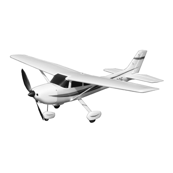
Table of Contents Introduction Introduction ..............2 Thank you for purchasing the Cessna 182 370 ARF Specifications .............2 (EFL2200), a vacuum-formed model of the full-scale Cessna Contents of Kit/Parts Layout .........3 182 Skylane. The Cessna features a vacuum-formed fuselage Required Radio Equipment ...........4 and wing, scale details, and quick final assembly time,... -
Page 3: Contents Of Kit/Parts Layout
Cowl EFLA203 Micro Control Connectors EFL2205 Landing Gear w/Wheel Pants EFLA204 Micro Rubber Spinner EFL2206 Wing Struts EFLA213 E-flite/JR/Horizon Decals EFL2207 Landing Gear Covers EFLM202 Pinion Gear, 12T 0.4 Module EFL2208 Fuselage Tail Fairing EFLM216 Gearbox, 5.33:1 (v2) EFLM217 Spur Gear, 64T w/Shaft... -
Page 4: Required Radio Equipment
Required Radio Equipment Important Information About Motor Selection You will need a 4-channel transmitter, crystals, micro receiver, and four sub-micro servos. You can choose to We are recommending the E-flite™ Park 370 Brushless purchase a complete radio system that includes all of these Motor with 4100Kv (EFLM1000) or the Park 400 Outrunner items or if you are using an existing transmitter, just purchase Brushless Motor, 920Kv. -
Page 5: Sport Setup (Stock Gearbox)
High Power Setup (stock gearbox)* Sport Setup (stock gearbox) EFLM1000 Park 370 Inrunner Brushless Motor, EFLM1000 Park 370 Inrunner Brushless Motor, 4100 Kv 4100 Kv EFLA311B 20-Amp Brushless ESC (V2) EFLA311B 20-Amp Brushless ESC (V2) EFLP1070 10 x 7 Slow Flyer Prop (2) - keep extras EFLP1070 10 x 7 Slow Flyer Prop (2) - keep on hand... -
Page 6: Sport Outrunner Setup
Sport Outrunner Setup High Power Outrunner Setup* EFLM1305 Park 400 Outrunner Motor, 920 Kv EFLM1305 Park 400 Outrunner Motor, 920 Kv EFLA311B 20-Amp Brushless ESC (V2) EFLA311B 20-Amp Brushless ESC (V2) EFLM1915 Outrunner Stick Mount EFLM1915 Outrunner Stick Mount EFLP1070 10 x 7 Slow Flyer Prop (2) EFLP1070 10 x 7 Slow Flyer Prop (2) -
Page 7: Required Tools And Adhesives
Required Tools and Adhesives Tools & Equipment Adhesives EFLA250 Park Flyer Tool Assortment, 5pc EFLA208 Thick Foam CA/Activator Pack Or Purchase Separately Or Purchase Separately EFLA257 Screwdriver, #0 Phillips (or included with EFLA206 Foam Compatible Thick CA (included EFLA250) with EFLA208) EFLA255 Nut Driver, 5.5mm (or included with EFLA207... -
Page 8: Using The Manual
Using the Manual Before Starting Assembly This manual is divided into sections to help make assembly Before beginning the assembly of your Cessna 182, remove easier to understand, and to provide breaks between each each part from its bag for inspection. Closely inspect the major section. -
Page 9: Warranty Information
Warranty Information Horizon Hobby, Inc. guarantees this kit to be free from Once assembly of the model has been started, you must defects in both material and workmanship at the date of contact Horizon Hobby, Inc. directly regarding any warranty purchase. -
Page 10: Landing Gear Installation
Landing Gear Installation 2. Use the 10mm x 136mm tape to attach the landing gear fairings to the landing gear. Required Parts Fuselage Landing gear Landing gear fairing (2) 10mm x 136mm tape (2) 1. Locate the landing gear. Press the gear into the slot in the bottom of the fuselage. -
Page 11: Inrunner Motor Installation
When Airframe 5.33:1 (64T spur) gearbox installing your motor into the E-flite™ gearbox, Brushless motor Brushless speed control it is very important that the gear mesh is set 2mm x 8mm screw (2) correctly and is smooth with no binding. - Page 12 2. Attach the motor to the gearbox using the screws 3. Slide the gearbox onto the motor stick. Use a provided with the motor. hobby knife to drill a hole through the plastic and into the motor stick. Secure the gearbox using a 2mm x 8mm wood screw on the top and one or even two in the side.
- Page 13 It may be necessary to use a servo extension. Exact speed control location may vary depending on the brand used and the center of gravity. This photo shows the location in the front of the fuse if you are using our E-flite™ 20-amp Brushless ESC.
-
Page 14: Outrunner Motor Installation
Airframe Brushless motor Brushless speed control 2. When using the E-Flite™ outrunner motor and Outrunner Mount (EFLM1915 - sold separately) mount, you will need to shorten the motor mount 2mm x 8mm wood screw (2) stick by 13/16" (20mm). Use a razor saw to cut Required Tools and Adhesives the motor mount stick. - Page 15 This photo shows the location in the front of the fuse if you are using our E-flite™ 20-amp Brushless ESC. Hint: You may want to plug in the speed control...
-
Page 16: Cowling Installation
Cowling Installation Note: If you have selected the outrunner motor option, install the propeller adapter onto the Required Parts motor shaft. Airframe Rubber spinner or propeller adapter 3mm locknut 3mm washer 10 x 7 propeller 2mm x 5mm screw (4) Required Tools and Adhesives Phillips screwdriver (small) Hobby knife... - Page 17 2. Secure the cowling using four 2mm x 5mm 3. Press the spinner into position (if using the screws. Secure the propeller using the Inrunner and gearbox option). 3mm washer and 3mm locknut. Note: Simply tighten the adapter when using the outrunner and associated propeller mounting hardware.
-
Page 18: Radio Installation
Radio Installation 1. Attach a micro control connector to the servo arm for the elevator. Use the connector backplate to Required Parts secure the connector. Fuselage Wing Micro control connector (5) Control connector backplate (5) 2mm x 8mm screw (8) Aileron servo cover (2) 3"... - Page 19 3. Repeat Steps 1 and 2 for the rudder servo, but 5. Pass the pushrods for the rudder and nose install two connectors instead of one. wheel through the connectors. With the radio on, physically center the rudder and nose wheel. Tighten the screw in the connector to secure the pushrod wires.
- Page 20 7. Attach a micro control connector to the servo arm 6. Attach the receiver to the side of the fuselage for the aileron. Use the connector backplate to using a piece of hook and loop. Plug the servo secure the connector.
- Page 21 8. Center the aileron servo using the radio by 9. Route one end of the female side of the 6" attaching the male side of the Y-harness to the Y-harness to the aileron servo location using receiver and attaching the servo arm to the servo.
- Page 22 10. Secure the cover to the wing using four 11. Attach the “Z” bend of the 3" control 2mm x 8mm screws. linkage to the control horn. Slide the wire through the connector on the servo arm. Center the servo using the radio, and physically center the aileron.
-
Page 23: Wing And Stabilizer Installation
Wing and Stabilizer Installation 1. Plug the aileron extension into the receiver. Slide the wing into position and secure it using the Required Parts 3mm x 12mm socket head bolt and 3mm Wing Fuselage plastic washer. Be careful not to over-tighten Stabilizer 3mm x 12mm socket head bolt the wing bolt. - Page 24 2. Snap the wing struts into position on the 3. Slide the stabilizer into position. Use a ruler to wing and fuselage. Slide the fairing in the check that the distance between the stabilizer tips strut into place. and wing tips are the same.
- Page 25 5. Once the stabilizer has been aligned, use 7. Slide the elevator pushrod wire through the foam-compatible CA to glue the stabilizer to the micro control connector. Attach the "Z" bend fuselage. to the elevator control horn. With the radio on and elevator trim centered, physically center the elevator.
-
Page 26: Battery Installation
Battery Installation 2. Install the battery door to the bottom of the fuselage. The magnet will hold the battery hatch Required Parts in place. Assembled airframe Battery Battery door Required Tools and Adhesives Foam-compatible CA 1. With the aircraft fully assembled, install the battery into the battery compartment. -
Page 27: Control Throws
Control Throws Ailerons: 1. Turn on the transmitter and receiver of your 1/4" (6mm) Up/Down Cessna 182. Check the movement of the rudder using the transmitter. When the stick is moved Elevator: 5/8" (16mm) Up/Down right, the rudder should also move right. Reverse the direction of the servo at the transmitter if Rudder: necessary. -
Page 28: Center Of Gravity
Center of Gravity Range Testing the Radio Caution: Do not inadvertently skip this step! 1. Before each flying session, be sure to range The recommended Center of Gravity (CG) location for the check your radio. This is accomplished by "... -
Page 29: Preflight
Preflight Note: Keep loose items that can get entangled in the propeller away from the prop. These Check Your Radio include loose clothing, or other objects such as pencils and screwdrivers. Especially keep your Before going to the field, be sure that your batteries hands away from the propeller. -
Page 30: 2005 Official Ama National Model Aircraft Safety Code
2005 Official AMA 5) I will not fly my model unless it is identified with my name and address or AMA number on or in the National Model Aircraft Safety Code model. (This does not apply to models while being flown indoors.) GENERAL 6) I will not operate models with metal-bladed... - Page 31 3) At all flying sites a straight or curved line(s) must 6) For Combat, distance between combat engagement be established in front of which all flying takes place line and spectator line will be 500 feet per cubic inch with the other side for spectators. Only personnel of engine displacement.
- Page 32 © 2005 Horizon Hobby, Inc. 4105 Fieldstone Road Champaign, Illinois 61822 (877) 504-0233 horizonhobby.com E-fliteRC.com 7994...