Table of Contents
Advertisement
Advertisement
Table of Contents

Related Manuals for E-FLITE Pulse XT 25e ARF


Summary of Contents for E-FLITE Pulse XT 25e ARF
- Page 1 Pulse XT 25e ARF Assembly Manual...
-
Page 2: Table Of Contents
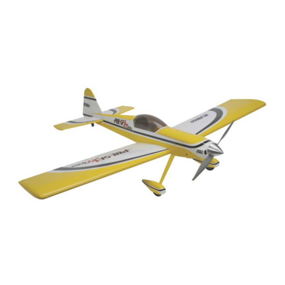
Table of Contents Introduction E-flite’s Pulse™ XT 25e is a 25-size electric version of the classic Hangar 9 Introduction..................... 2 ® Pulse 40 XT. This is a great flying sport ARF that’s perfect for intermediate Specifications..................2 pilots and sport fliers who want to fly an airplane that’s more aerobatic than Using This Manual..................3... -
Page 3: Using This Manual
Using This Manual Kit Contents This manual is divided into sections to make assembly of the model easier to understand and to provide breaks between each major section. In addition, check boxes have been placed next to each step to keep track of each step completed. -
Page 4: Required Equipment
11/64 in (4.5mm) drill bit Flat file Motor Drill The Pulse XT 25e is designed to accept either the E-flite Power 25 or Power 32 Ruler Brushless Outrunner motors and comes complete with the hardware for either 1.5mm Allen wrench (included with EFLA500) installation. -
Page 5: Fuselage Assembly
Landing Gear Assembly and Installation Ο 2. Use a 7/64” balldriver to install the landing gear on the fuselage with two 6-32” x 1/2” socket head bolts and #6 steel washers. The landing gear has a slight sweep and it should be installed on the model angled forward. Required parts: Threadlock may be used to prevent the bolts from loosening in flight. - Page 6 Ο Ο 4. Using a 1/16 in (1.5mm) drill bit in a pin drill, drill two holes where marked on the wheel pant. Apply a drop of thin CA in each hole to strengthen the wood. An accurate method of aligning the wheel pants to the fuselage is to level the fuselage with a block under the rear end, then support the wheel pant with another block while marking the location holes for the attachment screws with a felt-tip marker.
-
Page 7: Tail Installation
Tail Installation Ο 2. Slide the vertical stabilizer into place. It will be necessary to deflect the rudder to the right in order for the rudder horn to clear the elevator. The 4-40 rods will pass through the horizontal stabilizer and the fuselage. The forward Required Parts end of the vertical stabilizer assembly will slide over the turtledeck tab, and the Fuselage... -
Page 8: Fuselage Servo Installation
Fuselage Servo Installation Ο Ο 2. Using a 1/16 in (1.5mm) drill bit in a pin drill, drill the four mounting holes for the rudder and elevator servos. Apply a small drop of thin CA to each hole after drilling to strengthen the wood. Required Items (2) Servos and hardware (2) 23 5/8”... - Page 9 Ο Ο 4. Remove the servo arm using a #1 philips screwdriver. Using sidecutters, trim three of the arms from a standard four arm servo horn, leaving one long arm. Drill a 5/64 in (2mm) hole in the outermost hole using a pin drill. Center the servo using a JR MatchMaker or your radio system, and install the arm as shown using a #1 Philips screwdriver.
- Page 10 Ο Ο 6. Attach the clevises to the control horn on the elevator at the third hole from the mounting surface, and on the rudder at the second hole from the mounting surface. Do not install the silicone keepers at this time. We will do that later in construction on Page 27.
-
Page 11: Receiver Installation
#1 Philips screwdriver Threadlock N N o o t t e e : : Your E-flite Pulse XT 25e has been designed to accept the Power 25 and Power 32 motors. We have flown the model on wheels and floats with both motors. - Page 12 Ο 2. Using a 3/32” balldriver, install the motor on the firewall with four 4-40 Ο 4. Install the battery with two hook and loop straps. Slots are provided on x 1/2" socket head bolts. The motor wires should exit towards the bottom of the floor of the battery compartment for the straps to pass through.
-
Page 13: Motor And Battery Installation - Power 32
3/4" socket head bolts and four 4mm aluminum spacers. The motor wires should exit towards the bottom of the fuselage. You may use threadlock to prevent these screws from vibrating loose in flight. Required Parts E-flite Power 32 Motor with hardware E-flite 60A ESC E-flite Battery Propeller (4) 4-40 x 3/4"... - Page 14 Should you find that the rotation direction of your E-flite Power Brushless Outrunner is opposite to that needed, reversing it is just a matter of switching any two of the motor wires.
-
Page 15: Cowling, Propeller And Spinner Installation
Cowling, Propeller and Spinner Installation Ο 2. The spinner backplate requires the hole to be enlarged to suit the propeller adapter. For a snug fit on the prop adapter the hole should be approximately 9.5mm diameter. This is best done with a tapered reamer. Required Parts Proceed carefully and check the fit on the shaft as you enlarge the hole. - Page 16 Ο 4. Install the spinner cone using a #1 Philips screwdriver and the supplied Philips head screws. An alternate method to drilling completely through the spinner backplate is to grind only the relief necessary to clear the propeller adapter hub.This can be done by hand using a straight cutter in a Dremel rotary tool.
-
Page 17: Wing Assembly
Wing Joining Ο Ο 2.. Upon installation, approximately 5/16” to 3/8” of the dowel should protrude from the leading edge of the wing. Required Parts Wing halves (L and R) (2) dihedral joiners (2) leading edge dowels (2) 6-32 x 1” socket head bolts (2) #6 steel washers Required Tools and Adhesives Low-tack tape... - Page 18 Ο 4. Apply low-tack tape to the upper and lower surfaces of the center of the Ο 6. 12-minute epoxy is used to install the dihedral joiners and join the wing. wing panels as shown. This will allow for easy clean up of any excess glue and Glue the two dihedral joiners to each other.
-
Page 19: Aileron Servo Installation
Aileron Servo Installation. Ο 8. Install the dihedral joiners in one wing slot and slide the other wing panel onto the joiner. Wipe off any excess epoxy that squeezes out of the joint with rubbing alcohol and a paper towel. Required Parts (2) servos and hardware Using a 7/64”... - Page 20 Ο 2. A string is provided in each wing half to draw the aileron lead through Ο Ο 4. Using a 1/16 in (1.5mm) drill bit in a pin drill, drill the four mounting the wing. Attach the end of the string to the aileron servo lead and pull it holes for each aileron servo.
- Page 21 Ο Ο 6. Using a #1 Philips screwdriver remove the servo horn. Using sidecutters Ο Ο 8. Center the aileron servo using your radio or JR MatchMaker. Attach remove three of the four arms, leaving one long arm. Using a pin drill, enlarge the clevis to the aileron horn at the third hole from the surface and mark the the outermost hole to 5/64 in (2mm) to accept the pushrod.
-
Page 22: Canopy And Cooling Exit Scoop Installation
Canopy and Cooling Exit Scoop Ο 2. Follow the same procedure to attach the cooling exit scoop on the lower fuselage behind the wing in the location shown. Note that the opening faces towards the rear of the model. Required Parts Fuselage Canopy Cooling Exit Scoop... -
Page 23: Optional Float Installation
3mm x 12mm sheet metal screws. For the two floats a total of four brackets, four spacers and sixteen screws are required. Required parts: E-flite fiberglass 25-size Float Set Sullivan 36” flex cable Pulse XT 25e (assembled) (4) 1/8”... - Page 24 Ο Ο 4. Use a file or rotary tool to make a 1/4” wide flat on the top of each of Ο Ο 5. Attach the floats using four 5/32” wheel collars and four 3mm the four axles. The flat should be located approximately 9/16” (14mm) setscrews using the 1.5mm Allen wrench provided in the float kit.
- Page 25 Ο 7. Install the rudder assembly, steering arm and pushrod connector on the Ο 9. The Sullivan flex cable and tube need to be cut to length prior to nylon bracket. Refer to pages 12 and 13 in the Float Set assembly manual for installation.
- Page 26 Ο 11. Use the two remaining full brass straps to attach the pushrod tube to the Ο 12. Attach the water rudder cable housing to the left float mount strut using left side of the Pulse fuselage. Locate the straps as shown in the picture below the cable tie provided in the Float Set hardware bag.
-
Page 27: Flight Preparation
Flight Preparation Control Throws Use a ruler to set the control throws for the ailerons, rudder and elevator. The position of the pushrod can be altered at either the servo or control surface to Control Directions adjust the amount of control throw. Moving the pushrod closer to the center of 1. -
Page 28: Center Of Gravity
Preflight Center of Gravity (CG) The recommended center of gravity range for the Pulse XT 25e is 2.5 - 3.0” Battery Charging (63 - 76mm) behind the leading edge of the wing. Before making this Use the recommended charger for the batteries being used in your radio and measurement ensure that the model is in a ready-to-fly state, with all model, and follow the charging instructions. -
Page 29: Optional Items
E-flite quick-mount floats are designed specifically for 25-size airplanes that voltage differences during charge EFLC505). - Page 30 E-flite Power Meter DX6i 6-Channel Radio by Spektrum The E-flite Power Meter is designed for inline monitoring of Volts, Amps, Watts, The 6-channel DX6i uses the same DSM2™ technology found in the and Capacity, based on the mode you select to display on the digital LCD Spektrum™...
-
Page 31: Lithium Polymer Battery Pack Information
(see Disposal E-flite, Horizon Hobby, Inc., its retailers, and any other representatives, assume Instructions). absolutely no liability for use of these products or failure to comply with the •Use a specific Lithium Polymer charger only. -
Page 32: Instructions For Disposal Of Weee By Users In The European Union
Additional Information and Guidelines 6. Use fire-safe container to deliver battery to a recycling center authorized for 1. Battery temperature is the best indicator for safety. The E-flite LiPo battery’s Lithium Polymer batteries. Please note that not all battery recycling services temperature should never drop below 32 degrees Fahrenheit or go above 130 include LiPo’s. -
Page 33: Ama National Model Aircraft Safety Code
AMA National Model Aircraft Safety Code RADIO CONTROL 1. All model flying shall be conducted in a manner to avoid over flight of GENERAL unprotected people. 1. A model aircraft shall be defined as a non-human-carrying device capable 2. I will have completed a successful radio equipment ground-range check of sustained flight in the atmosphere. -
Page 34: Warranty Information
Warranty Period: Damage Limits: Exclusive Warranty- Horizon Hobby, Inc., (Horizon) warranties that the HORIZON SHALL NOT BE LIABLE FOR SPECIAL, INDIRECT OR Products purchased (the "Product") will be free from defects in materials and CONSEQUENTIAL DAMAGES, LOSS OF PROFITS OR PRODUCTION OR workmanship at the date of purchase by the Purchaser. - Page 35 Inspection or Repairs Electronics and engines requiring inspection or repair should be shipped to the If this Product needs to be inspected or repaired, please call for a Return following address: Merchandise Authorization (RMA). Pack the Product securely using a shipping carton.
- Page 36 © 2008 Horizon Hobby, Inc. 4105 Fieldstone Road Champaign, Illinois 61822 (877) 504-0233 horizonhobby.com E-fliteRC.com...