Table of Contents
Advertisement
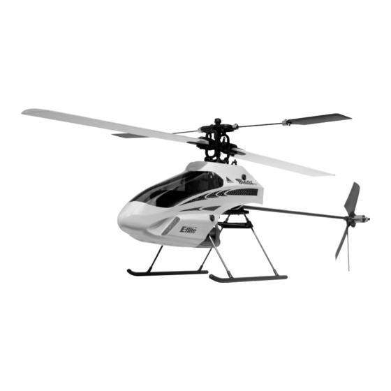
Specifications
Length . . . . . . . . . . . . . . . . . . . . . . . 20.63 in (524mm)
Height . . . . . . . . . . . . . . . . . . . . . . . 7.13 in (181mm)
Main Rotor Diameter . . . . . . . . . . . . . 20.75 in (527mm)
Tail Rotor Diameter . . . . . . . . . . . . . . 5.88 in (149mm)
Weight RTF w/Ni-MH Battery . . . . . . . 11.4 oz (325 g)
Main Motor . . . . . . . . . . . . . . . . . . . . 370 (included)
Tail Motor . . . . . . . . . . . . . . . . . . . . . N30 (included)
Battery . . . . . . . . . . . . . . . . . . . . . . . 9.6V 650mAh Ni-MH (included)
Transmitter . . . . . . . . . . . . . . . . . . . . FM 6-Channel w/CCPM Mixing (included)
On-Board Electronics . . . . . . . . . . . . . 4-in-1 Receiver/Mixer/ESC/Gyro (included)
Servo . . . . . . . . . . . . . . . . . . . . . . . . EFLRS75 High-Speed, High-Torque (3 included)
Advertisement
Table of Contents

Related Manuals for E-FLITE Blade CP


Summary of Contents for E-FLITE Blade CP
-
Page 1: Specifications
Specifications Length ..... . . 20.63 in (524mm) Height ..... . . 7.13 in (181mm) Main Rotor Diameter . -
Page 2: Table Of Contents
Gear Set [EFLH1128] before attempting your first flights), experienced pilots will enjoy many of the outstanding features that have the Blade CP flying in no time such as pre-installed main and tail motors, 4-in-1 control unit with receiver mixer ESCs and gyro, and high-speed, high-torque S75 sub-micro servos. With the included 6-channel FM transmitter featuring servo reversing, CCPM mixing and idle up flight mode switch, you’ll have precise control... -
Page 3: Warning
RC applications. All manufacturer’s instructions and warnings must be followed closely. Mishandling of Li-Po batteries can result in fire. Additional Required Equipment Only 8 “AA” batteries are required to complete your Blade™ CP. Blade CP RTF Contents Item Description Blade CP RTF Airframe... -
Page 4: Warranty Information
2.0–2.5 hours (faster “quick charge” AC and DC peak detection chargers are also available, see below). To ensure your battery is near fully discharged before charging, it is best to fly until your Blade CP will no longer maintain hover, at which point you will need to allow the battery to cool before placing it on the charger. Be certain to monitor the charge process, as batteries that are not fully discharged may be fully charged in less than 2.0–2.5 hours time. -
Page 5: Lithium Polymer Battery Upgrade Recommendations
Note: Li-Po batteries should not be discharged to below 3V per cell under load. In the case of 3-cell packs as used for the Blade CP, you will not want to allow the Li-Po battery to fall below 9V during flight. -
Page 6: Recommended Power System And Main Blade Configurations
Recommended Power System and Main Blade Configurations When using the recommended main motor, pinion, heat sink, battery and main blade configurations below, we have experienced very good main motor life (better than any other models in this class). We have main motors in stock and Aerobatic Enhancement Kit equipped models with more than 100 flights that continue to perform very well. - Page 7 Recommended Power System and Main Blade Configurations (continued) Tail Motor: When using the recommended heat sink and battery configurations below, we have experienced very good tail motor life (better than any other models in this class due to the use of a specially designed N30 motor). We have tail motors in stock and Aerobatic Enhancement Kit equipped models with more than 100 flights that continue to perform very well.
-
Page 8: Installing Transmitter Batteries
Installing Transmitter Batteries Install 8 new “AA” batteries in the included transmitter. Installing the Flight Battery Use the included hook and loop material for mounting the Ni-MH battery pack. You should also use the included rubber bands for the most secure attachment of the battery to the helicopter. Hook and Loop... -
Page 9: Center Of Gravity
Center of Gravity Once the battery has been properly installed and secured, you will need to check the helicopter’s center of gravity. With the canopy installed, lift the helicopter by the flybar with the flybar positioned perpendicular to the tail boom. Slide the battery support and battery forward or rearward as required to achieve a slightly nose down or perfectly level helicopter position. - Page 10 Control Test (continued) Turn the transmitter on first, and lower the throttle stick completely. Plug the battery into the battery lead of the 4-in-1 unit. Position the helicopter to view it from the left or right side. Move the left-hand stick up and down to check the collective pitch control.
- Page 11 Control Test (continued) Again viewing the helicopter from the left or right side, move the right-hand stick forward and aft to check elevator pitch control. When the stick is pushed forward, the swashplate should also tilt forward. With the stick pulled back, the swashplate will tilt toward the rear.
- Page 12 Control Test (continued) Viewing the helicopter from the rear (tail boom toward you), move the right-hand stick left and right to check aileron roll control. When the stick is pushed to the left, the swashplate should also tilt left. With the stick pushed right, the swashplate will tilt to the right.
- Page 13 Call Horizon’s Product Support staff at 1-877-504-0233. If you have confirmed proper control operation of your Blade CP, reconnect the main and tail motor wires to the 4-in-1 unit, taking care to keep the proper polarity and location of each as they were before the test. The tail motor plug should be installed into the upper output slot of the 4-in-1 control unit with the positive lead to the top.
-
Page 14: 4-In-1 Control Unit Description, Arming And Adjustment
Remember, due to the relatively small size of the Blade CP, you will not want to fly it very far away from yourself in order to keep proper orientation. - Page 15 Until you have properly trimmed, adjusted and become familiar with the handling of the Blade CP, we suggest your first and any subsequent test flights be made outdoors in calm air), free of obstructions, and are clear of the rotor blades, you can safely power up the model.
-
Page 16: Tail Rotor Proportional Mix Trimmer Pot Description And Adjustment
Tail Rotor Proportional Mix Trimmer Pot Description and Adjustment After establishing a stable hover, you will first want to adjust the tail rotor proportional mixing. The “proportional” trimmer pot adjusts the amount of tail motor to main motor mixing. Proportional Trimmer Pot In hover, with the rudder trim centered and no rudder input, note which direction the nose of the helicopter is trying to spin. -
Page 17: Gyro Gain Trimmer Pot Description And Adjustment
Gyro Gain Trimmer Pot Description and Adjustment The “gain” trimmer pot adjusts the gain of the piezo gyro used to aid in keeping the tail of the helicopter straight while flying. Gain Trimmer Pot Pilots interested most in hovering-type maneuvers with very little forward flight and aerobatics may choose to have the gain set as high as possible (without making the tail twitch quickly from side to side), keeping the tail of the helicopter very solid during flight. -
Page 18: Normal And Idle Up Flight Modes
Idle Up Switch With the switch toggled toward the rear of the transmitter, the Blade CP will be flying in “normal mode.” In this flight mode, the throttle curve is linear from 0% to 100%, with a pitch range of 0 degrees to +10 degrees. (See Page 20 for additional data and graphics relating to the throttle and pitch curves preset for your Blade CP.) This is... -
Page 19: Throttle And Pitch Curve Adjustments
–10 to +10 degrees (See page 20 for additional data and graphics relating to the throttle and pitch curves pre-set for your Blade CP). This flight mode is preferred for forward flight, aerobatics and inverted flying (requires symmetrical main blades). -
Page 20: Programmed Curves For The Normal Flight Mode
���� �������������� �������������� Programmed Curves for the Idle Up (Stunt) Flight Mode Right from the box, your Blade CP transmitter has been programmed for the following throttle and pitch curves in the idle up (stunt) flight mode: �������� ����� ����... -
Page 21: Blade Tracking Adjustment
• Following the proper arming and start-up procedure previously listed in the “4-in-1 Control Unit Description, Arming and Adjustment” section, bring the main rotor blades of your Blade CP up to speed. You can check the blade tracking either on the ground or in the air at eye level. It might be a good idea to have an assistant on- hand to help sight the blades. -
Page 22: Flybar Paddle Tracking Adjustment
Blade Tracking Adjustment (continued) Blades In Track — No Adjustment Necessary Typically, not much adjustment should be necessary to properly track the main rotor blades. If significant adjustments are required, be sure to double-check the length of both pitch control links (they should be close to the same length) and also check the blades for warps or twists. -
Page 23: 2005 Official Ama National Model Aircraft Safety Code
2005 Official AMA National Model Aircraft Safety Code GENERAL 1) I will not fly my model aircraft in sanctioned events, air shows or model flying demonstrations until it has been proven to be airworthy by having been previously, successfully flight tested. 2) I will not fly my model higher than approximately 400 feet within 3 miles of an airport without notifying the airport operator. -
Page 24: Replacement Parts List
Replacement Parts List EFLH1100 . . . Blade CP RTF Electric Micro Heli EFLH1135 . . . Retaining Pin (6): BCP EFLH1101 . . . Blade CP ARF Replacement Airframe EFLH1136 . . . Canopy Mount & Grommet Set: BCP EFLH1017 . -
Page 25: Replacement And Optional Parts
Replacement and Optional Parts 4-in-1 Control Unit FM Crystal Set CH17, FM Crystal Set CH19, FM Crystal Set CH21, FM Crystal Set CH50, FM Crystal Set CH52, FM Crystal Set CH54, FM 72MHz: BCP 72.130: BCP 72.170: BCP 72.210: BCP 72.790: BCP 72.830: BCP 72.870: BCP... -
Page 26: Exploded View Parts Listing
Exploded View Parts Listing Exploded Exploded Included Included View Description View Description In Item In Item Reference (Quantity Required) Reference (Quantity Required) Number Number Number Number 001 ..Flybar Paddle (2) ... . . EFLH1150 035 . -
Page 27: Exploded View
Exploded View... - Page 28 © 2005 Horizon Hobby, Inc. 4105 Fieldstone Road Champaign, Illinois 61822 (877) 504-0233 www.E-fliteRC.com 7565.1...