
Related Manuals for E-FLITE Pitts Model 12 15e ARF


Summary of Contents for E-FLITE Pitts Model 12 15e ARF
-
Page 1: Specifications
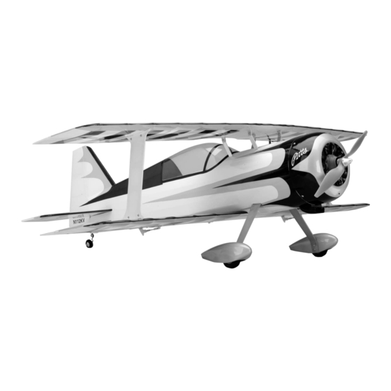
Pitts Model 12 15e ARF Assembly Manual Specifications Wingspan: 40 in (1015mm) Length: 39 in (990mm) Wing Area: 555 sq in (35.8 sq dm) Weight w/ Battery: 48–50 oz (1360–1420 g) Weight w/o Battery: 43–45 oz (1220–1275 g) -
Page 2: Table Of Contents
Introduction Specifications ..............1 The E-flite ® Pitts Model 12 15e ARF is a 3D-capable, sport Introduction ................. 2 replica of one of aviation’s hottest aerobatic machines. Designed Scale Outline and History ............ 2 by veteran world class competitor, Quique Somenzini, it will Using the Manual .............. -
Page 3: Using The Manual
AR6200 DSM2 6-Channel Receiver Ultralite EFL2558 Canopy (for DX7 only) SPM6070 AR7000 DSM2 7CH Rx (for DX7 only) JSP20030 MC35 Micro Servo (4) EFLREX6L 6-inch lightweight extension (2) EFLREX9L 9-inch lightweight extension (2) E-flite Pitts Model 12 15e ARF Assembly Manual... -
Page 4: Important Information About Motor Selection
Phillips screwdriver: #0, #1 EFLC3005 Celectra 1- to 3-Cell Li-Po Charger Masking tape Canopy glue This is a high-power performance setup for sport flights. Rotary tool 3mm ball driver Pin drill Side cutters E-flite Pitts Model 12 15e ARF Assembly Manual... -
Page 5: Notes Regarding Servos And Esc
Horizon before shipment. Horizon Hobby, Inc., (Horizon) warranties that the Products purchased (the “Product”) will be free from defects in materials and workmanship at the date of purchase by the Purchaser. E-flite Pitts Model 12 15e ARF Assembly Manual... -
Page 6: Damage Limits
Provided warranty conditions have been met, your Product will be repaired or replaced free of charge. Repair or replacement decisions are at the sole discretion of Horizon Hobby. E-flite Pitts Model 12 15e ARF Assembly Manual... -
Page 7: Non-Warranty Repairs
• Moisture causes damage to electronics. Avoid water exposure Champaign, Illinois 61822 to all equipment not specifically designed and protected for this purpose. Please call 877-504-0233 with any questions or concerns regarding this product or warranty. E-flite Pitts Model 12 15e ARF Assembly Manual... -
Page 8: Hinging The Control Surfaces
T-pins will rest against the edge of the wing. Note: It is suggested to drill the CA tunnel in the top and bottom wings, ailerons, stabilizer, elevator, rudder and fuselage at this time as well. E-flite Pitts Model 12 15e ARF Assembly Manual... - Page 9 Note: Placing a #11 hobby knife blade between the wing trailing edge and the leading edge of the aileron will ensure you will get maximum deflection without binding for 3D flight. E-flite Pitts Model 12 15e ARF Assembly Manual...
- Page 10 8. Use six CA hinges to attach the stabilizer to the elevator. Again, follow the hinging process as described. 7. Install the aileron in the top wing at this time. Follow the hinging procedure as described for the bottom wing. E-flite Pitts Model 12 15e ARF Assembly Manual...
-
Page 11: Wing Installation
3. Remove the covering for the wing bolt on the bottom wing. Place the pre-covered wing bolt support in position and trace around the support using a felt-tipped pen. E-flite Pitts Model 12 15e ARF Assembly Manual... - Page 12 7. Locate the two wing struts. Use the photo to determine in the fuselage. the top and bottom of the struts. Use a hobby knife to expose the holes for mounting the struts. E-flite Pitts Model 12 15e ARF Assembly Manual...
- Page 13 2mm x 10mm machine screws, four 2mm washers and four 2mm nuts. 10. Secure the cabane struts to the top wing using four 2mm x 10mm machine screws, four 2mm washers and four 2mm nuts. E-flite Pitts Model 12 15e ARF Assembly Manual...
-
Page 14: Stabilizer Installation
3. Make sure the stabilizer is parallel to the wings as shown. Lightly sand the slot in the fuselage as necessary to correct for any misalignment. E-flite Pitts Model 12 15e ARF Assembly Manual... - Page 15 Hint: Use either a hot knife or soldering iron to cut the covering, as this will reduce the amount of pressure needed to cut the covering, and in turn, reduce the chances of cutting into the underlying wood. E-flite Pitts Model 12 15e ARF Assembly Manual...
-
Page 16: Rudder Installation
Lightly sand the bottom of the fin until the alignment is correct. Use 30-minute epoxy to glue the fin to the fuselage. Check the alignment to make sure it does not change position during the curing process. E-flite Pitts Model 12 15e ARF Assembly Manual... - Page 17 5. Slide the tail wheel bracket onto the tail gear assembly. of the rudder. Use 6-miniute epoxy to glue the tail wheel assembly into the rudder. Use tape to hold the wire in position until the epoxy fully cures. E-flite Pitts Model 12 15e ARF Assembly Manual...
-
Page 18: Landing Gear Installation
7. Use two #2 x 1/2-inch sheet metal screws to attach the tail gear bracket to the fuselage. Make sure the alignment does not bind against the wire when operating the rudder. E-flite Pitts Model 12 15e ARF Assembly Manual... - Page 19 Use a 3mm wheel collar and setscrew to secure to the fuselage. the screw in the wheel. Use threadlock on the setscrew to prevent it from vibrating loose. E-flite Pitts Model 12 15e ARF Assembly Manual...
- Page 20 Use a 3mm nut and 3mm washer to attach the wheel/wheel pant to the landing gear. Use threadlock on the nut to prevent it from vibrating loose. 10. Repeat Steps 5 through 9 for the remaining wheel and wheel pant. E-flite Pitts Model 12 15e ARF Assembly Manual...
-
Page 21: Radio Installation
9-inch (228mm) servo extension (2) 1. Secure a 9-inch (228mm) servo extension to the servo lead as shown. Use a commercially available connector or some thread to secure the connection. E-flite Pitts Model 12 15e ARF Assembly Manual... - Page 22 6. Attach the control horn using two 2mm x 10mm machine screws and a control horn backplate. 4. Use a pin drill with a 5/64-inch (2mm) drill bit to drill the holes for the control horn screw. E-flite Pitts Model 12 15e ARF Assembly Manual...
- Page 23 Mark the pushrod with a felt-tipped pen where it crosses the outside hole on the servo arm. E-flite Pitts Model 12 15e ARF Assembly Manual...
- Page 24 Make the position of the servo on the cover. E-flite Pitts Model 12 15e ARF Assembly Manual...
- Page 25 1/16-inch (1.5mm) drill bit and drill. 16. Tie the string to the servo lead. E-flite Pitts Model 12 15e ARF Assembly Manual...
- Page 26 18. Use a drill and 1/16-inch (1.5mm) drill to drill a hole at each of the corners of the servo cover and into the supports. Use four 2mm x 6mm sheet metal screws to secure the servo cover to the wing. E-flite Pitts Model 12 15e ARF Assembly Manual...
-
Page 27: Motor Installation
Use threadlock on the screws to prevent them from vibrating loose. 3. Attach the motor to the firewall using the hardware provided with the motor. Use threadlock on the screws to prevent them from vibrating loose. E-flite Pitts Model 12 15e ARF Assembly Manual... - Page 28 Note: Never check the motor rotation on the bench with the propeller installed. The plane could move and cause serious injury. Always check the motor without the propeller to avoid injury. E-flite Pitts Model 12 15e ARF Assembly Manual...
- Page 29 Use 6-minute epoxy to glue the dummy radial engine inside the cowling. E-flite Pitts Model 12 15e ARF Assembly Manual...
-
Page 30: Final Detail Installation
It will be black in color as well, not white as depicted in the photo. These changes were made to ensure the accuracy of the full scale Pitts model 12 was maintained. E-flite Pitts Model 12 15e ARF Assembly Manual... - Page 31 3D flight. 1. Attach the flying wires to the fin and stabilizer using 2mm x 10mm machine screws and 2mm nuts. Use threadlock on the nuts to prevent them from vibrating loose. E-flite Pitts Model 12 15e ARF Assembly Manual...
-
Page 32: Control Throws
Note: The clear fin extensions are included to enhance the 3D flight envelope. Quique designed these and found them to help the model in inverted harriers as well as extreme yaw control during other high alpha manevers. E-flite Pitts Model 12 15e ARF Assembly Manual... -
Page 33: Center Of Gravity
After the first flights, the CG position can be adjusted for your The E-flite power plant delivers enough watts to make the Pitts personal preference. climb and accelerate with authority giving the Pitts the look of a true unlimited performer. -
Page 34: Preflight
Preflight Flying Your Pitts Model 12 15e ARF Flying the Pitts Model 12 15e ARF is about as fun as it can get. Check Your Radio A very light wing loading and extreme control throws make for Before going to the field, be sure that your batteries are fully some exciting 3D flying. -
Page 35: 2007 Official Ama National Model Aircraft Safety Code
Only personnel involved with flying the aircraft are allowed at or in front of the flight line. Intentional flying behind the flight line is prohibited. E-flite Pitts Model 12 15e ARF Assembly Manual... - Page 36 © 2007 Horizon Hobby, Inc. 4105 Fieldstone Road Champaign, Illinois 61822 (877) 504-0233 horizonhobby.com E-fliteRC.com 10491...