
Related Manuals for Netopia R5000


Summary of Contents for Netopia R5000
- Page 1 ™ Netopia R5000 Series Routers R5100 Serial Router R5200 DDS Router R5300 T1 Router User’s Reference Guide...
- Page 2 This manual and any associated artwork, software, and product designs are copyrighted with all rights reserved. Under the copyright laws such materials may not be copied, in whole or part, without the prior written consent of Netopia, Inc. Under the law, copying includes translation to another language or format.
-
Page 3: Table Of Contents
Welcome to the Netopia R5000 Series Router User’s Reference Guide. This guide is designed to be your single source for information about your Netopia R5000 Series Router. It is intended to be viewed on-line, using the powerful features of the Adobe Acrobat Reader. The information display has been designed to present the maximum information in the minimum space on your screen. - Page 4 User’s Reference Guide Readying computers on your local network... 4-1 Connecting to an Ethernet network... 4-3 10Base-T... 4-3 Adding an external modem ... 4-4 Connecting to a LocalTalk network ... 4-5 Chapter 5 — Setting up your Router with the SmartStart Wizard 5-1 Before running SmartStart ...
- Page 5 Part II: Advanced Configuration Chapter 8 — WAN and System Configuration ...8-1 WAN configuration... 8-1 Line configuration for a Serial line ... 8-2 Line configuration for a DDS line ... 8-3 Line configuration for a T1 line ... 8-4 Configuring Frame Relay ... 8-6 Easy Setup Frame Relay screens...
- Page 6 User’s Reference Guide Security ... 8-36 Upgrade feature set ... 8-36 Logging ... 8-36 Installing the Syslog client ... 8-37 Chapter 9 — IP Setup and Network Address Translation ...9-1 Network Address Translation features ... 9-1 Using Network Address Translation ... 9-3 Associating port numbers with nodes ...
- Page 7 Chapter 11 — AppleTalk Setup...11-1 AppleTalk networks ... 11-1 AppleTalk protocol ... 11-1 MacIP... 11-3 AURP... 11-3 Routers and seeding ... 11-3 Installing AppleTalk ... 11-4 Configuring AppleTalk ... 11-6 EtherTalk setup ... 11-6 LocalTalk setup ... 11-7 AURP setup ... 11-8 Chapter 12 —...
- Page 8 viii User’s Reference Guide Router Budget Configuration page ... 12-25 Connection Budgets page ... 12-26 Connection Budget Configuration page... 12-27 Budget Statistics page ... 12-28 Event History pages ... 12-29 Chapter 13 — Security ...13-1 Suggested security measures ... 13-1 User accounts ...
- Page 9 Firewall design rules... 13-32 Filter basics ... 13-35 Example filters ... 13-36 Chapter 14 — Utilities and Diagnostics ...14-1 Ping ... 14-2 Trace Route... 14-5 Telnet client... 14-6 Disconnect Telnet console session ... 14-7 Factory defaults... 14-7 Transferring configuration and firmware files with TFTP... 14-8 Updating firmware ...
- Page 10 Tips and rules for distributing IP addresses... B-9 Nested IP subnets ... B-11 Broadcasts... B-13 Packet header types... B-13 Appendix C — Understanding Netopia NAT Behavior...C-1 Network configuration... C-1 Background ... C-1 Exported services ... C-5 Important notes ... C-6 Configuration ...
- Page 11 Contents Index ...Index-1 Limited Warranty and Limitation of Remedies ...1...
- Page 12 User’s Reference Guide...
- Page 14 User’s Reference Guide...
-
Page 15: Chapter 1 - Introduction
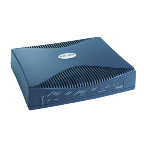
The Netopia R5000 Series Router line consists of the R5100 Serial Router, the R5200 DDS Router, and the R5300 T1 Router. Each is a full-featured, stand-alone, multiprotocol router for connecting diverse local area networks (LANs) to the Internet and other remote networks. -
Page 16: Configuration
NAT on the same physical or tunneled connection. This guide is designed to be your single source for information about your Netopia R5000 Series Router. It is intended to be viewed on-line, using the powerful features of the Adobe Acrobat Reader. The information display has been deliberately designed to present the maximum information in the minimum space on your screen. -
Page 17: Chapter 2 - Setting Up Internet Services
Note: Some companies act as their own ISP. For example, some organizations have branch offices that can use the Netopia R5000 Series to access the Internet via the main office. If you install the Netopia R5000 Series in this type of environment, refer to the following sections for specific information you must receive from the network administrator to configure the Netopia R5000 Series properly. - Page 18 Check whether your ISP has the Netopia R5000 Series on its list of supported products that have been tested with a particular configuration. If the ISP does not have the Netopia R5000 Series on such a list, describe the Netopia R5000 Series in as much detail as needed, so your ISP account can be optimized. As appropriate, refer your ISP to Netopia’s Web site, http://www.netopia.com, for more information.
- Page 19 The number of Ethernet IP host addresses available with your account and the first usable IP host address in the address block The Ethernet IP address for your Netopia R5000 Series The Ethernet IP subnet mask address for your Netopia R5000 Series Setting Up Internet Services 2-3...
- Page 20 2-4 User’s Reference Guide...
-
Page 21: Chapter 3 - Making The Physical Connections
Cable length and network size limitations when expanding networks For small networks, install the Netopia R5000 Series Router near one of the LANs. For large networks, you can install the Netopia R5000 Series Router in a wiring closet or a central network administration site. - Page 22 You will need: A Windows 95 or 98–based PC or a Macintosh computer with Ethernet connectivity for configuring the Netopia R5000 Series Router. This may be built-in Ethernet or an add-on card, with TCP/IP installed and configured. See “Before running SmartStart” on page A wall outlet wired for a T1 (for the R5300) or DDS (for the R5200) connection or a connection to an external CSU/DSU or modem (for the R5100).
- Page 23 Making the Physical Connections 3-3 Identify the connectors and switches on the back panel and attach the necessary Netopia Router cables. The figure below displays the back of the Netopia R5100 Serial Router. Netopia R5100 back panel Serial Line port...
- Page 24 3-4 User’s Reference Guide The following table describes all of the Netopia R5000 Series Router back panel ports. Port Power port A mini-DIN8 power adapter cable connection. Serial Line 1 port A DB-15 serial port labelled Line 1 - Serial for your external CSU/DSU or modem (R5100 Serial router only) connection.
- Page 25 The figure below represents the Netopia R5000 Series Router status light (LED) panel. Netopia R5000 Series Router LED front panel WAN 1 The following table summarizes the meaning of the various LED states and colors: When this happens... The corresponding line passes supervisory traffic between...
- Page 26 3-6 User’s Reference Guide...
-
Page 27: Readying Computers On Your Local Network
“Routers and seeding” on page 11-3. See the later sections in this chapter for details on how to connect the Netopia R5000 Series to different types of networks. PC and Macintosh computers must have certain components installed before they can communicate through the Netopia R5000 Series. - Page 28 TCP/IP stacks must be configured with some of the same information you used to configure the Netopia R5000 Series. There are a number of TCP/IP stacks available for PC computers. Windows 95, 98, and NT include a built-in TCP/IP stack. See Macintosh computers use either MacTCP or Open Transport.
- Page 29 Ethernet port is in use. You can connect 10Base-T or 10/100 Ethernet devices to the Netopia R5000 Series Router. You can connect a standard 10Base-T Ethernet network to the Netopia R5000 Series Router using any of its available Ethernet ports.
-
Page 30: Pinouts For Auxiliary Port Modem Cable
Auxiliary connection port HD-15 (female) By default, the Auxiliary port on your Netopia R5000 Series is enabled for remote console-based management via an external modem. This means that all you have to do is connect your modem to the Auxiliary port and configure the router for any AT command string your modem requires in the Line Configuration screens under... - Page 31 HD-15 (female) Connect the male HD-15 end of the PhoneNET connector to the Auxiliary port on your Netopia R5000 Series. Connect the other end of the cable to your LocalTalk network. You can use only one connection on the Auxiliary port.
- Page 32 4-6 User’s Reference Guide...
-
Page 33: Chapter 5 - Setting Up Your Router With The Smartstart Wizard
Once you’ve connected your router to your computer and your telecommunications line and installed a web browser, you’re ready to run the Netopia SmartStart™ Wizard. The SmartStart Wizard will help you set up the router and share the connection. The SmartStart Wizard walks you through a series of questions and, based on your responses, automatically configures the router for connecting your LAN to the Internet or to your remote... -
Page 34: Configuring Tcp/Ip On Windows 95, 98, Or Nt Computers
The computer running SmartStart must be on the same Ethernet cable segment as the Netopia R5000 Series Router. Repeaters, such as 10Base-T hubs between your computer and the Netopia R5000 Series, are acceptable, but devices such as switches, 10/100 bridges, or other routers are not. - Page 35 The SmartStart Wizard presents a series of screens to guide you through the preliminary configuration of a Netopia R5000 Series. It will then create a connection profile using the information you supply to it. Welcome screen. The first screen welcomes you to the SmartStart Wizard configuration utility.
- Page 36 If the test fails, the wizard displays an error screen. If the test fails, check the following: Check your cable connections. Be sure you have connected the router and the computer properly, using the correct cables. Refer to the Step 1 “Connect the Router” sheet in your Netopia R5000 Series documentation folio.
- Page 37 When the test is successful, SmartStart presents you with the Additional Configuration screen. If you have a router that has a permanent unswitched connection to your ISP, such as a Netopia R5000 Series Router, the Additional Configuration screen appears. You may want to do additional configuration to customize your network environment.
- Page 38 It is also found in your documentation folio. Note: Forcing a new IP address may turn off the Netopia R5000 Series’s IP address serving capabilities, if you assign an IP address and subnet mask outside the router’s current IP address serving pool.
- Page 39 If you configure your Netopia R5000 Series using SmartStart, you can accept the dynamic IP address assigned by your router. The Dynamic Host Configuration Protocol (DHCP) server, which enables dynamic addressing, is enabled by default in the router. If your PC is not set for dynamic addressing, SmartStart will offer to do this for you if you select the Easy setup option.
- Page 40 5-8 User’s Reference Guide If you are manually configuring for a fixed or static IP address, perform the following: Go to Start Menu/Settings/Control Panels and double click the Network icon. From the Network components list, select the Configuration tab. Select TCP/IP-->Your Network Card. Then select Properties. In the TCP/IP Properties screen (shown below), select the IP Address tab.
- Page 41 Click on the Gateway tab (shown below). Under “New gateway,” enter 192.168.1.1. Click Add. This is the Netopia R5000 Series’s pre-assigned IP address. Click OK in this window and the next window. When prompted, reboot the computer. Note: You can also use these instructions to configure other computers on your network with manual or static IP addresses.
- Page 42 R5000 Series to assign IP addresses to your Macintoshes, you must be running Open Transport, standard in MacOS 8 and optional in earlier system versions. You can have your Netopia R5000 Series dynamically assign IP addresses using MacTCP; however, to do so requires that the optional AppleTalk kit be installed which can only be done after the router is configured.
- Page 43 If you are manually configuring for a fixed or static IP address, perform the following: Go to the Apple menu. Select Control Panels and then TCP/IP or MacTCP. With the TCP/IP window open, go to the Edit menu and select User Mode. Choose Advanced and click OK. Or, in the MacTCP window, select Ethernet and click the More button.
- Page 44 If you want to use MacIP to dynamically assign IP addresses to the Macintosh computers on your network you must install the optional AppleTalk feature set kit. Note: You cannot use MacIP dynamic configuration to configure your Netopia R5000 Series Router because you must first configure the router in order to enable AppleTalk.
- Page 45 Restart the computer. Note: More information about configuring your Macintosh computer for TCP/IP connectivity through a Netopia R5000 Series can be found in Technote NIR_026, “Open Transport and Netopia Routers,” located on the Netopia Web site. Setting up your Router with the SmartStart Wizard 5-13...
- Page 46 5-14 User’s Reference Guide...
-
Page 47: Chapter 6 - Console-Based Management
Console-based management is a menu-driven interface for the capabilities built into the Netopia R5000 Series routers. Console-based management provides access to the full range of features that the router supports. You can customize these features for your individual setup. This chapter describes how to access the console-based management screens. - Page 48 The Quick View menu displays at a glance current real-time operating information about your router. See “Quick View status overview” on page 12-1 Features of the Netopia R5000 Series can be configured through the console screens. If you initially use the SmartStart Wizard, the application will automatically connect you to the console-based management screens via Telnet.
- Page 49 If you connect a Macintosh computer, you can use the NCSA Telnet program supplied on the Netopia R5000 Series CD. You install NCSA Telnet by simply dragging the application from the CD to your hard disk. You can perform all of the system configuration activities for your Netopia R5000 Series through a local serial console connection using terminal emulation software, such as HyperTerminal provided with Windows 95 on the PC, or ZTerm, included on the Netopia CD, for Macintosh computers.
- Page 50 6-4 User’s Reference Guide Launch your terminal emulation software and configure the communications software for the values shown in the table below. These are the default communication parameters that the Netopia R5000 Series uses. Parameter Terminal type Data bits Parity...
-
Page 51: Chapter 7 - Easy Setup
This chapter describes how to use the Easy Setup console screens on your Netopia R5000 Series Router. After completing the Easy Setup console screens, your router will be ready to connect to the Internet or another remote site. Using four Easy Setup console screens, you can: Modify a connection profile for your router for the connection to your ISP or remote location... -
Page 52: The T1 Line Configuration Screen
If you do not see the Main Menu, verify that: The computer used to view the console screen has its serial port connected to the Netopia R5000 Series’s Console port or an Ethernet connection to one of its Ethernet ports. See your router”... - Page 53 Select Data Rate (kbps) and press Return. From the pop-up menu, select a fixed data rate for your digital line or select Auto. The Auto setting allows your Netopia Router to determine the data rate of your serial line at the time of circuit activation. Press Return.
- Page 54 7-4 User’s Reference Guide The T1 Line Configuration screen appears. Line Encoding... Framing Mode... Number of DS0 Channels: First DS0 Channel: Channel Data Rate... Data Link Encapsulation... TO MAIN MENU Enter Information supplied to you by your telephone company. Select Line Encoding and press Return. From the pop-up menu, highlight the encoding your telephone ser- vice provider uses: B8Zs or AMI.
- Page 55 DDS/ADN line connection to transmit at. The data rate choices are Automatic (the default), 56 kbps, and 64 kbps. Press Return. Note: As noted above, DDS/ADN Netopia Routers may run 56 kbps or 64 kbps data rates on permanent circuits. If you accept the default, Automatic, the router will hunt between modes until it can determine what the telephone company has provisioned your DDS/ADN line for.
-
Page 56: Easy Setup Profile Screen
Router’s connection to a specific remote destination, usually your ISP or a corporate site. On a Netopia R5000 Series Router you can add up to 15 more connection profiles, for a total of 16, although you can only use one at a time. -
Page 57: Ip Easy Setup
Note: For more Easy Setup options, see the next section. For more Frame Relay configuration options see “Configuring Frame Relay” on page The IP Easy Setup screen is where you enter information about your Netopia Router’s: Ethernet IP address Ethernet Subnet mask... -
Page 58: Easy Setup Security Configuration
If you do not enter a Default IP Gateway value, the router defaults to the remote IP address you entered in the Easy Setup connection profile. If the Netopia Router does not recognize the destination of any IP traffic, it forwards that traffic to this gateway. - Page 59 The final step in configuring the Easy Setup console screens is to restart the Netopia R5000 Series, so that the configuration settings take effect. Select RESTART DEVICE. A prompt asks you to confirm your choice. Select CONTINUE to restart the Netopia Router and have your selections take effect.
- Page 60 7-10 User’s Reference Guide...
- Page 62 User’s Reference Guide...
-
Page 63: Configuring Frame Relay
This chapter describes how to use the console-based management screens to access and configure advanced features of your Netopia R5000 Series Router. You can customize these features for your individual setup. These menus provide a powerful method for experienced users to set up their router’s connection profiles and system configuration. - Page 64 Auto. (The data rates to choose from range from 56 kbps to the highest synchronized line speed.) The Auto setting allows your Netopia Router to determine the data rate of your serial line at the time of circuit activation. For an asynchronous modem, the only encapsulation is PPP. Press Return.
- Page 65 The data rate choices are 56 kbps and 64 kbps. The default is Automatic. Press Return. Note: DDS Netopia Routers can run 56 kbps or 64 kbps data rates on permanent circuits. You can alternately select Automatic, in which case the router will hunt between modes until it can determine what the telephone company has provisioned your DDS line for.
- Page 66 8-6 for more information. The T1 Line Configuration screen is where you enter the configuration parameters for your T1 line, in order for the Netopia Router to communicate with the physical connection. Line Encoding... Framing Mode... Transmit ANSI PRMs:...
- Page 67 For fractional T1, you can also specify in the check box whether the DS0 channels are contiguous or alternating. Select First DS0 Channel and enter the number of the first active DS0 channel you will be using. The default setting is 1 (one). Press Return. Note: You can change the First DS0 Channel number, which has a valid range from one to the maximum number minus the number of active channels.
-
Page 68: Easy Setup Frame Relay Screens
8-6 User’s Reference Guide Frame Relay is an alternative data link encapsulation method for use over unswitched connections. If this does not apply to your connection, you can skip the corresponding sections. You can specify Frame Relay as your data link encapsulation method in either of two ways: “Easy Setup Frame Relay screens”... - Page 69 The Line Configuration menu also offers the options of either PPP, HDLC, or Frame Relay as your data link encapsulation method. Main Menu Line Encoding... Framing Mode... Transmit ANSI PRMs: Number of DS0 Channels: First DS0 Channel: Buildout (-dB)... Channel Data Rate... Clock Source...
-
Page 70: Frame Relay Configuration
8-8 User’s Reference Guide If you chose Frame Relay as your data link encapsulation type you can now configure the Frame Relay options from the WAN Configuration menu. Return/Enter for WAN line configuration. From here you will configure yours and the remote sites' WAN information. From the WAN Configuration screen, select WAN Setup, then select the Frame Relay Configuration option and press Return. - Page 71 Select Congestion Management Enabled and toggle to Yes or No depending on whether you use this selection. Press Return. If Congestion Management is enabled, this option causes the Netopia Router to use in-bound FECNs (Forward Explicit Congestion Notification). This feature is designed to notify you that congestion avoidance procedures should be initiated where applicable for traffic in the same direction as the received frame.
-
Page 72: Frame Relay Dlci Configuration
WAN Configuration screen. If you need to configure your DLCIs, go to the next section. If you selected None as your LMI Type then you will need to manually configure your DLCIs. A Frame Relay DLCI is a set of parameters that tells the Netopia Router how to initially connect to a remote destination. - Page 73 Up/Down Arrow Keys to select, ESC to dismiss, Return/Enter to Edit. To modify a Frame Relay DLCI configuration, select Display/Change DLCIs in the Frame Relay DLCI Configuration screen. Select a DLCI Name from the table and press Return to go to the Change DLCI screen. The parameters in this screen are the same as the parameters in the Add DLCI screen.
- Page 74 This is accomplished by giving a DLCI Name to a DLCI Number. Select DLCI Enabled and toggle it to Yes to activate the profile. If you disable this profile, the Netopia Router will automatically disable and block access to a specific remote DLCI.
- Page 75 provider agrees to transfer from a given PVC (Permanent Virtual Circuit) or DLCI (Data Link Connection Identifier). The setting defaults to 64000, but you may modify the committed burst size by toggling the selection in the Use Default field to No. You can then enter a different committed burst size in the Value field.
-
Page 76: Creating A New Connection Profile
Configure a new Conn. Profile. Finished? On a Netopia R5000 Series Router you can add up to 15 more connection profiles, for a total of 16. Select Profile Name and enter a name for this connection profile. It can be any name you wish. For example: the name of your ISP. - Page 77 Address Translation Enabled: Local WAN IP Address: Remote IP Address: Remote IP Mask: Filter Set... Remove Filter Set Receive RIP: Toggle to Yes if this is a single IP address ISP account. Configure IP requirements for a remote network connection here. Toggle or enter any IP Parameters you require and return to the Add Connection Profile screen by pressing Escape.
- Page 78 8-16 User’s Reference Guide Toggle or enter any IPX Parameters you require and return to the Add Connection Profile screen by pressing Escape. For more information, see Select Datalink Options and press Return. The Datalink Options screen appears. The Datalink Options screen will vary depending on the data link encapsulation method you are using.
- Page 79 The PPP options screen for a switched interface appears as follows: Data Compression... Send Authentication... Send User Name: Send Password: Receive User Name: Receive Password: Maximum Packet Size: In this Screen you will configure the PPP/MP specific connection params. You can accept the defaults, or change them if you wish. You can also specify user name and password for both outgoing and incoming calls.
- Page 80 8-18 User’s Reference Guide For a switched connection only, select Telco Options and press return. the Telco Options screen appears. Note: For IDSL routers, which do not initiate dial-up connections, this option does not appear. Dial... Number to Dial: Alternate Site to Dial: Dial on Demand: Idle Timeout (seconds): Callback:...
- Page 81 If you want to view the Connection Profiles in your router, return to the WAN Configuration screen, and select Display/Change Connection Profile. The list of Connection Profiles is displayed in a scrolling pop-up screen. +-Profile Name---------------------IP Address----IPX Network-+ +------------------------------------------------------------+ | Easy Setup Profile | Profile 02 +------------------------------------------------------------+ Up/Down Arrow Keys to select, ESC to dismiss, Return/Enter to Edit.
-
Page 82: The Default Profile
8-20 User’s Reference Guide For R5100 SA and R5300 T1 models the Default Profile screen controls whether or not the communication link will come up without an explicitly configured connection profile. If you have an R5200 DDS model, you can skip this section. - Page 83 Return/Enter accepts * Tab toggles * ESC cancels. The Netopia R5000 Series Router always acts as a DHCP client on the communication link when using a Default Profile. The DHCP server will supply a local IP address and subnet mask. For a communication link, Network Address Translation (NAT) is enabled by default in the Default Profile.
-
Page 84: Ipx Parameters (Default Profile) Screen
8-22 User’s Reference Guide The IPX Parameters (Default Profile) screen allows you to configure various IPX parameters for connections established without an explicitly configured connection profile: NetBios Packet Forwarding: Path Delay: Incoming Packet Filter Set... Outgoing Packet Filter Set... Incoming SAP Filter Set... Outgoing SAP Filter Set... -
Page 85: Scheduled Connections (Switched Async Only)
Scheduled connections To go to the Scheduled Connections screen, select Scheduled Connections in the WAN Configuration screen. Main Menu Navigate from here to add/modify/change/delete Scheduled Connections. Configuration Scheduled Connections Display/Change Scheduled Connection... Add Scheduled Connection... Delete Scheduled Connection... WAN and System Configuration 8-23 Scheduled Connections... -
Page 86: Viewing Scheduled Connections
8-24 User’s Reference Guide Viewing scheduled connections To display a table of view-only scheduled connections, select Display/Change Scheduled Connection in the Scheduled Connections screen. Each scheduled connection occupies one row of the table. +-Days----Begin At---HH:MM---When----Conn. Prof. Name----Enabled-----+ +--------------------------------------------------------------------+ | mtWtfss 08:30PM +--------------------------------------------------------------------+ The first column in the table shows a one-letter representation of the Days of the week, from Monday (M or m) to Sunday (S or s). -
Page 87: Adding A Scheduled Connection
Adding a scheduled connection To add a new scheduled connection, select Add Scheduled Connection in the Scheduled Connections screen and press Return. The Add Scheduled Connection screen appears. Scheduled Connection Enable: How Often... Schedule Type... Set Weekly Schedule... Use Connection Profile... ADD SCHEDULED CONNECTION Scheduled Connections dial remote Networks on a Weekly or Once-Only basis. -
Page 88: Set Weekly Schedule
8-26 User’s Reference Guide Set Weekly Schedule If you set How Often to Weekly, select Set Weekly Schedule and go to the Set Weekly Schedule screen. Select the days for the scheduled connection to occur and toggle them to Yes. Monday: Tuesday: Wednesday:... -
Page 89: Set Once-Only Schedule
Set Once-Only Schedule If you set How Often to Once Only, select Set Once-Only Schedule and go to the Set Once-Only Schedule screen. Place Call on (MM/DD/YY): Scheduled Window Start Time: AM or PM: Scheduled Window Duration: Select Place Call On (Date) and enter a date in the format MM/DD/YY or MM/DD/YYYY (month, day, year). -
Page 90: Modifying A Scheduled Connection
8-28 User’s Reference Guide Modifying a scheduled connection To modify a scheduled connection, select Change Scheduled Connection in the Scheduled Connections screen to display a table of scheduled connections. Select a scheduled connection from the table and go to the Change Scheduled Connection screen. The parameters in this screen are the same as the ones in the Add Scheduled Connection screen (except that ADD SCHEDULED CONNECTION and CANCEL do not appear). - Page 91 For an R5100 Serial router connected to an asynchronous modem, you can enable system-wide and per connection profile connection accounting and budgeting. You use this feature to track first minutes and additional minutes per time period for initiated data calls. Connection accounting is available either through the console-based management screens or through the web-based management screens.
- Page 92 8-30 User’s Reference Guide The Budget Setup screen appears. Name: Use Connection Profile... Enforced: Override: Units: Limit: Time Period... 1st Day of Week... Choose the Connection Profile this budget is for. Configuration is similar to the web-based management configuration screens. Selecting Use Connection Profile displays a pop-up list of all of your connection profiles.
- Page 93 You can monitor your usage against your budget by reviewing the Connection Budget Statistics screen in the Accounting Statistics. From the Main Menu select Statistics & Logs and then Accounting Statistics and then Connection Budget Statistics. Main Menu The Budget Statistics screen appears. Budget Name------First Minutes----Additional Minutes-------Cutoff--Expired Budget 1 Budget 2...
-
Page 94: System Configuration Screens
8-32 User’s Reference Guide You can connect to the Netopia R5000 Series Router’s system configuration screens in either of two ways: By using Telnet with the Router’s Ethernet port IP address Through the console port, using a local terminal (see... -
Page 95: Filter Sets (Firewalls)
To go back in this sequence of screens, use the Escape key. The Netopia R5000 Series Router’s default settings may be all you need to configure your Netopia R5000 Series Router. Some users, however, require advanced settings or prefer manual control over the default selections. -
Page 96: Ip Address Serving
8-34 User’s Reference Guide These screens allow you to configure your network’s use of the standard networking protocols: IP: Details are given in “IP Setup and Network Address Translation” on page IPX: Details are given in “IPX Setup” on page 10-1. AppleTalk: Details are given in Note: AppleTalk requires the optional AppleTalk feature expansion kit. - Page 97 Select Current Date and enter the date in the appropriate format. Use one- or two-digit numbers for the month and day, and the last two digits of the current year. The date’s numbers must be separated by forward slashes (/). Select Current Time and enter the time in the format HH:MM, where HH is the hour (using either the 12-hour or 24-hour clock) and MM is the minutes.
- Page 98 Set utility. See the release notes that came with your router or feature set upgrade, or visit the Netopia Web site at www.netopia.com for information on new feature sets, how to obtain them, and how to install them on your Netopia R5000 Series.
- Page 99 You can specify the UNIX syslog Facility to use by selecting the Facility pop-up. The Goodies folder on the Netopia CD contains a Syslog client daemon program that can be configured to report the WAN events you specified in the Logging Configuration screen.
- Page 100 8-38 User’s Reference Guide...
-
Page 101: Chapter 9 - Ip Setup And Network Address Translation
The Netopia R5000 Series Router uses Internet Protocol (IP) to communicate both locally and with remote networks. This chapter shows you how to configure the router to route IP traffic. You also learn how to configure the router to serve IP addresses to hosts on your local network and to configure Network Address Translation. - Page 102 Each profile can have NAT enabled. When NAT is enabled, the Netopia R5000 Series Router can use either a statically assigned IP address or one dynamically assigned each time the router connects to the ISP. While a dynamically assigned IP address offers the ISP more flexibility, it does have an important limitation: the router requires a static IP address to support...
- Page 103 Pick a network number for your local network (referred to as the internal network). This can be any IP address range you want. The Netopia R5000 Series Router has a default IP address of 192.168.1.1. You may choose to change this address to match a pre-existing addressing scheme. For this example, we will use 10.0.0.0.
- Page 104 Select IP Addressing and, from the pop-up menu, choose the IP routing method that your ISP or network administrator specifies (either Numbered or Unnumbered). For more information see “Understanding IP Addressing,” IP Profile Parameters Unnumbered 0.0.0.0 0.0.0.0 0.0.0.0 Both v2 (multicast) Appendix C, “Understanding Netopia NAT Behavior.” Appendix B,...
- Page 105 If your ISP uses numbered (interface-based) routing, select Local WAN IP Address and enter the local WAN address your ISP gave you. Then select Local WAN IP Mask and enter the WAN subnet mask of the remote site you will connect to. The default address is 0.0.0.0, which allows for dynamic addressing, meaning that your ISP assigns an address via DHCP when you connect.
- Page 106 Configure IP requirements for a remote network connection here. When using numbered interfaces, the Netopia Router will use its local WAN IP address and subnet mask to send packets to the remote router. Both routers have WAN IP addresses and subnet masks associated with the connection.
-
Page 107: Exported Services
SNMP uses port number 161 To help direct incoming IP traffic to the appropriate server, the Netopia R5000 Series Router lets you associate these and other port numbers with distinct IP addresses on your internal LAN using the feature called exported services. - Page 108 9-8 User’s Reference Guide Advanced users can optionally use connection profiles to configure the IP and IPX protocol stack interfaces on the WAN link. You need not explicitly define these parameters, however. The following information is provided as reference to the possible router configurations advanced users may desire. The IP router interface on the WAN link: may be numbered or unnumbered.
- Page 109 Return accepts * ESC cancels * Left/Right moves insertion point * Del deletes. Configure a new Conn. Profile. Finished? On a Netopia R5000 Series Router you can add up to 15 more connection profiles, for a total of 16, although only one can be used at a time.
- Page 110 9-10 User’s Reference Guide Address Translation Enabled: IP Addressing... Local WAN IP Address: Local WAN IP Mask: Remote IP Address: Remote IP Mask: Filter Set... Remove Filter Set Receive RIP: Transmit RIP: Configure IP requirements for a remote network connection here. Toggle or enter any IP parameters you require and return to the Add Connection Profile screen by pressing Escape.
- Page 111 Select ADD PROFILE NOW and press Return. Your new connection profile will be added. If you want to view the connection profiles in your router, return to the WAN Configuration screen, and select Display/Change Connection Profile. The list of connection profiles is displayed in a scrolling pop-up screen.
-
Page 112: Ip Setup
Main Menu The IP Setup options screen is where you configure the Ethernet side of the Netopia R5000 Series Router. The information you enter here controls how the router routes IP traffic. Consult your network administrator or Internet service provider to obtain the IP setup information (such as the Ethernet IP address, Ethernet subnet mask, default IP gateway and Primary Domain Name Server IP address) you will need before changing any of the settings in this screen. - Page 113 Netopia R5000 Series Router needs to recognize. If this is the case select Receive RIP and select v1, v2, or Both from the pop-up menu. With Receive RIP set to v1, the Netopia R5000 Series Router’s Ethernet port will accept routing information provided by RIP packets from other routers that use the same subnet mask.
- Page 114 9-14 User’s Reference Guide Return/Enter to configure UDP/TCP Port-to-IP Address redirection. Select Add Export. The Add Exported Service screen appears. Service... Local Server's IP Address: ADD EXPORT NOW Exported Services (Local Port to IP Address Remapping) Show/Change Exports... Add Export... Delete Export...
- Page 115 Select any of the services/ports and press Return to associate it with the address of a server on your local area network. For example, if you select www-http 80, press Return, and type 10.0.0.2, the Netopia R5000 Series Router redirects any incoming traffic destined for a Web server to address 10.0.0.2.
-
Page 116: Ip Subnets
9-16 User’s Reference Guide Press Escape when you are finished configuring exported services. You are returned to the IP Setup screen. Ethernet IP Address: Ethernet Subnet Mask: Define Additional Subnets... Default IP Gateway: Primary Domain Name Server: Secondary Domain Name Server: Domain Name: Receive RIP: Transmit RIP:... - Page 117 All eight row labels are always visible, regardless of the number of subnets configured. To add an IP subnet, enter the Netopia R5000 Series Router’s IP address on the subnet in the IP Address field in a particular row and the subnet mask for the subnet in the Subnet Mask field in that row.
- Page 118 Netopia R5000 Series Router how to reach a particular network. However, static routes are used only if they appear in the IP routing table, which contains all of the routes used by the Netopia R5000 Series Router (see “IP routing table” on page 12-9).
- Page 119 The Static Routes screen will appear. Configure/View/Delete Static Routes from this and the following Screens. To display a view-only table of static routes, select Display/Change Static Route. The table shown below will appear. +-Dest. Network---Subnet Mask-----Next Gateway----Priority-Enabled-+ +------------------------------------------------------------------+ | 0.0.0.0 +------------------------------------------------------------------+ Select a Static Route to modify.
- Page 120 Next Gateway: The IP address of the router that will be used to reach the destination network. Priority: An indication of whether the Netopia R5000 Series Router will use the static route when it conflicts with information received from RIP packets.
-
Page 121: Static Routes
If the static route conflicts with a connection profile, the connection profile will always take precedence. To make sure that the static route is known only to the Netopia R5000 Series Router, select Advertise Route Via RIP and toggle it to No. To allow other RIP-capable routers to know about the static route, select Advertise Route Via RIP and toggle it to Yes. - Page 122 Menu Configuration In addition to being a router, the Netopia R5000 Series Router is also an IP address server. There are four protocols it can use to distribute IP addresses. The first, called Dynamic Host Configuration Protocol (DHCP), is widely supported on PC networks, as well as Apple Macintosh computers using Open Transport and computers using the UNIX operating system.
-
Page 123: Ip Address Serving
Select Number of Client IP Addresses and enter the total number of contiguous IP addresses that the Netopia R5000 Series Router will distribute to the client machines on your local area network. Twelve-user models are limited to twelve IP addresses. - Page 124 9-24 User’s Reference Guide If you have configured multiple Ethernet IP subnets, the appearance of the IP Address Serving screen is altered slightly: Configure Address Pools... Serve DHCP Clients: DHCP NetBios Options... Serve BOOTP Clients: Serve Dynamic WAN Clients: Serve MacIP/KIP Clients: MacIP/KIP Static Options...
-
Page 125: Ip Address Pools
The value defaults to the Router’s IP address on the corresponding subnet (or the Netopia R5000 Series Router’s default gateway, if that gateway is located on the subnet in question). You can override the value by entering any address that is part of the subnet. - Page 126 Netopia R5000 Series Router will generally serve the first unused address from the first address pool with an available address. The Netopia R5000 Series Router starts from the pool on the first row and continues to the pool on the last row of this screen.
-
Page 127: Dhcp Netbios Options
If your network uses NetBIOS, you can enable the Netopia R5000 Series Router to use DHCP to distribute NetBIOS information. NetBIOS stands for Network Basic Input/Output System. It is a layer of software originally developed by IBM and Sytek to link a network operating system with specific hardware. NetBIOS has been adopted as an industry standard. - Page 128 9-28 User’s Reference Guide From the NetBios Type pop-up menu, select the type of NetBIOS used on your network. Serve NetBios Type: NetBios Type... Serve NetBios Scope: NetBios Scope: Serve NetBios Name Server: NetBios Name Server IP Addr: To serve DHCP clients with the NetBIOS scope, select Serve NetBios Scope and toggle it to Yes. Select NetBios Scope and enter the scope.
- Page 129 Ethernet), they must use a MacIP (AppleTalk–IP) gateway. The optional Netopia AppleTalk feature enhancement kit provides for this service. A MacIP gateway converts network traffic into the correct format for AppleTalk or IP, depending on the traffic’s destination. The MacIP gateway can also distribute IP addresses to AppleTalk computers on the network.
-
Page 130: Macip (Kip Forwarding) Setup
Enter the number of static MacIP addresses to reserve. Note that the address pool IP range is listed for your referral in this screen. This screen tells the Netopia how many static addresses to allocate for MacIP/KIP clients. The addresses must fall within one of the address pools from the previous screen. -
Page 131: Chapter 10 - Ipx Setup
Internetwork Packet Exchange (IPX) is the network protocol used by Novell NetWare networks. This chapter shows you how to configure the Netopia R5000 Series Router for routing data using IPX. You also learn how to configure the router to serve IPX network addresses. -
Page 132: Description
10-2 User’s Reference Guide An IPX address consists of a network number, a node number, and a socket number. An IPX network number is composed of eight hexadecimal digits. The network number must be the same for all nodes on a particular physical network segment. - Page 133 Main Menu You will use the IPX Setup screen to configure the Ethernet side of the Netopia R5000 Series Router. The information you enter controls how the router routes IPX traffic. Unknown...
- Page 134 10-4 User’s Reference Guide Before changing any of the settings in this screen, consult your network administrator for the IPX setup information you will need. Changes made in this screen will take effect only after the Netopia R5000 Series Router is reset.
- Page 135 To attach a SAP filter set, first define the filter set using the Filters and Filter Sets option (see step 8 below). Then select the filter set from the Ethernet Incoming SAP Filter Set pop-up menu. To detach the filter set, select Detach Filter Set. Select Default Gateway Address and enter the network address of the IPX network to which all packets of unknown destination address should be routed.
- Page 136 10-6 User’s Reference Guide...
-
Page 137: Appletalk Networks
This chapter discusses the concept of AppleTalk routing and how to configure AppleTalk setup for a Netopia R5000 Series Router with the AppleTalk kit installed. AppleTalk support is available as a separate kit for the Netopia R5000 Series Router. Skip this chapter if you do not have the AppleTalk kit. -
Page 138: Appletalk Protocol
AppleTalk tells them apart according to an additional part of their addresses: the network number. The Netopia R5000 Series assigns a unique network number to each member network. In terms of the city street metaphor, the network number is similar to the name of the street. Putting a network number together with a node number fully specifies the address of a node on an internet. -
Page 139: Macip
When two networks using AppleTalk communicate with each other through a network based on the Internet Protocol, they are said to be “tunneling” through the IP network. The Netopia R5000 Series Router uses AURP to allow your AppleTalk network to tunnel to designated AppleTalk partner networks, as well as to accept connections from remote AppleTalk networks tunneling to your AppleTalk LAN. - Page 140 These scenarios may guide you in deciding how to set the router’s seeding: If the Netopia R5000 Series Router is the only router on your network, you must set it to either hard seeding or soft seeding. The default is soft seeding.
- Page 141 Main Menu The Netopia Feature Set Upgrade screen appears. You may be able to extend the features of your Netopia by purchasing a 'Software Upgrade'. notes that came with your Netopia or visit the Netopia Communications web site at www.netopia.com.
-
Page 142: Ethertalk Setup
Seeding... Up/Down Arrow Keys to select, ESC to dismiss. If you are using EtherTalk Phase ll on the Ethernet network connected to the Netopia R5000 Series Router, select EtherTalk Phase ll Enabled and toggle it to On. To view the zones available to EtherTalk Phase ll, select Show Zones and press Return. You can dismiss the list of zones by pressing Return or Escape. -
Page 143: Localtalk Setup
Note: Your LocalTalk network may already have a zone and network number in place. For the Netopia R5000 Series Router’s LocalTalk port to be part of your LocalTalk network, it must have a network number and zone name that matches the values in use on the LocalTalk network. -
Page 144: Aurp Setup
R5000 Series Router, use the zone name and network number used by that router for that LocalTalk network. Otherwise, your LocalTalk network may experience routing conflicts. As an alternative, you can set LocalTalk seeding to soft seeding and let the Netopia R5000 Series Router receive the zone name and network number from the other router. - Page 145 Example: Site A has an AURP tunnel to site B. Both sites have multiple zones defined on the EtherTalk port and a unique zone on their LocalTalk ports. If side A has indicated that one of its EtherTalk zones is the Free Trade Zone and has opted to use the Free Trade Zone option for its tunnel to B, then only this Free Trade Zone will show up on side B and only those machines or services in the Free Trade Zone will be accessible to side B.
- Page 146 11-10 User’s Reference Guide Partner IP Address or Domain Name: 176.163.8.134 Initiate Connection: Restrict to Free Trade Zone: The Change AURP Partner screen has all the values you entered when you added that partner. All of these values may be modified in this screen. To delete an AURP partner, in the AURP Setup screen select Delete Partner and press Return.
- Page 147 The AURP tickle timer is a parameter that you can set anywhere between 0 and 100 hours. This parameter tells the AURP partners when to send out an AURP tickle packet. If this value is set to 0, the Netopia R5000 Series Router will never send out a tickle packet.
- Page 148 11-12 User’s Reference Guide When network number remapping is enabled, you must choose a safe range of network numbers as a destination for the remapping. A safe range of network numbers does not intersect your local AppleTalk network’s range of network numbers. To choose a destination range for the remapping, select From under Remap into Range and enter a starting value.
-
Page 149: Quick View Status Overview
T1 Diagnostics on page 12-17 Web-based monitoring on page 12-20 You can get a useful, overall status report from the Netopia R5000 Series Router in the Quick View screen. To go to the Quick View screen, select Quick View in the Main Menu. - Page 150 Domain Name: the domain name you have assigned, typically the name of your ISP MAC Address: The Netopia R5000 Series Router’s hardware address, for those interfaces that support DHCP. IP Address: The Netopia R5000 Series Router’s IP address, entered in the IP Setup screen.
- Page 151 ISDN caller identification (if available). This section shows the current real-time status of the Netopia R5000 Series Router’s status lights (LEDs). It is useful for remotely monitoring the router’s status. The Quick View screen’s arrangement of LEDs corresponds to the physical arrangement of LEDs on the router.
- Page 152 General Statistics Menu When you are troubleshooting your Netopia R5000 Series Router, the Statistics & Logs screens provide insight into the recent event activities of the router. From the Main Menu go to Statistics & Logs and select one of the options described in the sections that follow.
- Page 153 LMI Status DLCI Traffic Statistics... The General Statistics screen displays information about data traffic on the Netopia R5000 Series Router’s data ports. This information is useful for monitoring and troubleshooting your LAN. Note that the counters roll over at their maximum field width, that is, they restart again at 0.
- Page 154 You can view two different event histories: one for the router’s system and one for the WAN. The Netopia R5000 Series Router’s built-in battery backup prevents loss of event history from a shutdown or reset.
- Page 155 The WAN Event History screen lists a total of 128 events on the WAN. The most recent events appear at the top. -Date-----Time-----Event------------------------------------------------------ ----------------------------------SCROLL UP----------------------------------- 07/03/98 13:59:06 07/03/98 13:59:05 07/03/98 13:59:05 >>WAN: data link activated at 1040 Kbps 07/03/98 13:58:32 --Device restarted----------------------------------------- 07/03/98 12:46:39 --Device restarted----------------------------------------- 07/03/98 11:45:57 --Device restarted----------------------------------------- 07/02/98 17:58:15...
- Page 156 To clear the Device Event History, select Clear History and press Return. You can view all of the IP, IPX, and AppleTalk routes in the Netopia R5000 Series Router’s IP, IPX, and AppleTalk routing tables, respectively.
- Page 157 In the Statistics & Logs screen, select IP Routing Table and press Return. The IP routing table displays all of the IP routes currently known to the Netopia R5000 Series Router. Network Address-Subnet Mask-----via Router------Port------------------Type---- ----------------------------------SCROLL UP----------------------------------- 0.0.0.0 255.0.0.0 127.0.0.1 255.255.255.255 127.0.0.1...
- Page 158 12-10 User’s Reference Guide In the Statistics & Logs screen, select IPX Sap Bindery Table and press Return. The IPX Sap Bindery table displays all of the IPX Sap Bindery routes currently known to the Netopia R5000 Series Router. In the Statistics & Logs screen, select AppleTalk Routing Table and press Return. An AT Routing Table similar to the one shown below will appear.
- Page 159 To scroll up, select SCROLL UP at the top of the table and press Return. To scroll down, select SCROLL DOWN at the bottom of the table and press Return. You can view all of the IP addresses currently being served by the Netopia R5000 Series Router from the Served IP Addresses screen.
- Page 160 12-12 User’s Reference Guide The IP Address Lease Management screen appears. Reset All Leases Release BootP Leases Reclaim Declined Addresses Hit RETURN/ENTER, you will return to the previous screen. This screen has three options: Reset All Leases: Resets all current IP addresses leased through DHCP without waiting for the default one–hour lease period to elapse Release BootP Leases: Releases any BootP leases that may be in place and which may no longer be required.
-
Page 161: Snmp
The System Information screen gives a summary view of the general system level values in the Netopia R5000 Series Router. From the Statistics & Logs menu select System Information. The System Information screen appears. Serial Number Firmware Version Processor Speed (MHz) -
Page 162: The Snmp Setup Screen
The Read-Only Community String and the Read/Write Community String are like passwords that must be used by an SNMP manager querying or configuring the Netopia R5000 Series Router. An SNMP manager using the Read-Only Community String can examine statistics and configuration information from the router, but cannot modify the router’s configuration. -
Page 163: Snmp Traps
Suggested security measures on page An SNMP trap is an informational message sent from an SNMP agent (in this case, the Netopia R5000 Series Router) to a manager. When a manager receives a trap, it may log the trap as well as generate an alert message of its own. - Page 164 12-16 User’s Reference Guide Return/Enter to modify an existing Trap Receiver. Navigate from here to view, add, modify and delete IP Trap Receivers. Select Add IP Trap Receiver. Select Receiver IP Address or Domain Name. Enter the IP address or domain name of the SNMP manager you want to receive the trap.
- Page 165 The Utilities and Diagnostics menu includes an option for displaying T1 line statistics. You access the Utilities and Diagnostics menu from the Main Menu. Main Menu Send ICMP Echo Requests to a network host. Select T1 Line Statistics / Diagnostics and press Return. Utilities &...
- Page 166 Normal - Clear Loopback clears any local loopbacks, and sends an ANSI PLB clear to the remote CSU. This returns the Netopia R5000 Series Router to its normal state if any testing has been done and the router has been put into a looped state. Select this option after running tests to return the router to a normal state so that it is capable of passing traffic as it should.
- Page 167 Monitoring Tools 12-19 the remote CSU). Remote Payload Loopback sends an ANSI BPM payload loopback request to the remote CSU. This pattern tells the remote device (usually the CSU at the other end of the circuit) that it should go into a looped state.
-
Page 168: Web-Based Monitoring
12-20 User’s Reference Guide This section discusses the Netopia R5000 Series Router’s device and network web-based monitoring tool. This tool can provide statistical information, report on current network status, record events, and help in diagnosing and locating problems. You can view connection profile information and event histories in the web-based monitoring pages, as well as configure and track budgets for switched connections. -
Page 169: Frame Relay Statistics Page
IP Address: The router’s internal IP address IPX Network Address: The router’s IPX network address, if you have it enabled and are on an IPX network The display contains two frames, a navigation frame on the left and the information and configuration page on the right. - Page 170 12-22 User’s Reference Guide For leased line connections, the Frame Relay Statistics page displays a snapshot of the activity for your Frame relay DLCIs. The table gives the following information: DLCIs In Use: The number of Frame Relay DLCIs being used, if any. DLCI #: The DLCI number as you have configured it.
- Page 171 Monitoring Tools 12-23 For switched interface connections, the Connection Status page displays information for your active connection profile and, if applicable, any POTS calls currently active. The table gives the following information: Profile name: The name you have assigned to the connection profile that is currently connected. Rate: The data rate of this connection.
- Page 172 12-24 User’s Reference Guide The Connect/Disconnect page displays a list of your configured connection profiles and allows you to connect or disconnect any of them. To initiate a connection using any of the displayed connection profiles, simply click the Connect link. To disconnect from an active connection profile, click the Disconnect link.
- Page 173 The Router Budget Configuration page allows you to modify the parameters for your overall connection accounting policy. From this page you can: turn Router Budget either On or Off from the pull-down menu change the Reset Date (day) on which the counters begin counting again change the total aggregate Time Limit in minutes covered by all of your budgets.
-
Page 174: Connection Budget Configuration Page
12-26 User’s Reference Guide The Connection Budgets page displays information for three budgets or connection profiles for tracking and controlling connection usage on a per-connection profile basis. You configure your budgets in the Budget Configuration page. To configure a Budget. click the Edit link for that Budget. The Connection Budget Configuration page on page 12-27 appears. - Page 175 Monitoring Tools 12-27 You can configure budgets to be: Enforced, meaning that when you reach the usage limit for the assigned time period, the connection profile will allow no more connections. If the budget is not enforced, the system will merely keep track of its usage.
- Page 176 12-28 User’s Reference Guide Click the Submit button to enable your entries and be returned to the Connection Budgets page or click the Cancel button to discard all your entries. Click the Reset button to reset all counters and archives to zero. You can view statistics for all of your budgets at once or one at a time.
-
Page 177: Event History Pages
You can view two different event histories: one for the router’s system and one for the WAN. The Netopia R5000 Series Router’s built-in battery backup prevents loss of event history from a shutdown or reset. - Page 178 12-30 User’s Reference Guide You can refresh the Device Event History log by clicking the update this page link.
-
Page 179: Suggested Security Measures
In addition to setting up user accounts, Telnet access, and filters (all of which are covered later in this chapter), there are other actions you can take to make the Netopia R5000 Series Router and your network more secure: Change the SNMP community strings (or passwords). The default community strings are universal and could easily be known to a potential intruder. - Page 180 13-2 User’s Reference Guide Caution! You are strongly encouraged to add protection to the configuration screens. Unprotected screens could allow an unauthorized user to compromise the operation of your entire network. Once user accounts are created, users who attempt to access protected screens will be challenged. Users who enter an incorrect name or password are returned to a screen requesting a name/password combination to access the Main Menu.
- Page 181 Remote modem terminal emulator setups can dial in to the modem line and establish a remote console session, even though they are not using PPP. This allows Netopia Inc.'s Up and Running, Guaranteed! department or other administrator with the appropriate security to remotely configure your router for you.
- Page 182 SmartStart. To prevent access to these features toggle this option to No. Telnet is a TCP/IP service that allows remote terminals to access hosts on an IP network. The Netopia R5000 Series Router supports Telnet access to its configuration screens.
- Page 183 Security 13-5 A filter set is a group of filters that work together to check incoming or outgoing data. A filter set can consist of a combination of input and output filters. A filter set acts like a team of customs inspectors. Each filter is an inspector through which incoming and outgoing packages must pass.
- Page 184 13-6 User’s Reference Guide If the package does not match the first inspector’s criteria, it goes to the second inspector, and so on. You can see that the order of the inspectors in the line is very important. For example, let’s say the first inspector’s orders are to send along all packages that come from Rome, and the second inspector’s orders are to reject all packages that come from France.
- Page 185 This rule applies to Telnet packets that come from a host with the IP address 199.211.211.17. If a match occurs, the packet is blocked. Here is what this rule looks like when implemented as a filter on the Netopia R5000 Series Router: +-#--Source IP Addr--Dest IP Addr-----Proto-Src.Port-D.Port--On?-Fwd-+ +--------------------------------------------------------------------+ 199.211.211.17...
- Page 186 13-8 User’s Reference Guide By matching on a port number, a filter can be applied to selected TCP or UDP services, such as Telnet, FTP, and World Wide Web. The following tables show a few common services and their associated port numbers. Internet service Telnet SMTP (mail)
- Page 187 There are three other attributes to each filter: The filter’s order (i.e., priority) in the filter set Whether the filter is currently active Whether the filter is set to forward packets or to block (discard) packets When you display a filter set, its filters are displayed as rows in a table: +-#---Source IP Addr---Dest IP Addr-----Proto-Src.Port-D.Port--On?-Fwd-+ +----------------------------------------------------------------------+ 192.211.211.17...
- Page 188 13-10 User’s Reference Guide Src. Port: The source port to match. This is the port on the sending host that originated the packet. D. Port: The destination port to match. This is the port on the receiving host for which the packet is intended. On?: Displays Yes when the filter is in effect or No when it is not.
- Page 189 Suppose a filter is configured to block all incoming IP packets with the source IP address of 200.233.14.0, regardless of the type of connection or its destination. The filter would look like this: +-#---Source IP Addr---Dest IP Addr-----Proto-Src.Port-D.Port--On?-Fwd-+ +----------------------------------------------------------------------+ 200.233.14.0 +----------------------------------------------------------------------+ This filter blocks any packets coming from a remote network with the IP network address 200.233.14.0.
- Page 190 13-12 User’s Reference Guide option in the answer profile, PAP or CHAP in connection profiles, callback, and general awareness of how your network may be vulnerable. The ultimate goal of network security is to prevent unauthorized access to the network without compromising authorized access.
-
Page 191: Adding Filters To A Filter Set
The procedure for creating and maintaining filter sets is as follows: Add a new filter set. Create the filters for the new filter set. View, change, or delete individual filters and filter sets. The following sections explain how to execute these steps. You can create up to 255 filter rules. - Page 192 Internet, destined for your network. Output filters check packets transmitted from your network to the Internet. Packets in the Netopia R5000 Series Router pass through an input filter if they originate in the WAN and through an output filter if they’re being sent out to the WAN.
- Page 193 Select the one you want to edit. The Display/Change Filter Set screen appears. Filter Set Name: To add an input filter, select Add Input Filter to Filter Set. The Add Filter screen appears. (To add an output filter, select Add Output Filter.) Enabled: Forward: Source IP Address:...
- Page 194 13-16 User’s Reference Guide If you want the filter to forward packets that match its criteria to the destination IP address, select Forward and toggle it to Yes. If Forward is toggled to No, packets matching the filter’s criteria will be discarded. Select Source IP Address and enter the source IP address this filter will match on.
- Page 195 The Move Input/Output Filter permits reordering of rules in a filter set. +#----Source IP Addr---Dest IP Addr-----Proto-Src.Port-D.Port--On?-Fwd-+ +----------------------------------------------------------------------+ 1.1.1.1 000000000000 4.4.4.4 3.3.3.3 5.5.5.5 +----------------------------------------------------------------------+ Arrows move filter. RETURN/ENTER to accept new filter location. ESC aborts. All operations are done from a single popup. In the Display/Change Filter Set screen, select Move Input Filter (or Move Output Filter).
- Page 196 13-18 User’s Reference Guide Enter the IP specific information for this filter. To delete a filter, select Delete Input Filter or Delete Output Filter in the Add Filter Set screen to display a table of filters. Select the filter from the table and press Return to delete it. Press Escape to exit the table without deleting the filter.
- Page 197 Select a filter set from the list and press Return to delete it. Press Escape to exit the list without deleting the filter set. This section contains the settings for a filter set called Basic Firewall, which is part of the Netopia R5000 Series Router’s factory configuration.
- Page 198 13-20 User’s Reference Guide The five input filters and one output filter that make up Basic Firewall are shown in the table below. Setting Enabled Forward Source IP address Source IP address mask Dest. IP address Dest. IP address mask Protocol type Source port comparison Source port ID...
- Page 199 A more complicated filter set would be required to provide WAN access to a LAN-based server. See the next section, “Possible modifications,” LAN. You can modify the sample filter set Basic Firewall to allow incoming traffic using the examples below. These modifications are not intended to be combined.
- Page 200 AURP tunnel. To allow an AURP tunnel between a remote AURP router with the IP address a.b.c.d (corresponding to a numbered IP address such as 163.176.8.243) and a local AURP router (including the Netopia R5000 Series Router itself), insert the following input filter ahead of the current input filter 1: Enabled: Yes Forward: Yes Source IP Address: a.b.c.d...
-
Page 201: Ipx Filters
Main Menu IPX packet filters work very similarly to IP packet filters. They filter data traffic coming from or going to remote IPX networks. IPX filters can be set up to forward or discard IPX packets based on a number of user-defined criteria. -
Page 202: Ipx Packet Filters
13-24 User’s Reference Guide The items in the IPX Filters and Filter Sets screen are grouped into four areas: IPX packet filters IPX packet filter sets IPX SAP filters IPX SAP filter sets The following sections explain the items in each of these areas. For each IPX packet filter, you can configure a set of parameters to match on the source or destination attributes of IPX data packets coming from or going to the WAN. - Page 203 Select Filter Name and enter a descriptive name for the filter. To specify a source network for the filter to match on, select Source Network and enter an IPX network address. To specify a source node for the filter to match on, select Source Node Address and enter an IPX node address.
- Page 204 13-26 User’s Reference Guide Add Packet Filter Set Filter Set Name: Show Filters/Change Action on Match... Append Filter... Remove Filter... ADD FILTER SET NOW Return accepts * ESC cancels * Left/Right moves insertion point * Del deletes. Configure an IPX Filter Set here. You must ADD FILTER SET NOW to save. Follow these steps to configure the new packet filter set: Select Filter Set Name and enter a descriptive name for the filter set.
-
Page 205: Deleting A Filter Set
To add a filter to the filter set, select Append Filter to display a table of filters. Select a filter from the table and press Return to add it to the filter set. The default action of newly added filters is to not forward packets that match their criteria. - Page 206 (no characters), and ? to match any single character in the server’s name. For example, the filter could match on the server name “NETOPIA” with “NETO*”, “NETO?IA”, and “NETOPIA*”. To specify a socket for the filter to match on, select Socket and enter an IPX socket number.
- Page 207 Before IPX SAP filters can be used, they must be grouped into sets. A SAP filter can be part of more than one filter set. To display a table of IPX SAP filter sets, select Display/Change IPX SAP Filter Sets in the IPX Filters and Filter Sets screen to display a list of filter sets.
- Page 208 13-30 User’s Reference Guide Set whether filters forward or drop matching packets here. Select a filter and toggle the entry forwarding action to Yes (forward) or No (discard). To add a filter to the filter set, select Append Filter in the Add SAP Filter Set screen to display a table of filters.
- Page 209 Filter rule: A filter set is comprised of individual filter rules. Filter set: A grouping of individual filter rules. Firewall: A component or set of components that restrict access between a protected network and the Internet, or between two networks. Host: A workstation on the network.
- Page 210 13-32 User’s Reference Guide There are two basic rules to firewall design: “What is not explicitly allowed is denied.” “What is not explicitly denied is allowed.” The first rule is far more secure and is the best approach to firewall design. It is far easier (and more secure) to allow in or out only certain services and deny anything else.
- Page 211 and a packet goes through these rules destined for FTP, the packet would forward through the first rule (WWW), go through the second rule (FTP), and match this rule; the packet is allowed through. If you had this filter set for example... Allow WWW access;...
- Page 212 The ACK bit is helpful for firewall design and reduces the number of potential filter rules. A filter rule could be created just allowing incoming TCP packets with the ACK bit set, since these packets had to be originated from the local network. This is an example of the Netopia IP filter set screen: Enabled: Forward:...
- Page 213 A host address can be entered, but the applied subnet mask must be 32 bits (255.255.255.255). The Netopia R5000 Series Router has the ability to compare source and destination TCP or UDP ports. These options are as follows:...
- Page 214 255.255.255.128 This incoming IP packet has a source IP address that matches the network address in the Source IP Address field (00000000) in the Netopia R5000 Series Router. This will not forward this packet. Filter Rule: Incoming packet has the source address of 200.1.1.184.
- Page 215 200.1.1.184 255.255.255.240 Since the Source IP Network Address in the Netopia R5000 Series Router is 01100000, and the source IP address after the logical AND is 1011000, this rule does not match and this packet will be forwarded. Filter Rule: Incoming packet has the source address of 200.1.1.104.
- Page 216 13-38 User’s Reference Guide Since the Source IP Network Address in the Netopia R5000 Series Router is 01100000, and the source IP address after the logical AND is 01100000, this rule does match and this packet will not be forwarded.
-
Page 217: Disconnect Telnet Console Session
A number of utilities and tests are available for system diagnostic and control purposes. This section covers the following topics: “Ping” on page 14-2 “Trace Route” on page 14-5 “Telnet client” on page 14-6 “Disconnect Telnet console session” on page 14-7 “Factory defaults”... - Page 218 Ping allows you to see whether a particular IP destination is reachable from the Netopia R5000 Series Router. You can also ascertain the quality and reliability of the connection to the desired destination by studying the Ping test’s statistics.
- Page 219 Ping packets. Note that the second return Ping packet is considered to be late because it is not received by the Netopia R5000 Series Router before the third Ping packet is sent. The first and third return Ping packets are on time.
- Page 220 The time-to-live (TTL) value for each Ping packet sent by the Netopia R5000 Series Router is 255, the maximum allowed. The TTL value defines the number of IP routers that the packet can traverse. Ping packets that reach their TTL value are dropped, and a “destination unreachable”...
-
Page 221: Trace Route
You can count the number of routers between your Netopia Router and a given destination with the Trace Route utility. In the Statistics & Diagnostics screen, select Trace Route and press Return. The Trace Route screen appears. Host Name or IP Address:... -
Page 222: Telnet Client
14-6 User’s Reference Guide The Telnet client mode replaces the normal menu mode. Telnet sessions can be cascaded, that is, you can initiate a Telnet client session when using a Telnet console session. To activate the Telnet client, select Telnet from the Utilities &... - Page 223 If you select Continue, you will immediately terminate your session. You can reset the Netopia R5000 Series Router to its factory default settings. In the Utilities & Diagnostics screen, select Revert to Factory Defaults and press Return. Select CONTINUE in the dialog box and press Return.
- Page 224 Trivial File Transfer Protocol (TFTP) is a method of transferring data over an IP network. TFTP is a client-server application, with the router as the client. To use the Netopia R5000 Series Router as a TFTP client, a TFTP server must be available. Netopia, Inc. has a public access TFTP server on the Internet where you can obtain the latest firmware versions.
- Page 225 Some models do not support all firmware versions. Loading an incorrect firmware version can permanently damage the unit. Do not manually power down or reset the Netopia R5000 Series Router while it is automatically resetting or it could be damaged.
- Page 226 Using TFTP, you can send a file containing a snapshot of the router’s current configuration to a TFTP server. The file can then be downloaded by a different Netopia R5000 Series Router unit to configure its parameters (see “Downloading configuration files” on page parameters, or just for creating configuration backup files.
- Page 227 Send Firmware to Netopia WAN module... WAN module Firmware Status: Firmware updates may be available periodically from Netopia or from a site maintained by your organization’s network administration. The procedure below applies whether you are using the console or the WAN interface module.
-
Page 228: Downloading Configuration Files
The system will reset at the end of a successful file transfer to put the new configuration into effect. A file containing a snapshot of the Netopia R5000 Series Router’s current configuration can be uploaded from the router to disk. The file can then be downloaded by a different Netopia R5000 Series Router to configure its parameters (see “Downloading configuration files,”... -
Page 229: Restarting The System
You can restart the system by selecting the Restart System item in the Utilities & Diagnostics screen. You must restart the system whenever you reconfigure the Netopia R5000 Series Router and want the new parameter values to take effect. Under certain circumstances, restarting the system may also clear up system or network malfunctions. - Page 230 14-14 User’s Reference Guide...
- Page 232 User’s Reference Guide...
-
Page 233: Appendix A - Troubleshooting
Netopia R5000 Series Router. It also includes information on how to contact Netopia Technical Support. Important information on these problems can be found in the event histories kept by the Netopia R5000 Series Router. These event histories can be accessed in the Statistics & Logs screen. - Page 234 Note: If you are attempting to modify the IP address or subnet mask from a previous, successful configuration attempt, you will need to clear the IP address or reset your Netopia R5000 Series Router to the factory default before reinitiating the configuration process. For further information on resetting your Netopia R5000 Series Router to factory default, see “Factory defaults”...
- Page 235 Keep in mind that all of your connection profiles and settings will need to be reconfigured. If you don't have a password, the only way to get back into the Netopia R5000 Series Router is the following: Turn the router upside down.
- Page 236 If you contact us by telephone, please be ready to supply Netopia Technical Support with the information you used to configure the Netopia R5000 Series Router. Also, please be at the site of the problem and prepared to reproduce it and to try some troubleshooting steps.
- Page 237 Netopia Bulletin Board Service: 1 510-865-1321 Product information can be found in the following: Netopia World Wide Web server via http://www.netopia.com Internet via anonymous FTP to ftp.netopia.com/pub This service provides technical notes that answer the most commonly asked questions and offers solutions for many common problems encountered with Netopia products.
- Page 238 A-6 User’s Reference Guide...
-
Page 239: Appendix B - Understanding Ip Addressing
This appendix is a brief general introduction to IP addressing. A basic understanding of IP will help you in configuring the Netopia R5000 Series Router and using some of its powerful features, such as static routes and packet filtering. This section covers the following topics: “What is IP?”... - Page 240 B-2 User’s Reference Guide IP addresses indicate both the identity of the network and the identity of the individual host on the network. The number of bits used for the network number and the number of bits used for the host number can vary, as long as certain rules are followed.
- Page 241 IP address. Subnet mask information is configured as part of the process of setting up IP routers and gateways such as the Netopia R5000 Series Router. Note: If you receive a routed account from an ISP, there must be a mask associated with your network IP address.
- Page 242 Below is a diagram of a simple network configuration. The ISP is providing a Class C address to the customer site, and both networks A and B want to gain Internet access through this address. Netopia R5000 Series Router B connects to Netopia R5000 Series Router A and is provided Internet access through Routers A and B. Router A: IP Address: 10.0.0.1...
- Page 243 ISP's equipment. The most important item in this configuration is the static route defined on Router B. This tells Router B what path to take to get to the network defined by Netopia R5000 Series Router B. Without this information, Customer Site B will be able to access Customer Site A, but not the Internet.
- Page 244 These two methods are not mutually exclusive; you can manually issue some of the addresses while the rest are distributed by the Netopia R5000 Series Router. Using the router in this way allows it to function as an address server.
- Page 245 The Netopia R5000 Series Router ignores any lease-time associated with a DHCP request and automatically issues the DHCP address lease for one hour. The number of devices a Netopia R5000 Series Router can serve DHCP to is 512. This is imposed by Largest Possible Ethernet Subnet 14-29 255.255.255.224...
- Page 246 WAN Clients (IPCP), is used to fulfill WAN client requirements The Netopia R5000 Series Router can use both DHCP and MacIP. Whether you use one or both depends on your particular networking environment. If that environment includes both PCs and Macintosh computers that do not use Open Transport, you need to use both DHCP and MacIP to distribute IP addresses to all of your computers.
- Page 247 Auxiliary port on any router including Netopia R5000 Series Routers. In any situation where a device is dialing into a Netopia router, the router may need to be configured to serve IP via the WAN interface. This is only a requirement if the calling device has not been configured locally to know what its address(es) are.
- Page 248 (199.1.1.49, 199.1.1.50, and 199.1.1.51). Distributed to the (Ethernet IP address) Pool of addresses distributed Netopia R5000 Series Manually distributed (static) by MacIP and DHCP...
- Page 249 Class C address a.b.c.0, and contains Router A (which could be a Netopia R5000 Series Router), a Netopia R5000 Series Router, and a number of other hosts. Router A maintains a link to the Internet and can be used as the default gateway.
- Page 250 B-12 User’s Reference Guide Routers B and C (which could also be Netopia R5000 Series Routers) serve the two remote networks that are subnets of a.b.c.0. The subnetting is accomplished by configuring the Netopia R5000 Series Router with connection profiles for Routers B and C (see the following table).
- Page 251 These two protocols specify two different ways to organize the very first signals in the sequence of electrical signals that make up an IP packet travelling over Ethernet. By default, the Netopia R5000 Series Router uses Ethernet packet headers for IP traffic. If your network requires 802.3 IP framing, you must configure this through SNMP.
- Page 252 B-14 User’s Reference Guide...
- Page 253 Understanding Netopia NAT Behavior C-1 The Netopia R5000 Series Router implements a powerful feature called NAT as specified in RFC 1631. NAT is used for IP address conservation and for security purposes since there will only be a single IP “presence” on the WAN.
- Page 254 ISP sees this all-zeros IPCP request, the router can either pull a free dynamic IP address from its pool and assign it to the Netopia R5000 Series Router’s WAN interface or, if configured to do so, it can match the Netopia R5000 Series Router's incoming connection profile and assign a preconfigured static IP address to...
- Page 255 If the send and response IP packets were drawn out, this process would look like the following: As you can see, the IP packet from Workstation A is sent to the Netopia R5000 Series Router, the source IP address is substituted with 200.1.1.40 and the source port is substituted with 5001, then the IP packet checksum is recalculated.
- Page 256 TCP or UDP source ports need to be changed as well. These are changed and maintained in an internal table so the Netopia R5000 Series Router can determine which host on the local LAN interface sent the IP packet and what host the response from the WAN interface is going to go to on the LAN interface.
- Page 257 5001 and the source port for Workstation B has been changed to 5002. If you were to look at the internal port mapping table that is maintained by the Netopia R5000 Series Router, it would look similar to the following: Source LAN IP 192.168.5.2...
- Page 258 IP address and the call will be dropped with an error logged in the Device Event History. When using NAT it is most likely that the Netopia R5000 Series Router will be receiving an IP address from a pool of dynamic IP addresses at the ISP. This means that the Netopia R5000 Series Router's IP presence on the Internet will change with each connection.
- Page 259 Internet. Thus if a user on the Netopia R5000 Series Router’s LAN interface has an IP address of 100.1.1.2 while the Netopia R5000 Series Router’s LAN interface is 100.1.1.2 and the local host wants to access a host on the Internet with the address of 100.1.1.8, the Netopia R5000 Series...
- Page 260 NAT is a powerful feature of the Netopia R5000 Series Router and when used and set up properly can yield a secure network while only using one IP address on the WAN interface. Note that the addresses listed in this appendix are for demonstration purposes only.
- Page 261 This table is provided to help you choose subnet numbers and host numbers for IP and MacIP networks that use subnetting for IP addresses. Decimal Binary 1000 1001 1010 1011 1100 1101 1110 1111 10000 10001 10010 10011 10100 10101 10110 10111 11000...
- Page 262 D-2 User’s Reference Guide Decimal Binary 10000000 10000001 10000010 10000011 10000100 10000101 10000110 10000111 10001000 10001001 10001010 10001011 10001100 10001101 10001110 10001111 10010000 10010001 10010010 10010011 10010100 10010101 10010110 10010111 10011000 10011001 10011010 10011011 10011100 10011101 10011110 10011111 Decimal Binary Decimal 10100000 10100001...
- Page 263 Further Reading E-1 Alexander, S. and R. Droms, DHCP Options and BOOTP Vendor Extensions, RFC 2131, Silicon Graphics, Inc., Bucknell University, PA, 1997. Angell, David, ISDN for Dummies, IDG Books Worldwide, Foster City, CA, 1995. Thorough introduction to ISDN for beginners. Apple Computer, Inc., AppleTalk Network System Overview, Addison-Wesley Publishing Company, Inc., Reading, MA, 1989.
- Page 264 E-2 User’s Reference Guide Garcia-Luna-Aceves, J.J., Loop-Free Routing Using Diffusing Computations, IEEE/ACM Transactions on Networking, Vol. 1, No. 1, 1993. Garfinkel, Simson., PGP: Pretty Good Privacy, O’Reilly & Associates, Sebastopol, CA, 1991. A guide to the free data encryption program PGP and the issues surrounding encryption. Green, J.K., Telecommunications, 2nd ed., Business One Irwin, Homewood, IL, 1992.
- Page 265 Further Reading E-3 Sidhu, G.S., R.F. Andrews, and A.B. Oppenheimer, Inside AppleTalk, 2nd ed., Addison-Wesley Publishing Company, Reading, MA, 1990. Siyan, Karanjit, Internet Firewall and Network Security, New Riders Publishing, Indianapolis, IN, 1995. Similar to the Chapman and Zwicky book. Smith, Philip, Frame Relay Principles and Applications, Addison-Wesley Publishing Company, Reading, MA, 1996.
- Page 266 E-4 User’s Reference Guide...
- Page 267 HD-15 Pin 1 Ground Pin 2 Pin 3 Pin 4 Pin 5 Pin 6 (not used) Pin 7 Technical Specifications and Safety Information F-1 DB-25 Pin 1 (not used) Pin 2 Pin 3 Pin 4 Pin 5 Pin 6 DCE Ready Pin 7 Ground...
- Page 268 F-2 User’s Reference Guide HD-15 Pin 8 Pin 9 Pin 10 Pin 11 (not used) Pin 12 Pin 13 Pin 14 Pin 15 Note: Certain RS-232 modems do not properly accept signals on pins 12/24, 13/11, 14/17, and 15/9. For these applications, these pins may need to be cut. DB-25 Pin 8 RLSD...
- Page 269 9.4” (w) x 7.9” (d) x 2.1” (h) Communications interfaces: The Netopia R5000 Series Router has an RJ-45 jack for WAN line connections; an 8–port 10Base-T Ethernet hub for your LAN connection; a DB-9 Console port; and an HD-15 Auxiliary port that can be used as either a serial or LocalTalk port.
- Page 270 F-4 User’s Reference Guide North America (R5100, R5200, R5300) Safety Approvals: United States – UL: 1950 Third Edition Canada – CSA: CAN/CSA-C22.2 No. 950-95 EMI: FCC Class B International (R5100) Safety Approvals: Low Voltage (European directive) 72/23 EN60950 (Europe) ETSI 300 047 (Europe) AS/NRZ 3260 (Australia) TS001(Australia) TS008 (Australia)
- Page 271 It is the responsibility of users requiring service to report the need for service to our Company or to one of our authorized agents. Service can be obtained at Netopia, Inc., 2470 Mariner Square Loop, Alameda, California, 94501. Important This product was tested for FCC compliance under conditions that included the use of shielded cables and connectors between system components.
- Page 272 F-6 User’s Reference Guide Canada. This Class B digital apparatus meets all requirements of the Canadian Interference -Causing Equipment Regulations. Cet appareil numérique de la classe B respecte toutes les exigences du Réglement sur le matériel brouilleur du Canada. (R5200, R5300) The Canadian Industry Canada label identifies certified equipment.
- Page 273 Do not use the telephone to report a gas leak in the vicinity of the leak. The Netopia R5000 Series Router’s lithium battery is designed to last for the life of the product. The battery is not user-serviceable.
- Page 274 F-8 User’s Reference Guide...
-
Page 275: Glossary
Glossary 1 access line: A telephone line reaching from the telephone company central office to a point usually on your premises. Beyond this point the wire is considered inside wiring. analog: In telecommunications, telephone transmission and/or switching that is not digital. An analog phone transmission is one that was originally intended to carry speech or voice, but may with appropriate modifications be used to carry data of other types. - Page 276 CNA (Calling Number Authentication): A security feature that will reject an incoming call if it does not match the Calling Number field in one of the Netopia Router’s connection profiles. CND (Calling Number Delivery): Also known as caller ID, a feature that allows the called customer premises equipment (CPE) to receive a calling party’s directory number during the call establishment phase.
- Page 277 LocalTalk networks are compatible with Phase II but are not extended because a single LocalTalk network cannot have multiple network numbers or multiple zone names. firmware: System software stored in a device’s memory that controls the device. The Netopia Router’s firmware can be updated.
- Page 278 4 User’s Reference Guide hop count reduction: A feature of AURP supported by the Netopia Router. Tunnels and point-to-point links over WANs can often exceed the maximum allowable hop count of 15 routers. Network administrators can use the hop count reduction feature to set up tunnels and point-to-point links that exceed the 15-router limit.
- Page 279 Glossary 5 NAT (Network Address Translation): A feature that allows communication between the LAN connected to the Netopia Router and the Internet using a single IP address, instead of having a separate IP address for each computer on the network.
-
Page 280: Snmp (Simple Network Management Protocol)
A physical or logical connection between a router and a network. Where a network only allows the use of one protocol, each physical connection corresponds to one logical router port. An example is the Netopia Router’s LocalTalk port. Where a network allows the use of several protocols, each physical connection may correspond to several logical router ports—one for each protocol used. - Page 281 WANs can span a state, a country, or even the world. WAN IP: In addition to being a router, the Netopia Router is also an IP address server. There are four protocols it can use to distribute IP addresses over the WAN which include: DHCP, BootP, IPCP, and MacIP.
- Page 282 8 User’s Reference Guide...
- Page 283 10Base-T 4-3 10Base-T, connecting 4-3 add static route 9-20 advanced configuration features 8-33 AppleTalk 1-2 configuring LocalTalk 11-7 routing table 12-10 setup 11-1 tunneling (AURP) 11-3 11-8 zones 11-6 11-7 AppleTalk Update-Based Routing Protocol, see AURP application software 4-2 AURP adding a partner 11-9 configuration 11-10 connecting to a partner 11-9...
- Page 284 console configuration 8-35 console-based management configuring with 6-1 D. port 13-10 date and time setting 8-34 deciding on an ISP account 2-2 default profile 8-20 default terminal emulation software settings 6- delete static route 9-21 designing a new filter set 13-11 DHCP defined B-8 DHCP NetBIOS options 9-27...
-
Page 285: Ipx Spoofing
8- NCSA Telnet 6-3 nested IP subnets B-11 NetBIOS 9-27 10-3 NetBIOS scope 9-28 Netopia connecting to Ethernet, rules 4-3 connecting to LocalTalk 4-5 connection profile 7-6 distributing IP addresses 9-22 IP setup 7-7 IPX setup 7-7... -
Page 286: Chapter 13 — Security
monitoring 12-1 security 13-1 system utilities and diagnostics 14-1 network problems A-2 network status overview 12-1 next router address 12-11 non-seeding 11-3 output filter 1 13-20 overview 1-1 packet header B-13 packet filter deleting 13-25 packet filters viewing and modifying 13-25 packets forwarded 12-11 password to protect security screen 13-2... -
Page 287: Subnets And Subnet Masks
13-21 tunneling 11-3 unproxied addresses 9-1 updating firmware with TFTP 14-8 with XMODEM 14-11 updating Netopia’s firmware 14-8 uploading configuration files 14-10 with TFTP 14-10 with XMODEM 14-12 user accounts 13-1 utilities and diagnostics 14-1 viewing scheduled connections 8-24 configuration 9-4... - Page 288 Index-6...
- Page 289 Netopia warrants to you, the end user, that the Netopia R5000 Series Router (the “Product”) will be free from defects in materials and workmanship under normal use for a period of one (1) year from date of purchase. Netopia’s entire liability and your sole remedy under this warranty during the warranty period is that Netopia shall, at its sole option, either repair or replace the Product.
- Page 290 User’s Reference Guide...