Table of Contents
Advertisement
Quick Links
Advertisement
Table of Contents

Related Manuals for Netopia R910


Summary of Contents for Netopia R910
- Page 1 ™ Netopia R910 Ethernet Router for DSL and Cable Modems User’s Reference Guide...
- Page 2 This manual and any associated artwork, software, and product designs are copyrighted with all rights reserved. Under the copyright laws such materials may not be copied, in whole or part, without the prior written consent of Netopia, Inc. Under the law, copying includes translation to another language or format.
-
Page 3: Table Of Contents
What you need ... 3-14 Identify the connectors and attach the cables ... 3-14 Netopia R910 Ethernet Router back panel ports ... 3-15 Netopia R910 Ethernet Router status lights... 3-16 Chapter 4 — Connecting to Your Local Area Network ...4-17 Overview ... - Page 4 User’s Reference Guide Connecting a console cable to your router ... 6-33 Navigating through the console screens ... 6-34 Chapter 7 — Easy Setup ...7-35 Easy Setup console screens... 7-35 Accessing the Easy Setup console screens ... 7-35 Quick Easy Setup connection path ... 7-37 If your ISP supports DHCP ...
- Page 5 Static routes... 9-62 IP address serving ... 9-66 IP Address Pools ... 9-68 DHCP NetBIOS Options... 9-70 Chapter 10 — Virtual Private Networks (VPN) ...10-73 Overview ... 10-73 About PPTP Tunnels ... 10-76 PPTP configuration... 10-76 Encryption Support ... 10-79 About IPsec Tunnels...
- Page 6 User’s Reference Guide Chapter 12 — Monitoring Tools ...12-109 Quick View status overview ... 12-109 General status ... 12-110 Status lights ... 12-110 Statistics & Logs ... 12-111 General Statistics ... 12-111 Event histories ... 12-112 Routing tables ... 12-114 Served IP Addresses...
- Page 7 Example filters ... 13-147 RADIUS Client Support... 13-151 RADIUS client configuration... 13-151 Chapter 14 — Utilities and Diagnostics ...14-155 Ping ... 14-156 Trace Route... 14-158 Telnet client... 14-159 Disconnect Telnet console session ... 14-160 Factory defaults... 14-160 Transferring configuration and firmware files with TFTP ...
- Page 8 Manually distributing IP addresses ...B-180 Using address serving ...B-180 Tips and rules for distributing IP addresses...B-180 Nested IP subnets ...B-182 Broadcasts...B-185 Packet header types...B-185 Appendix C — Understanding Netopia NAT Behavior...C-187 Network configuration...C-187 Background ...C-187 Exported services ...C-191 Important notes ...C-192 Configuration ...C-193 Summary ...C-194...
-
Page 9: Chapter 1 - Introduction
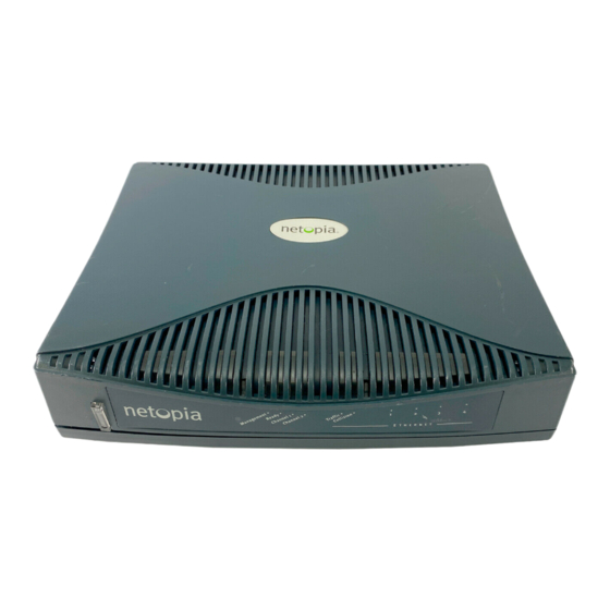
The Netopia R910 Ethernet Router is a stand-alone, multiprotocol broadband router for connecting diverse local area networks (LANs) to the Internet and other remote networks. Combining the Netopia R910 with a cable or DSL modem provides businesses with a low-cost connection to the Internet while retaining the power of a router. -
Page 10: How To Use This Guide
How to use this guide This guide is designed to be your single source for information about your Netopia R910 Ethernet Router. It is intended to be viewed on-line, using the powerful features of the Adobe Acrobat Reader. The information display has been deliberately designed to present the maximum information in the minimum space on your screen. -
Page 11: Chapter 2 - Setting Up Internet Services
Using NAT and MultiNAT features, you can configure your Netopia router to give all computers, printers, and other IP hosts access to the Internet using one or a limited number of IP addresses. This means that you have more flexibility in selecting ISP account types. The most affordable single IP account may be sufficient for your needs. -
Page 12: Local Lan Ip Address Information To Obtain
If you are not using NAT, you should obtain: The Ethernet IP address for your Netopia R910 The Ethernet IP subnet mask for your Netopia R910 An IP address for each device on your network, in the same network range as the Netopia R910. -
Page 13: Chapter 3 - Making The Physical Connections
For small networks, install the Netopia R910 near one of the LANs. For large networks, you can install the Netopia R910 in a wiring closet or a central network administration site. In most cases the router will be near the cable or DSL modem which is near the cable or DSL wall outlet. You could pull a line from the wall outlet to a wiring closet if you store the modem and router there. -
Page 14: What You Need
You will need: A Windows 95, 98, 2000, or NT–based PC or a Macintosh computer with Ethernet connectivity for configuring the Netopia R910. This may be built-in Ethernet or an add-on card, with TCP/IP installed and configured. See “Hardware and operating system requirements” on page An Internet modem such as a cable modem or DSL bridge connected to the appropriate wall outlet for your Internet service source. -
Page 15: Netopia R910 Ethernet Router Back Panel Ports
4-port Ethernet hub Four Ethernet jacks. You will use one of these to configure the Netopia R910. For a new installation, use the Ethernet connection. Alternatively, you can use the console connection to run console-based management using a direct serial connection. -
Page 16: Netopia R910 Ethernet Router Status Lights
3-16 User’s Reference Guide Netopia R910 Ethernet Router status lights The figure below represents the Netopia R910 status light (LED) panel. Netopia R910 LED front panel The following table summarizes the meaning of the various LED states and colors: When this happens... -
Page 17: Chapter 4 - Connecting To Your Local Area Network
This chapter describes how to physically connect the Netopia R910 to your local area network (LAN). Before you proceed, make sure the Netopia R910 is properly configured. You can customize the router’s configuration for your particular LAN requirements using console-based management (see page 6-31). -
Page 18: Readying Computers On Your Local Network
4-18 User’s Reference Guide After Using the Netopia R910 Ethernet Router, you can connect multiple computers to the Internet with a single user account. using a DSL modem with a Netopia R910 using a cable modem with a Netopia R910 While this network model is typical, other network models are possible. - Page 19 TCP/IP stack: This is the software that lets your PC or Macintosh communicate using Internet protocols. TCP/IP stacks must be configured with some of the same information you used to configure the Netopia R910. There are a number of TCP/IP stacks available for PC computers. Windows 95 includes a built-in TCP/IP stack.
-
Page 20: Connecting To An Ethernet Network
You can connect 10Base-T networks to the Netopia R910. The following table displays some important attributes of these connections. 10Base-T You can connect a standard 10Base-T Ethernet network to the Netopia R910 using any of its available Ethernet ports. Netopia R910 Ethernet Router back panel... - Page 21 The Netopia R910 in a 10Base-T network Ethernet To connect your 10Base-T network to the Netopia R910 through an Ethernet port, use a 10Base-T cable with RJ-45 connectors. If you have more than four devices to connect, you can attach additional devices using a 10Base-T hub, using a cross-over cable.
- Page 22 4-22 User’s Reference Guide...
-
Page 23: Chapter 5 — Configuring Tcp/Ip
Be sure the computer you use to configure your Netopia R910 has TCP/IP software and hardware properly configured to work with a router and the network service provider you will be using. Typically, this means that you will have your computer set up to accept a dynamically assigned IP address from the router, although other options are possible. -
Page 24: Configuring Tcp/Ip On Windows 95 Or 98
5-24 User’s Reference Guide Configuring TCP/IP on Windows 95 or 98 Be sure TCP/IP is installed and configured on your Windows computer. The following is a quick guide to configuring TCP/IP for Windows machines. Configuring TCP/IP in a Windows machine requires the following: An Ethernet card (also known as a network adapter) The TCP/IP protocol must be “bound”... - Page 25 Click OK in this window, and the next window. When prompted, reboot the computer. Note: More details about Windows 95 TCP/IP configuration (including dial-up) can be found in Technote NIR_027, “Windows 95 TCP/IP Properties and the Netopia Router,” located on the Netopia Web site. Configuring TCP/IP 5-25...
-
Page 26: Configuring Tcp/Ip On A Macintosh Computer
Note: If you want to use the Dynamic Host Configuration Protocol (DHCP) server built into your Netopia R910 to assign IP addresses to your Macintoshes, you must be running Open Transport. You can have your Netopia R910 dynamically assign IP addresses using MacTCP; however, to do so requires that the optional AppleTalk kit be installed and this can only be done after the router is configured. - Page 27 Static configuration (optional) If you are manually configuring from a fixed or static IP address, then perform the following: Go to the Apple menu. Select Control Panels and then TCP/IP or MacTCP. With the TCP/IP window open, go to the Edit menu and select User Mode.
- Page 28 If you want to use MacIP to dynamically assign IP addresses to the Macintosh computers on your network you must install the optional AppleTalk feature set kit. Note: You cannot use MacIP dynamic configuration to configure your Netopia R910 Ethernet to Ethernet Router because you must first configure the router in order to enable AppleTalk.
- Page 29 These are the only fields you need to modify in these screens. Note: More information about configuring your Macintosh computer for TCP/IP connectivity through a Netopia R910 can be found in Technote NIR_026, “Open Transport and Netopia Routers,” located on the Netopia Web site.
- Page 30 5-30 User’s Reference Guide...
-
Page 31: Configuration
Console-based management is a menu-driven interface for the capabilities built in to the Netopia R910. Console-based management provides access to a wide variety of features that the router supports. You can customize these features for your individual setup. This chapter describes how to access the console-based management screens. -
Page 32: Connecting Through A Telnet Session
“Quick View status overview” on page 12-109 Connecting through a Telnet session Features of the Netopia R910 can be configured through the console screens. Before you can access the console screens through Telnet, you must have: A network connection locally to the router or IP access to the router. -
Page 33: Configuring Telnet Software
ZTerm, included on the Netopia CD, for Macintosh computers. The Netopia R910 back panel has a connector labeled “Console” for attaching the Router to either a PC or Macintosh computer via the serial port on the computer. (On a Macintosh computer, the serial port is called the Modem port or Printer port.) This connection lets you use the computer to configure and monitor the Netopia... -
Page 34: Navigating Through The Console Screens
The new baud rate is displayed at the bottom of the screen. Navigating through the console screens Use your keyboard to navigate the Netopia R910’s configuration screens, enter and edit information, and make choices. The following table lists the keys to use to navigate through the console screens. -
Page 35: Chapter 7 - Easy Setup
This chapter describes how to use the Easy Setup console screens on your Netopia R910 Ethernet Router. After completing the Easy Setup console screens, your router will be ready to connect to the Internet or another remote site. This chapter covers the following topics: “Easy Setup console screens”... - Page 36 If you do not see the Main Menu, verify that: The computer used to view the console screen has its serial port connected to the Netopia R910’s Console port or an Ethernet connection to one of its Ethernet ports. See your router”...
-
Page 37: Quick Easy Setup Connection Path
Quick Easy Setup connection path This section may be all you need to do to configure your Netopia R910 Ethernet Router to connect to the Internet. If your ISP supports DHCP Your Netopia R910 Ethernet Router comes preconfigured with the ability to accept an IP address dynamically assigned by your ISP. - Page 38 Return. When prompted, select CONTINUE, and press Return. The router will restart and your configuration settings will be activated. You can then Exit or Quit your Telnet application. For more Easy Setup options see Netopia R910 v4.8 Easy Setup... WAN Configuration... System Configuration...
-
Page 39: More Easy Setup Options
Set up the basic IP attributes of your Ethernet Module in this screen. WAN Ethernet Configuration The WAN Ethernet Configuration screen is where you configure the parameters that control the Netopia R910’s connection to a specific remote destination, usually your ISP or a corporate site. -
Page 40: Ip Easy Setup
7-40 User’s Reference Guide IP Easy Setup The IP Easy Setup screen is where you enter information about your Netopia Router’s: Ethernet IP address Ethernet Subnet mask Domain Name Domain Name Server IP address Default gateway IP address Whether to serve IP addresses or not Consult with your network administrator to obtain the information you will need. -
Page 41: Easy Setup Security Configuration
Note: If the Netopia R910’s WAN interface is acting as a DHCP client, do not change the default settings for Steps 3, 4, and 5. Select Primary Domain Name Server and enter the IP address your ISP has given you. An alternate or Secondary Domain Name Server field will appear, where you can enter a secondary DNS IP address if your... - Page 42 Note: You can also restart the system at any time by using the Restart System utility (see system” on page 14-166) or by turning the Netopia Router off and on with the power switch. Easy Setup is now complete. “Restarting the...
-
Page 43: Chapter 8 - Wan And System Configuration
Console-based management is a menu-driven interface for the capabilities built in to the Netopia R910. Console-based management provides access to a wide variety of features that the router supports. You can customize these features for your individual setup. This chapter describes how to access the console-based management screens. -
Page 44: System Configuration Screens
Netopia R910 will accept routing information provided by RIP packets from other routers that use different subnet masks. If you want the Netopia R910 to advertise its routing table to other routers via RIP, select Transmit RIP and select v1, v2 (broadcast), or v2 (multicast) from the popup menu. With Transmit RIP v1 selected, the Netopia R910 will generate RIP packets only to other RIP v1 routers. -
Page 45: Navigating Through The System Configuration Screens
Beginning in the Main Menu, select System Configuration and press Return. The System Configuration screen appears. Select IP Setup and press Return. The IP Setup screen appears. To go back in this sequence of screens, use the Escape key. Netopia R910 v4.8 Easy Setup... WAN Configuration... System Configuration... -
Page 46: System Configuration Features
8-46 User’s Reference Guide System configuration features The Netopia R910 Ethernet Router’s default settings may be all you need to configure your Netopia R910. Some users, however, require advanced settings or prefer manual control over the default selections. For these users, the Netopia R910 provides system configuration options. -
Page 47: Ip Setup
IP setup These screens allow you to configure your network’s use of IP. Details are given in Chapter 9, “IP Setup and Network Address Translation.” Filter sets (firewalls) These screens allow you to configure security on your network by means of filter sets and a basic firewall. Details are given in Chapter 13, “Security.”... -
Page 48: Console Configuration
These screens allow you to add users and define passwords on your network. Details are given in Chapter 13, “Security.” Upgrade feature set You can upgrade your Netopia R910 by adding new feature sets through the Upgrade Feature Set utility. Console Configuration 38400 CANCEL... -
Page 49: Logging
See the release notes that came with your router or feature set upgrade, or visit the Netopia Web site at www.netopia.com for information on new feature sets, how to obtain them, and how to install them on your Netopia R910. -
Page 50: Installing The Syslog Client
8-50 User’s Reference Guide Installing the Syslog client The Goodies folder on the Netopia CD contains a Syslog client daemon program that can be configured to report the WAN events you specified in the Logging Configuration screen. To install the Syslog client daemon, exit from the graphical Netopia CD program and locate the CD directory structure through your Windows desktop, or through Windows Explorer. -
Page 51: Chapter 9 - Ip Setup And Network Address Translation
The Netopia R910 uses Internet Protocol (IP) to communicate both locally and with remote networks. This chapter shows you how to configure the Router to route IP traffic. You also learn how to configure the router to serve IP addresses to hosts on your local network. - Page 52 *or corporate intranet router When NAT is enabled, the Netopia R910 can use either a statically assigned IP address or one dynamically assigned each time the router connects to the ISP. While a dynamically assigned IP address offers the ISP more flexibility, it does have an important limitation: the router requires a static IP address to support Web, FTP, or...
-
Page 53: Using Network Address Translation
Note: See “Associating port numbers with nodes” on page By default, Network Address Translation is enabled in the Netopia R910. If you disabled it and now want to reenable it: From the WAN Configuration menu in the Main Menu screen, select WAN (Wide Area Network) Setup. - Page 54 For more information see Appendix B, “Understanding IP Addressing” Netopia NAT Behavior” If your ISP uses numbered (interface-based) routing, select Local WAN IP Address and enter the local WAN address your ISP gave you. Then select Local WAN IP Mask and enter the WAN subnet mask of the remote site you will connect to.
-
Page 55: Associating Port Numbers With Nodes
Telnet uses port number 23 SNMP uses port number 161 To help direct incoming IP traffic to the appropriate server, the Netopia R910 lets you associate these and other port numbers with distinct IP addresses on your internal LAN using exported services. See page 9-56 for details. -
Page 56: Ip Setup
Main Menu The IP Setup options screen is where you configure the Ethernet side of the Netopia R910. The information you enter here controls how the router routes IP traffic. Consult your network administrator or Internet service provider to obtain the IP setup information (such as the Ethernet IP address, Ethernet subnet mask, default IP gateway and Primary Domain Name Server IP address) you will need before changing any of the settings in this screen. - Page 57 Set to “Both,” the Netopia R910 will accept information from either RIP v1 or v2 routers. If you want the Netopia R910 to advertise its routing table to other routers via RIP, select Transmit RIP and select v1, v2 (broadcast), or v2 (multicast) from the popup menu. With Transmit RIP v1 selected, the Netopia R910 will generate RIP packets only to other RIP v1 routers.
- Page 58 9-58 User’s Reference Guide Exports, Add Export, and Delete Export. Return/Enter to configure UDP/TCP Port-to-IP Address redirection. Select Add Export. The Add Exported Service screen appears. Service... Local Server's IP Address: ADD EXPORT NOW Exported Services (Local Port to IP Address Remapping) Show/Change Exports...
- Page 59 Select any of the services/ports and press Return to associate it with the address of a server on your local area network. For example, if we select www-http 80, press Return, and type 10.0.0.2, the Netopia R910 redirects any incoming traffic destined for a Web server to address 10.0.0.2.
-
Page 60: Ip Subnets
9-60 User’s Reference Guide Press Escape when you are finished configuring exported services. You are returned to the IP Setup screen. Ethernet IP Address: Ethernet Subnet Mask: Define Additional Subnets... Default IP Gateway: Primary Domain Name Server: Secondary Domain Name Server: Domain Name: Receive RIP: Transmit RIP:... - Page 61 All eight row labels are always visible, regardless of the number of subnets configured. To add an IP subnet, enter the Netopia R910’s IP address on the subnet in the IP Address field in a particular row and the subnet mask for the subnet in the Subnet Mask field in that row.
-
Page 62: Static Routes
Static routes are IP routes that are maintained manually. Each static route acts as a pointer that tells the Netopia R910 how to reach a particular network. However, static routes are used only if they appear in the IP routing table, which contains all of the routes used by the Netopia R910 (see page 12-115). - Page 63 The Static Routes screen will appear. Configure/View/Delete Static Routes from this and the following Screens. Viewing static routes To display a view-only table of static routes, select Display/Change Static Route. The table shown below will appear. +-Dest. Network---Subnet Mask-----Next Gateway----Priority-Enabled-+ +------------------------------------------------------------------+ | 0.0.0.0 +------------------------------------------------------------------+...
- Page 64 Select Destination Network Subnet Mask and enter the subnet mask used by the destination network. Select Next Gateway IP Address and enter the IP address for the router that the Netopia R910 will use to reach the destination network. This router does not necessarily have to be part of the destination network, but it must at least know where to forward packets destined for that network.
- Page 65 Rules of static route installation The Netopia R910 applies certain rules before installing enabled static routes in the IP routing table. An enabled static route will not be installed in the IP routing table if any of the following conditions are true: The static route’s Next Gateway IP Address matches the IP address used by the Netopia R910’s Ethernet...
-
Page 66: Ip Address Serving
Menu Configuration In addition to being a router, the Netopia R910 is also an IP address server. There are three protocols it can use to distribute IP addresses. The first, called Dynamic Host Configuration Protocol (DHCP), is widely supported on PC networks, as well as Apple Macintosh computers using Open Transport and computers using the UNIX operating system. - Page 67 AppleTalk kit installed) are automatically enabled. Select Number of Client IP Addresses and enter the total number of contiguous IP addresses that the Netopia R910 will distribute to the client machines on your local area network. 12-user models are limited to twelve IP addresses.
-
Page 68: Ip Address Pools
The value defaults to the Netopia R910’s IP address on the corresponding subnet (or the Netopia R910’s default gateway, if that gateway is located on the subnet in question). You can override the value by entering any address that is part of the subnet. - Page 69 When requesting an address, a client may provide a client identifier, or, if it does not, the Netopia R910 may construct a pseudo-client identifier for the client. When the client subsequently requests an address, the Netopia R910 will attempt to serve the address previously associated with the client identifier.
-
Page 70: Dhcp Netbios Options
9-70 User’s Reference Guide DHCP NetBIOS Options If your network uses NetBIOS, you can enable the Netopia R910 to use DHCP to distribute NetBIOS information. NetBIOS stands for Network Basic Input/Output System. It is a layer of software originally developed by IBM and Sytek to link a network operating system with specific hardware. - Page 71 From the NetBios Type pop-up menu, select the type of NetBIOS used on your network. Serve NetBios Type: NetBios Type... Serve NetBios Scope: NetBios Scope: Serve NetBios Name Server: NetBios Name Server IP Addr: To serve DHCP clients with the NetBIOS scope, select Serve NetBios Scope and toggle it to Yes. Select NetBios Scope and enter the scope.
- Page 72 9-72 User’s Reference Guide Reset All Leases Release BootP Leases Reclaim Declined Addresses Hit RETURN/ENTER, you will return to the previous screen. Select Release BootP Leases and press Return. You have finished your IP setup. IP Address Lease Management...
-
Page 73: About Pptp Tunnels
(Internet). The Netopia Router can be used in VPNs either to initiate the connection or to answer it. When used in this way, the routers are said to be tunnelling through the public network (Internet). The advantages are that, like your long distance phone call, you don't need a direct line between one computer or LAN and the other, but use the local connections, making it much cheaper;... - Page 74 Netopia’s PPTP implementation is compatible with Microsoft’s and can function as either the client (PAC) or the server (PNS). As a client, a Netopia R-series router can provide all users on a LAN with secure access over the Internet to the resources of another LAN by setting up a tunnel with a Windows NT server running Remote Access Services (RAS) or with another Netopia Router.
-
Page 75: About Ipsec Tunnels
PPTP language), or a foreign agent (in ATMP language). When used to answer the tunnelled connection, the Netopia Router is called a PPTP Network Server (PNS, in PPTP language) or a home agent (in ATMP language). In either case, the Netopia Router wraps, or encapsulates, information that one end of the tunnel exchanges with the other, in a wrapper called General Routing Encapsulation (GRE), at one end of the tunnel, and unwraps, or decapsulates, it at the other end. - Page 76 Note: The Netopia R910 Router has access to Connection Profiles for tunnelling purposes. If the PPP dialup kit is not installed, you cannot use PPP as a datalink encapsulation, and you will have access only to ATMP and PPTP.
-
Page 77: Ip Profile Parameters
When you define a Connection Profile as using PPTP by selecting PPTP as the datalink encapsulation method, and then select Data Link Options, the PPTP Tunnel Options screen appears. PPTP Partner IP Address: Tunnel Via Gateway: Data Compression... Authentication... Send Host name: Send Secret: Receive Host name: Receive Secret:... - Page 78 MS-CHAP version 1 (MS-CHAP-V1). When you choose MS-CHAP as the authentication method for the PPTP tunnel, the Netopia router will start negotiating MS-CHAP-V2. If the router you are connecting to does not support MS-CHAP-V2, it will fall back to MS-CHAP-V1, or, if the router you are connecting to does not support MPPE at all, the PPP session will be dropped.
- Page 79 Netopia’s ATMP implementation supports Data Encryption Standard (DES) data encryption for user data transfer over the ATMP tunnel between two Netopia routers. The encryption option, None or DES, is a selectable option in the ATMP Tunnel Options screen.
-
Page 80: About Ipsec Tunnels
firmware. This means that, worldwide, the Netopia R910 Router, because it supports VPN, also supports 128-bit encryption for free, when using PPTP tunnels. ATMP does not have an option of using 128-bit MPPE. If you are using ATMP between two Netopia routers you can optionally set 56-bit DES encryption. - Page 81 The Add Connection Profile screen appears. Profile Name: Profile Enabled: Data Link Encapsulation... IP Enabled: IP Profile Parameters... Interface Group... COMMIT From the Data Link Encapsulation pop-up menu select IPsec. Then select Data Link Options. The IPsec Encryption & Authentication Options screen appears. Encryption Transform...
- Page 82 10-82 User’s Reference Guide Encryption Transform... Encryption Key 1: Encryption Key 2: Encryption Key 3: Authentication Type... Authentication Transform... Authentication Key: Compression Type... COMMIT You must enter an Encryption Key or keys if the Encryption Transform is DES. The key must be a hexadecimal entry of eight bytes (16 bytes of input).
-
Page 83: Advanced Ip Profile Options
The following IP Profile Options screen is displayed for an IPsec Connection Profile. SPI (Security Parameters Index): Remote Tunnel Endpoint Address: Remote Members Network: Remote Members Mask: Address Translation Enabled: NAT Map List... NAT Server List... PAT IP Address: Filter Set... Remove Filter Set Advanced IP Profile Options... - Page 84 10-84 User’s Reference Guide following section). Note: The SPI title field above changes to SPI (Security Parameters Index) -- Use Advanced IP Profile Options if any of the SPI values differ from each other. ESP Receive SPI: ESP Transmit SPI: AH Receive SPI: AH Transmit SPI: Local Tunnel Endpoint Address:...
-
Page 85: Vpn Default Answer Profile
The WAN Configuration menu offers a VPN Default Answer Profile option. Use this selection when your router is acting as the server for VPN connections, that is, when you are on the answering end of the tunnel establishment. The VPN Default Answer Profile determines the way the attempted tunnel connection is answered. -
Page 86: Vpn Quickview
10-86 User’s Reference Guide For PPTP tunnel connections only, you must define what type of authentication these connections will use. Select Receive Authentication and press Return. A pop-up menu offers the following options: PAP (the default), CHAP, or MS-CHAP. If you chose PAP or CHAP authentication, from the Data Compression pop-up menu select either None (the default) or Standard LZS. - Page 87 Virtual Private Networks (VPN) 10-87 Profile Name: Lists the name of the Connection Profile being used, if any. Type: Shows the data link encapsulation method (PPTP or ATMP). Rx Pckts: Shows the number of packets received via the VPN tunnel. Tx Pckts: Shows the number of packets transmitted via the VPN tunnel.
- Page 88 Microsoft Windows Dial-Up Networking software permits a remote standalone workstation to establish a VPN tunnel to a PPTP server such as a Netopia Router located at a central site. Dial-Up Networking also allows a mobile user who may not be connected to a PAC to dial into an intermediate ISP and establish a VPN tunnel to, for example, a corporate headquarters, remotely.
- Page 89 The Communications window appears. In the Communications window, select Dial-Up Networking and click the OK button. This returns you to the Windows Setup screen. Click the OK button. Respond to the prompts to install Dial-Up Networking from the system disks or CD-ROM. When prompted, reboot your PC.
- Page 90 Windows 98 users select PPP: Windows 98, Windows NT Server, Internet In the Allowed network protocols area check TCP/IP and uncheck all of the other checkboxes. Note: Netopia’s PPTP implementation does not currently support tunnelling of IPX and NetBEUI protocols.
- Page 91 Click the TCP/IP Settings button. If your ISP uses dynamic IP addressing (DHCP), select the Server assigned IP address radio button. If your ISP uses static IP addressing, select the Specify an IP address radio button and enter your assigned IP address in the fields provided. Also enter the IP address in the Primary and Secondary DNS fields.
-
Page 92: Installing The Vpn Client
10-92 User’s Reference Guide Before installing the VPN Client you must have TCP/IP installed and have an established Internet connection. From your Internet browser navigate to the following URL: http://www.microsoft.com/NTServer/nts/downloads/recommended/dunl3win95/releasenotes.aso Download the Microsoft Windows 95 VPN patch dun 1.3 to the Windows 95 computer you intend to use as a VPN client with PPTP. - Page 93 Click the Windows Setup tab. The Windows Setup screen will be displayed within the top center box. Double-click Communications. This displays a list of possible selections for the communications option. Active components will have a check in the checkboxes to their left. Check Dial Up Networking at the top of the list and Virtual Private Networking at the bottom of the list.
- Page 94 Note: The Netopia R910 Router has access to Connection Profiles for tunnelling purposes. If the PPP dialup kit is not installed, you cannot use PPP as a datalink encapsulation, and have access only to ATMP and PPTP. If the kit is installed you also have access to PPP.
- Page 95 Profile Name: Profile Enabled: Data Link Encapsulation... Data Link Options... IP Enabled: IP Profile Parameters... COMMIT When you define a Connection Profile as using ATMP by selecting ATMP as the datalink encapsulation method, and then select Data Link Options, the ATMP Tunnel Options screen appears. ATMP Partner IP Address: Tunnel Via Gateway: Network Name:...
- Page 96 You can specify a Network Name. When the tunnel partner is another Netopia router, this name may be used to match against a Connection Profile. When the partner is an Ascend router in Gateway mode, then Network Name is used by the Ascend router to match a gateway profile.
- Page 97 Ordinarily, Ping is an excellent troubleshooting tool, but it will not be effective in this circumstance. Instead, use another TCP- or UDP-based network service for troubleshooting. Since the Netopia Router is capable of serving Telnet and HTTP, we recommend using these services instead of Ping.
-
Page 98: Pptp Example
10-98 User’s Reference Guide An administrator interested in securing a network will usually combine the use of VPNs with the use of a firewall or some similar mechanism. This is because a VPN is not a complete security solution, but rather a component of overall security. -
Page 99: Chapter 10 — Virtual Private Networks (Vpn)
To enable a firewall to allow PPTP traffic, you must provision the firewall to allow inbound and outbound TCP packets specifically destined for port 1723. The source port may be dynamic, so often it is not useful to apply a compare function upon this portion of the control/negotiation packets. You must also set the firewall to allow inbound and outbound GRE packets, enabling transport of the tunnel payload. - Page 100 10-100 User’s Reference Guide For Input Filter 2 set the Protocol Type to allow GRE as shown below. Enabled: Forward: Source IP Address: Source IP Address Mask: Dest. IP Address: Dest. IP Address Mask: Protocol Type: In the Display/Change IP Filter Set screen select Display/Change Output Filter. Display/Change Output Filter screen +-#----Source IP Addr----Dest IP Addr------Proto-Src.Port-D.Port--On?-Fwd-+ +-------------------------------------------------------------------------+...
- Page 101 For Output Filter 2 set the Protocol Type to allow GRE as shown below. Enabled: Forward: Source IP Address: Source IP Address Mask: Dest. IP Address: Dest. IP Address Mask: Protocol Type: Virtual Private Networks (VPN) 10-101 Change Output Filter 2 0.0.0.0 0.0.0.0 0.0.0.0...
- Page 102 10-102 User’s Reference Guide To enable a firewall to allow ATMP traffic, you must provision the firewall to allow inbound and outbound UDP packets specifically destined for port 5150. The source port may be dynamic, so often it is not useful to apply a compare function on this portion of the control/negotiation packets.
- Page 103 For Input Filter 2 set the Protocol Type to allow GRE as shown below. Enabled: Forward: Source IP Address: Source IP Address Mask: Dest. IP Address: Dest. IP Address Mask: Protocol Type: In the Display/Change IP Filter Set screen select Display/Change Output Filter. Display/Change Output Filter screen +-#----Source IP Addr----Dest IP Addr------Proto-Src.Port-D.Port--On?-Fwd-+ +-------------------------------------------------------------------------+...
- Page 104 10-104 User’s Reference Guide For Output Filter 2 set the Protocol Type to allow GRE as shown below. Enabled: Forward: Source IP Address: Source IP Address Mask: Dest. IP Address: Dest. IP Address Mask: Protocol Type: Change Output Filter 2 0.0.0.0 0.0.0.0 0.0.0.0...
- Page 105 DSL or cable modem. Some ISPs require user name and password authentication to connect you with their DSL or cable service. PPPoE allows user name and password authentication to the ISP via your R910’s Ethernet interface to your DSL or cable modem.
- Page 106 11-106 User’s Reference Guide Profile Name: Profile Enabled: Data Link Encapsulation... Data Link Options... IP Enabled: IP Profile Parameters... Interface Group... COMMIT Configure a new Conn. Profile. Finished? From the Data Link Encapsulation pop-up menu, select PPP. Select Data Link Options and press Return. The Datalink (PPP/MP) Options screen appears.
- Page 107 The Netopia R910 allows a central site router to supply an entire IP subnet, rather than a single IP address, for use by a Netopia router. If the applicable Connection Profile specifies an unnumbered, non-NAT connection and Negotiate LAN IP Addr/Mask is set to On, PPP will attempt to negotiate both an IP Address and subnet mask.
- Page 108 11-108 User’s Reference Guide The Quick View screen (as shown below) displays both Primary and Secondary DNS Server addresses. This is useful because both may be served via PPP. Default IP Gateway: Primary DNS Server: Secondary DNS Server: 163.176.4.10 ----------------MAC Address--------IP Address--------------------------------- Ethernet Hub: 00-00-c5-78-5d-10 Ethernet WAN1:...
-
Page 109: Chapter 12 — Monitoring Tools
“SNMP” on page 12-118 Quick View status overview You can get a useful, overall status report from the Netopia R910 in the Quick View screen. To go to the Quick View screen, select Quick View in the Main Menu. The Quick View screen has three status sections:... -
Page 110: General Status
IP Address: The Netopia R910’s IP address, entered in the IP Setup screen. Status lights This section shows the current real-time status of the Netopia R910’s status lights (LEDs). It is useful for remotely monitoring the router’s status. The Quick View screen’s arrangement of LEDs corresponds to the physical arrangement of LEDs on the router. -
Page 111: Statistics & Logs
The section “Netopia R910 Ethernet Router status lights” on page 3-16 for each LED. Note: Although the Quick VIew LED Status section lists the Channel 2 (CH2) LED, it is not used on the R910. Statistics & Logs Main Menu When you are troubleshooting your Netopia R910, the Statistics &... -
Page 112: Event Histories
You can view two different event histories: one for the router’s system and one for the WAN. The Netopia R910’s built-in battery backup prevents loss of event history from a shutdown or reset. - Page 113 WAN Event History The WAN Event History screen lists a total of 128 events on the WAN. The most recent events appear at the top. -Date-----Time-----Event------------------------------------------------------ ----------------------------------SCROLL UP----------------------------------- 08/11/98 12:15:54 --Device restarted----------------------------------------- 08/11/98 12:11:12 --Device restarted----------------------------------------- 08/11/98 10:36:38 08/11/98 10:36:38 --Device restarted----------------------------------------- ---------------------------------SCROLL DOWN---------------------------------- Clear History...
-
Page 114: Routing Tables
To clear the Device Event History, select Clear History and press Return. Routing tables You can view all of the IP routes in the Netopia R910’s IP routing table. To go to a routing table screen, select the IP routing table from the Statistics & Logs screen. - Page 115 IP routing table In the Statistics & Logs screen, select IP Routing Table and press Return. The IP routing table displays all of the IP routes currently known to the Netopia R910. Network Address-Subnet Mask-----via Router------Port------------------Type---- ----------------------------------SCROLL UP----------------------------------- 0.0.0.0 255.0.0.0 127.0.0.1...
-
Page 116: Served Ip Addresses
12-116 User’s Reference Guide Served IP Addresses You can view all of the IP addresses currently being served by the Netopia R910 Ethernet Router from the Served IP Addresses screen. From the Statistics & Logs menu, select Served IP Addresses. The Served IP Addresses screen appears. -
Page 117: System Information
System Information The System Information screen gives a summary view of the general system level values in the Netopia R910 Ethernet Router. From the Statistics & Logs menu select System Information. The System Information screen appears. -
Page 118: The Snmp Setup Screen
Ethernet MIB (RFC 1643) Netopia MIB These MIBs are on the Netopia R910 CD included with the Netopia R910. Load these MIBs into your SNMP management software in the order they are listed here. Follow the instructions included with your SNMP manager on how to load MIBs. -
Page 119: Snmp Traps
SNMP traps An SNMP trap is an informational message sent from an SNMP agent (in this case, the Netopia R910) to a manager. When a manager receives a trap, it may log the trap as well as generate an alert message of its own. - Page 120 The Netopia R910 sends traps using UDP (for IP networks). You can specify which SNMP managers are sent the IP traps generated by the Netopia R910. Up to eight receivers can be set. You can also review and remove IP traps.
- Page 121 Select an IP trap receiver from the table and press Return. In the Change IP Trap Receiver screen, edit the information as needed and press Return. Deleting IP trap receivers To delete an IP trap receiver, select Delete IP Trap Receiver in the IP Trap Receivers screen. Select an IP trap receiver from the table and press Return.
- Page 122 12-122 User’s Reference Guide...
-
Page 123: Suggested Security Measures
User accounts When you first set up and configure the Netopia R910, no passwords are required to access the configuration screens. Anyone could tamper with the router’s configuration by simply connecting it to a console. However, by adding user accounts, you can protect the most sensitive screens from unauthorized access. User accounts are composed of name/password combinations that can be given to authorized users. - Page 124 13-124 User’s Reference Guide Once user accounts are created, users who attempt to access protected screens will be challenged. Users who enter an incorrect name or password are returned to a screen requesting a name/password combination to access the Main Menu. To set up user accounts, in the System Configuration screen select Security and press Return.
-
Page 125: Telnet Access
Return to delete it. To exit the list without deleting the selected account, press Escape. Telnet access Telnet is a TCP/IP service that allows remote terminals to access hosts on an IP network. The Netopia R910 supports Telnet access to its configuration screens. -
Page 126: What's A Filter And What's A Filter Set?
filters to control network communications can greatly improve your network’s security. The Netopia R910’s packet filters are designed to provide security for the Internet connections made to and from your network. You can customize the router’s filter sets for a variety of packet filtering applications. - Page 127 Each inspector has a specific task. One inspector’s task may be to examine the destination address of all outgoing packages. That inspector looks for a certain destination—which could be as specific as a street address or as broad as an entire country—and checks each package’s destination address to see if it matches that destination.
-
Page 128: How Individual Filters Work
This rule applies to Telnet packets that come from a host with the IP address 199.211.211.17. If a match occurs, the packet is blocked. Here is what this rule looks like when implemented as a filter on the Netopia R910: +-#--Source IP Addr--Dest IP Addr-----Proto-Src.Port-D.Port--On?-Fwd-+ +--------------------------------------------------------------------+ 199.211.211.17... - Page 129 Parts of a filter A filter consists of criteria based on packet attributes. A typical filter can match a packet on any one of the following attributes: The source IP address (where the packet was sent from) The destination IP address (where the packet is going) The type of higher-layer Internet protocol the packet is carrying, such as TCP or UDP Port numbers A filter can also match a packet’s port number attributes, but only if the filter’s protocol type is set to TCP or...
- Page 130 13-130 User’s Reference Guide Less Than: For the filter to match, the packet’s port number must be less than the port number specified in the filter. Less Than or Equal: For the filter to match, the packet’s port number must be less than or equal to the port number specified in the filter.
- Page 131 Proto: The protocol to match. This can be entered as a number (see the table below) or as TCP or UDP if those protocols are used. Protocol ICMP Src. Port: The source port to match. This is the port on the sending host that originated the packet. D.
-
Page 132: Design Guidelines
13-132 User’s Reference Guide The filter should be enabled and instructed to block the Telnet packets containing the source address shown in step 2: On? = Yes Fwd = No This four-step process is how we produced the following filter from the original rule: +-#---Source IP Addr---Dest IP Addr-----Proto-Src.Port-D.Port--On?-Fwd-+ +----------------------------------------------------------------------+ 192.211.211.17... -
Page 133: Working With Ip Filters And Filter Sets
Discarded if all the filters are configured to pass (forward) Discarded if the set contains a combination of pass and discard filters Disadvantages of filters Although using filter sets can greatly enhance network security, there are disadvantages: Filters are complex. Combining them in filter sets introduces subtle interactions, increasing the likelihood of implementation errors. -
Page 134: Adding A Filter Set
13-134 User’s Reference Guide Return/Enter to configure and add a new Filter Set Set Up IP Filter Sets (Firewalls) from this and the following Menus. The procedure for creating and maintaining filter sets is as follows: Add a new filter set. Create the filters for the new filter set. - Page 135 Filter Set Name: Display/Change Input Filter... Add Input Filter... Delete Input Filter... Display/Change Output Filter... Add Output Filter... Delete Output Filter... ADD FILTER SET Configure the Filter Set name and its associated Filters. Naming a new filter set All new filter sets have a default name. The first filter set you add will be called Filter Set 1, the next filter will be Filter Set 2, and so on.
- Page 136 The Netopia R910 Router Packets in the Netopia R910 pass through an input filter if they originate in the WAN and through an output filter if they’re being sent out to the WAN. The process for adding input and output filters is exactly the same. The main difference between the two involves their reference to source and destination.
- Page 137 Enter the IP specific information for this filter. To make the filter active in the filter set, select Enabled and toggle it to Yes. If Enabled is toggled to No, the filter can still exist in the filter set, but it will have no effect. If you want the filter to forward packets that match its criteria to the destination IP address, select Forward and toggle it to Yes.
-
Page 138: Viewing Filter Sets
13-138 User’s Reference Guide 10. When you are finished configuring the filter, select ADD THIS FILTER NOW to save the filter in the filter set. Select CANCEL to discard the filter and return to the Add IP Filter Set screen. Viewing filters To display a view-only table of input (output) filters, select Display/Change Input Filter or Display/Change Output Filter in the Add IP Filter Set screen. -
Page 139: Modifying Filter Sets
filter set. A sample IP filter set This section contains the settings for a filter set called Basic Firewall, which is part of the Netopia R910’s factory configuration. Basic Firewall blocks undesirable traffic originating from the WAN (in most cases, the Internet), but passes all traffic originating from the LAN. - Page 140 13-140 User’s Reference Guide The five input filters and one output filter that make up Basic Firewall are shown in the table below. Input filter Setting Enabled Forward Source IP 0.0.0.0 address Source IP 0.0.0.0 address mask Dest. IP 0.0.0.0 address Dest.
- Page 141 Basic Firewall is suitable for a LAN containing only client hosts that want to access servers on the WAN, but not for a LAN containing servers providing services to clients on the WAN. Basic Firewall’s general strategy is to explicitly pass WAN-originated TCP and UDP traffic to ports greater than 1023. Ports lower than 1024 are the service origination ports for various Internet services such as FTP, Telnet, and the World Wide Web (WWW).
- Page 142 AURP tunnel. To allow an AURP tunnel between a remote AURP router with the IP address a.b.c.d (corresponding to a numbered IP address such as 163.176.8.243) and a local AURP router (including the Netopia R910 itself), insert the following input filter ahead of the current input filter 1: Enabled: Yes Forward: Yes Source IP Address: a.b.c.d...
-
Page 143: General Firewall Terms
Firewall tutorial General firewall terms Filter rule: A filter set is comprised of individual filter rules. Filter set: A grouping of individual filter rules. Firewall: A component or set of components that restrict access between a protected network and the Internet, or between two networks. -
Page 144: Firewall Design Rules
13-144 User’s Reference Guide Example TCP/UDP Ports TCP Port 20/21 Firewall design rules There are two basic rules to firewall design: “What is not explicitly allowed is denied.” “What is not explicitly denied is allowed.” The first rule is far more secure, and is the best approach to firewall design. It is far easier (and more secure) to allow in or out only certain services and deny anything else. - Page 145 and a packet goes through these rules destined for FTP, the packet would pass through the first filter rule (WWW), match the second rule (FTP), and the packet is allowed through. Even though the next rule is to deny all FTP traffic, the FTP packet will never make it to this rule.
-
Page 146: Filter Basics
In the source or destination IP address fields, the IP address that is entered must be the network address of the subnet. A host address can be entered, but the applied subnet mask must be 32 bits (255.255.255.255). The Netopia R910 has the ability to compare source and destination TCP or UDP ports. These options are as follows:... -
Page 147: Example Filters
Any port less than or equal to the port defined Matches only the port defined Matches the port or any port greater Matches anything greater than the port defined Incoming Packet Filter Netopia 200.1.1.0 (Source IP Network Address) 255.255.255.128 (Source IP Mask) Forward = No... - Page 148 This incoming IP packet (10000000) has a source IP address that does not match the network address in the Source IP Address field (00000000) in the Netopia R910. This rule will forward this packet because the packet does not match.
- Page 149 Since the Source IP Network Address in the Netopia R910 is 01100000, and the source IP address after the logical AND is 1011000, this rule does not match and this packet will be passed. Example 4 Filter Rule: Incoming packet has the source address of 200.1.1.104.
- Page 150 13-150 User’s Reference Guide Since the Source IP Network Address in the Netopia R910 is 01100000, and the source IP address after the logical AND is 01100000, this rule does match and this packet will NOT be passed. This rule masks off a...
- Page 151 TheNetopia R910 implements a Remote Authentication Dial-In User Service (RADIUS) client (RFC 2138) and adds the ability to authenticate console configuration access using a RADIUS server. This feature is strictly for console menu access authentication only, and is not intended for WAN connectivity access authentication.
- Page 152 13-152 User’s Reference Guide If you select Advanced Security Options and press Return, the Advanced Security Options screen appears. Security Databases... RADIUS Server Addr/Name: RADIUS Server Secret: Alt RADIUS Server Addr/Name: Alt RADIUS Server Secret: RADIUS Identifer: RADIUS Server Authentication Port: 1812 You select your desired mode by using the Security Databases…...
- Page 153 hostname to be resolved using the Domain Name System (DNS) information configured in the router, or by using an IP address in dotted-quad notation. The RADIUS Server Addr/Name items are limited to 63 characters. In addition to specifying the server’s hostname or IP address, you must also specify a RADIUS Server Secret and an Alt RADIUS Server Secret (if configured) known to both the router and the RADIUS server.
- Page 154 | continue you will be unable to configure this device unless | | a Radius Server is available to authenticate you. +-------------------------------------------------------------+ Show Users... Add User... Delete User... Advanced Security Optio| Password for This Scree+-------------+): Security Options CONTINUE +-------------+ +-------------+ | Netopia URG | | tonyf CANCEL...
-
Page 155: Chapter 14 — Utilities And Diagnostics
A number of utilities and tests are available for system diagnostic and control purposes. This section covers the following topics: “Ping” on page 14-156 “Trace Route” on page 14-158 “Telnet client” on page 14-159 “Disconnect Telnet console session” on page 14-160 “Factory defaults”... -
Page 156: Ping
(Ping-capable) IP host. Each time the target host receives a Ping packet, it returns a packet to the original sender. Ping allows you to see whether a particular IP destination is reachable from the Netopia R910. You can also ascertain the quality and reliability of the connection to the desired destination by studying the Ping test’s statistics. - Page 157 Ping packets. Note that the second return Ping packet is considered to be late because it is not received by the Netopia R910 before the third Ping packet is sent. The first and third return Ping packets are on time.
-
Page 158: Trace Route
The time-to-live (TTL) value for each Ping packet sent by the Netopia R910 is 255, the maximum allowed. The TTL value defines the number of IP routers that the packet can traverse. Ping packets that reach their TTL value are dropped, and a “destination unreachable”... -
Page 159: Telnet Client
Select Use Reverse DNS to learn the names of the routers between the Netopia Router and the destination router. The default is Yes. Select START TRACE ROUTE and press Return. A scrolling screen will appear that lists the destination, number of hops, IP addresses of each hop, and DNS names, if selected. -
Page 160: Disconnect Telnet Console Session
Trivial File Transfer Protocol (TFTP) is a method of transferring data over an IP network. TFTP is a client-server application, with the router as the client. To use the Netopia R910 as a TFTP client, a TFTP server must be available. -
Page 161: Updating Firmware
WAN module firmware governs how the WAN module communicates with the remote site. WAN module firmware is included on your Netopia CD for XMODEM transfer and later updates will be available on the Netopia website. Router firmware updates are also periodically posted on the Netopia website. -
Page 162: Downloading Configuration Files
Some models do not support all firmware versions. Loading an incorrect firmware version can permanently damage the unit. Do not manually power down or reset the Netopia R910 while it is automatically resetting or it could be damaged. If you choose to download the firmware, the TFTP Transfer State item will change from Idle to Reading Firmware. -
Page 163: Uploading Configuration Files
Using TFTP, you can send a file containing a snapshot of the router’s current configuration to a TFTP server. The file can then be downloaded by a different Netopia R910 unit to configure its parameters (see configuration files” on page 14-162). -
Page 164: Updating Firmware
Send Firmware to Netopia WAN module... WAN module Firmware Status: Updating firmware Firmware updates may be available periodically from Netopia or from a site maintained by your organization’s network administration. The procedure below applies whether you are using the console or the WAN interface module. -
Page 165: Downloading Configuration Files
The system will reset at the end of a successful file transfer to put the new firmware into effect. While the system resets, the LEDs will blink on and off. Caution! Do not manually power down or reset the Netopia R910 while it is automatically resetting or it could be damaged. Downloading configuration files The Netopia R910 can be configured by downloading a configuration file. -
Page 166: Restarting The System
You can restart the system by selecting the Restart System item in the Utilities & Diagnostics screen. You must restart the system whenever you reconfigure the Netopia R910 and want the new parameter values to take effect. Under certain circumstances, restarting the system may also clear up system or network malfunctions. -
Page 167: Configuration Problems
Note: If you are attempting to modify the IP address or subnet mask from a previous, successful configuration attempt, you will need to clear the IP address or reset your Netopia R910 to the factory default before reinitiating the configuration process. For further information on resetting your Netopia R910 to factory default, “Factory defaults”... -
Page 168: Console Connection Problems
Problems communicating with remote IP hosts Verify the accuracy of the default gateway’s IP address (entered in the IP Setup or Easy Setup screen). Use the Netopia R910’s Ping utility, in the Utilities & Diagnostics screen, and try to ping local and remote hosts. See “Ping”... -
Page 169: How To Reset The Router To Factory Defaults
Power outages If you suspect that power was restored after a power outage and the Netopia R910 is connected to a remote site, you may need to switch the Netopia R910 off and then back on again. After temporary power outages, a connection that still seems to be up may actually be disconnected. -
Page 170: Technical Support
If you contact us by telephone, please be ready to supply Netopia Technical Support with the information you used to configure the Netopia R910. Also, please be at the site of the problem and prepared to reproduce it and to try some troubleshooting steps. - Page 171 Online product information Product information can be found in the following: Netopia World Wide Web server via http://www.netopia.com Internet via anonymous FTP to ftp.netopia.com/pub Online Technical Support Technical notes and Frequently Asked Questions which answer the most commonly asked questions and offer solutions for many common problems are available 24 hours a day on our Company Web site at http://www.netopia.com/support/.
- Page 172 A-172 User’s Reference Guide...
-
Page 173: What I Ip?"
This appendix is a brief general introduction to IP addressing. A basic understanding of IP will help you in configuring the Netopia R910 and using some of its powerful features, such as static routes and packet filtering. In packets, a header is part of the envelope information that surrounds the actual data being transmitted. In e-mail, a header is usually the address and routing information found at the top of messages. -
Page 174: Subnets And Subnet Masks
B-174 User’s Reference Guide IP addresses indicate both the identity of the network and the identity of the individual host on the network. The number of bits used for the network number and the number of bits used for the host number can vary, as long as certain rules are followed. -
Page 175: Example: Using Subnets On A Class C Ip Internet
When setting up IP routing with a Class A Address, or even with multiple Class C Addresses, subnetting is fairly straightforward. Subnetting a single Class C address between two networks, however, is more complex. This section describes the general procedures for subnetting a single Class C network between two Netopia routers so that each can have Internet access. - Page 176 Below is a diagram of a simple network configuration. The ISP is providing a Class C address to the customer site, and both networks A and B want to gain Internet access through this address. Netopia R910 B connects to Netopia R910 A and is provided Internet access through Routers A and B.
-
Page 177: Example: Working With A Class C Subnet
ISP's equipment. The most important item in this configuration is the static route defined on Router B. This tells Router B what path to take to get to the network defined by Netopia R910 B. Without this information, Customer Site B will be able to access Customer Site A, but not the Internet. -
Page 178: Technical Note On Subnet Masking
These two methods are not mutually exclusive; you can manually issue some of the addresses while the rest are distributed by the Netopia R910. Using the router in this way allows it to function as an address server. One reason to use the Netopia R910 as an address server is that it takes less time than manually distributing the addresses. -
Page 179: Configuration
DHCP address lease for one hour. The number of devices a Netopia R910 can serve DHCP to is 512. This is imposed by global limits on the size of the address serving database, which is shared by all address serving functions active in the router. -
Page 180: Tips And Rules For Distributing Ip Addresses
Once the Mac workstation requests and receives a valid address, the Netopia R910 actively checks for the workstation’s existence once every minute. For a dynamic address, the Netopia R910 releases the address back to the address pool after it has lost contact with the Mac workstation for over 2 minutes. - Page 181 See below for a further explanation and an example. The network address issued by an ISP cannot be used as a host address. Understanding IP Addressing B-181 Distributed to the (Ethernet IP address) Pool of addresses distributed Netopia R910 Manually distributed (static) by MacIP and DHCP...
-
Page 182: Nested Ip Subnets
The figure at left shows a possible network configuration following this scheme. The main network is set up with the Class C address a.b.c.0, and contains Router A (which could be a Netopia R910), a Netopia R910, and a number of other hosts. Router A maintains a link to the Internet, and can be used as the default gateway. - Page 183 For Router C The Netopia R910’s connection profiles for Routers B and C create entries in its IP routing table. One entry points to the subnet a.b.c.128, while a second entry points to the subnet a.b.c.248. The IP routing table might...
- Page 184 Netopia R910, which examines its destination IP address. The Netopia R910 compares the packet’s destination IP address with the routes in its IP routing table. It begins with the route at the bottom of the list and works up until there’s a match or the route to the default gateway is reached.
-
Page 185: Packet Header Types
These two protocols specify two different ways to organize the very first signals in the sequence of electrical signals that make up an IP packet travelling over Ethernet. By default, the Netopia R910 uses Ethernet packet headers for IP traffic. If your network requires 802.3 IP framing, you must configure this through SNMP. - Page 186 B-186 User’s Reference Guide...
-
Page 187: Network Configuration
R910 uses a one-to-many IP address mapping scheme; that is against a single IP address the Netopia R910 acquires on its WAN interface, the Netopia R910 can proxy 14, 30, or an unlimited number of IP hosts on the LAN interface. - Page 188 (as specified in IP Setup within the Netopia R910's console) with the router at the ISP through IPCP and then sets up routing. From the diagram on the previous page you can see that the address for the Netopia R910 is 192.168.5.1 and the address of the router at the ISP is 200.1.1.1.
- Page 189 Dst Port: 5001 As you can see, the IP packet from Workstation A is sent to the Netopia R910 and the source IP address is substituted with 200.1.1.40 and the source port is substituted with 5001, then the IP packet checksum is recalculated.
- Page 190 TCP or UDP source ports need to be changed as well. These are changed and maintained in an internal table so the Netopia R910 can determine which host on the local LAN interface sent the IP packet and what host the response from the WAN interface is going to go to on the LAN interface.
-
Page 191: Exported Services
5001 and the source port for Workstation B has been changed to 5002. If you were to look at the internal port mapping table that is maintained by the Netopia R910, it would look similar to the following: Source LAN IP 192.168.5.2... -
Page 192: Important Notes
Device Event History. When using NAT it is most likely that the Netopia R910 will be receiving an IP address from a “pool” of dynamic IP addresses at the ISP. This means that the Netopia R910's IP presence on the Internet will change with each connection. -
Page 193: Configuration
Toggling Address Translation Enabled to Yes enables the Netopia R910 to send out an all-zeros IPCP address that requests an IP to be assigned to the Netopia R910’s WAN interface. Note that the remote IP address is 127.0.0.2, which should also be the default gateway under IP Setup in System Configuration. This is done for profile matching purposes and because the IP address of the router the Netopia R910 is dialing is not always... -
Page 194: Summary
Summary NAT is a powerful feature of the Netopia R910 and when used and set up properly can yield a secure network while only using one IP address on the WAN interface. Note that the addresses listed in this appendix are for demonstration purposes only. - Page 195 This table is provided to help you choose subnet numbers and host numbers for IP and MacIP networks that use subnetting for IP addresses. Decimal Binary 1000 1001 1010 1011 1100 1101 1110 1111 10000 10001 10010 10011 10100 10101 10110 10111 11000...
- Page 196 D-196 User’s Reference Guide Decimal Binary 10000000 10000001 10000010 10000011 10000100 10000101 10000110 10000111 10001000 10001001 10001010 10001011 10001100 10001101 10001110 10001111 10010000 10010001 10010010 10010011 10010100 10010101 10010110 10010111 10011000 10011001 10011010 10011011 10011100 10011101 10011110 10011111 Decimal Binary Decimal 10100000 10100001...
- Page 197 Further Reading E-197 Alexander, S. & R. Droms, DHCP Options and BOOTP Vendor Extensions, RFC 2131, Silicon Graphics, Inc., Bucknell University, March 1997. Angell, David. ISDN for Dummies Foster City, CA: IDG Books Worldwide, 1995. Thorough introduction to ISDN for beginners. Apple Computer, Inc.
- Page 198 E-198 User’s Reference Guide Garcia-Luna-Aceves, J.J. "Loop-Free Routing Using Diffusing Computations." Publication pending in IEEE/ACM Transactions on Networking, Vol. 1, No. 1, 1993. Garfinkel, Simson. PGP: Pretty Good Privacy Sebastopol, CA: O’Reilly & Associates, 1991. A guide to the free data encryption program PGP and the issues surrounding encryption.
- Page 199 Further Reading E-199 Sidhu, G.S., R.F. Andrews, and A.B. Oppenheimer. Inside AppleTalk, 2nd ed. Reading, MA: Addison-Wesley Publishing Company, 1990. Siyan, Karanjit. Internet Firewall and Network Security Indianapolis, IN: New Riders Publishing, 1995. Similar to the Chapman and Zwicky book. Smith, Philip.
- Page 200 E-200 User’s Reference Guide...
-
Page 201: Software And Protocols
Management/configuration methods: serial console, Telnet, SNMP Diagnostics: Ping, event logging, routing table displays, traceroute, statistics counters, Web-based management Agency approvals The Netopia R910 Ethernet Router has met the safety standards (per CSA-950) of the Canadian Standards Association for Canada. Technical Specifications and Safety Information F-201... -
Page 202: Regulatory Notices
F-202 User’s Reference Guide The Netopia R910 Ethernet Router has met the safety standards (per UL-1950) of the Underwriters Laboratories for the United States. Regulatory notices Warning This is a Class A product. In a domestic environment this product may cause radio interference, in which case the user may be required to take adequate measures. -
Page 203: Important Safety Instructions
Do not use the telephone to report a gas leak in the vicinity of the leak. Battery The Netopia R910’s lithium battery is designed to last for the life of the product. The battery is not user-ser- viceable. Caution! Danger of explosion if battery is incorrectly replaced. - Page 204 F-204 User’s Reference Guide...
- Page 205 Numerics 10Base-T 10Base-T, connecting add static route 9-64 advanced configuration features application software 4-19 ATMP tunnel options AURP tunnel back panel 3-14 ports 3-15 basic firewall BootP clients broadcasts B-185 capabilities change static route community strings configuration troubleshooting PC A-167 configuration files downloading with TFTP 14-162 downloading with XMODEM 14-165...
- Page 206 DHCP NetBIOS options 9-70 display static routes distributing IP addresses downloading configuration files 14-162 with TFTP 14-162 with XMODEM 14-165 Dynamic Host Configuration Protocol (DHCP) Dynamic Host Configuration Protocol, see DHCP Dynamic WAN 9-66 Easy Setup connection profile IP setup IPX setup navigating 6-34 overview 7-35...
- Page 207 Easy Setup 6-34 through the configuration screens NCSA Telnet 6-33 nested IP subnets B-182 NetBIOS NetBIOS scope Netopia connecting to Ethernet, rules 4-20 connection profile distributing IP addresses IP setup 7-40 monitoring 12-109 security 13-123 system utilities and diagnostics 14-155...
- Page 208 screens, connecting to security – filters measures to increase 13-123 telnet 13-125 user accounts (passwords) 13-123 security options screen 13-124 protecting 13-124 Simple Network Management Protocol, see SNMP SmartIP 9-51 SNMP community strings MIBs supported 12-118 setup screen 12-118 traps src.
- Page 209 Virtual Private Networks (VPN) 10-73 allowing through a firewall 10-98 ATMP tunnel options 10-94 default answer profile 10-85 encryption support 10-79 PPTP tunnel options 10-76 configuration event history 12-113 statistics 12-111 WAN event history 12-113 XMODEM XMODEM file transfers downloading configuration files 14-165 updating firmware 14-164 uploading configuration files 14-165 Index-209...
Need help?
Do you have a question about the R910 and is the answer not in the manual?
Questions and answers