Table of Contents
Advertisement
Quick Links
Advertisement
Table of Contents

Related Manuals for Netopia R7100-C


Summary of Contents for Netopia R7100-C
- Page 1 ™ Netopia R7100 SDSL Router User’s Reference Guide...
- Page 2 This manual and any associated artwork, software, and product designs are copyrighted with all rights reserved. Under the copyright laws such materials may not be copied, in whole or part, without the prior written consent of Netopia, Inc. Under the law, copying includes translation to another language or format.
-
Page 3: Table Of Contents
Welcome to the Netopia R7100 SDSL Router User’s Reference Guide. This guide is designed to be your single source for information about your Netopia R7100 SDSL Router. It is intended to be viewed on-line, using the powerful features of the Adobe Acrobat Reader. The information display has been deliberately designed to present the maximum information in the minimum space on your screen. - Page 4 Connecting to a LocalTalk network ... 4-6 Wiring guidelines for PhoneNET cabling... 4-7 Chapter 5 — Setting up your Router with the SmartStart Wizard 5-1 Before running SmartStart ... 5-2 Setting up your Router with the SmartStart Wizard ... 5-3 SmartStart Wizard configuration screens ...
- Page 5 Network Address Translation features ... 9-1 Using Network Address Translation ... 9-3 Associating port numbers with nodes ... 9-6 Advanced IP/IPX router configuration options ... 9-7 Connection Profiles ... 9-8 Network Address Translation guidelines ... 9-10 IP setup ... 9-11 IP subnets ...
- Page 6 User’s Reference Guide Static routes... 9-17 IP address serving ... 9-21 IP Address Pools ... 9-24 DHCP NetBIOS Options... 9-26 MacIP (KIP forwarding) setup ... 9-28 Chapter 10 — IPX Setup ...10-1 IPX features ... 10-1 IPX definitions ... 10-1 Internetwork Packet Exchange (IPX) ...
- Page 7 Current status ... 12-3 Status lights ... 12-3 Statistics & Logs ... 12-4 General Statistics ... 12-4 Event histories ... 12-5 Routing tables ... 12-7 Served IP Addresses... 12-10 System Information... 12-12 SNMP ... 12-12 The SNMP Setup screen ... 12-13 SNMP traps ...
- Page 8 viii User’s Reference Guide Deleting a filter set... 13-17 A sample IP filter set ... 13-17 IPX filters ... 13-21 IPX packet filters ... 13-22 IPX packet filter sets ... 13-23 IPX SAP filters ... 13-25 IPX SAP filter sets ... 13-27 Firewall tutorial ...
- Page 9 Troubleshooting...A-1 Configuration problems ... A-1 Console connection problems ... A-2 Network problems ... A-2 How to reset the router to factory defaults ... A-3 Power outages... A-3 Technical support ... A-4 How to reach us... A-4 Understanding IP Addressing ...B-1 What is IP?...
- Page 10 User’s Reference Guide Binary Conversion Table...D-1 Further Reading ... E-1 Technical Specifications and Safety Information ... F-1 Pinouts for Auxiliary port modem cable... F-1 Description... F-2 Power requirements ... F-2 Environment ... F-2 Software and protocols... F-3 Agency approvals... F-3 Regulatory notices ...
- Page 12 User’s Reference Guide...
-
Page 13: Chapter 1 - Introduction
The Netopia R7100 SDSL Router is a full-featured, stand-alone, multiprotocol router for connecting diverse local area networks (LANs) to the Internet and other remote networks. Once your Netopia R7100 SDSL Router is connected to your computer, and your account is activated by your network service provider, you will have a fast Symmetric Digital Subscriber Line (SDSL) connection between your PC or LAN and the telephone company’s... -
Page 14: How To Use This Guide
How to use this guide This guide is designed to be your single source for information about your Netopia R7100 SDSL Router. It is intended to be viewed on-line, using the powerful features of the Adobe Acrobat Reader. The information display has been deliberately designed to present the maximum information in the minimum space on your screen. -
Page 15: Chapter 2 - Setting Up Internet Services
Use an ISP that provides Internet access through a Symmetric Digital Subscriber Line (SDSL) and that supports the Netopia Router with SDSL. If you would like to use an ISP that you already have a relationship with but that is not familiar with the Netopia Router with SDSL, call us at 1-800-NETOPIA. Our representative can call your ISP and introduce them to the product. -
Page 16: Unique Requirements
Setting up a Netopia R7100 account Check whether your ISP has the Netopia R7100 on its list of supported products that have been tested with a particular configuration. If the ISP does not have the Netopia R7100 on such a list, describe the Netopia R7100 in as much detail as needed, so your ISP account can be optimized. -
Page 17: Obtaining Information From The Isp
Network Address Translation provides Internet access to the network connected to the Netopia R7100 using only a single IP address. These routers translate between the internal or local area network (LAN) addresses and a single external IP address, and route accordingly. - Page 18 2-4 User’s Reference Guide...
-
Page 19: Chapter 3 - Making The Physical Connections
Cable length and network size limitations when expanding networks For small networks, install the Netopia R7100 near one of the LANs. For large networks, you can install the Netopia R7100 in a wiring closet or a central network administration site. -
Page 20: What You Need
Symmetric Digital Subscriber Line connections. Identify the connectors and attach the cables Identify the connectors and switches on the back panel and attach the necessary Netopia Router cables. The figure below displays the back of the Netopia R7100 SDSL Router. -
Page 21: Netopia R7100 Sdsl Router Back Panel Ports
Connect the Ethernet cable to any of the Ethernet ports on the router. (If you are connecting the router to an existing Ethernet hub, use Ethernet port #1 on the router and set the crossover switch to the Uplink position.) You should now have: the power adapter plugged in;... -
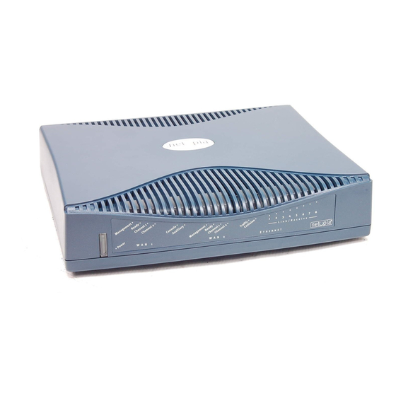
Page 22: Netopia R7100 Sdsl Router Status Lights
3-4 User’s Reference Guide Netopia R7100 SDSL Router status lights The figure below represents the Netopia R7100 status light (LED) panel. Netopia R7100 LED front panel WAN 1 The following table summarizes the meaning of the various LED states and colors: When this happens... -
Page 23: Overview
Before connecting the Netopia R7100 to any AppleTalk LANs that contain other AppleTalk routers, you should read “Routers and seeding” on page 11-3. See the later sections in this chapter for details on how to connect the Netopia R7100 to different types of networks. Readying computers on your local network PC and Macintosh computers must have certain components installed before they can communicate through the Netopia R7100. - Page 24 TCP/IP stack: This is the software that lets your PC or Macintosh communicate using Internet protocols. TCP/IP stacks must be configured with some of the same information you used to configure the Netopia R7100. There are a number of TCP/IP stacks available for PC computers. Windows 95 includes a built-in TCP/IP stack.
-
Page 25: Connecting To An Ethernet Network
Connecting to an Ethernet network The Netopia R7100 supports Ethernet connections through its eight Ethernet ports. The router automatically detects which Ethernet port is in use. You can connect either 10Base-T or EtherWave Ethernet networks to the Netopia R7100. The following table displays some important attributes of these types of Ethernet. -
Page 26: 10Base-T
Ethernet Nor- To connect your 10Base-T network to the Netopia R7100 through an Ethernet port, use a 10Base-T cable with RJ-45 connectors. If you have more than eight devices to connect, you can attach additional devices using either a 10Base-T hub... -
Page 27: Adding An External Modem
If you add devices connected through a hub, connect the hub to Ethernet port number 1 on the Netopia R7100 and set the Normal/Uplink switch to Uplink. When there are no more free ports on the 10Base-T hub, the network can be extended using EtherWave, a daisy-chainable Ethernet solution from Farallon. -
Page 28: Connecting To A Localtalk Network
HD-15 (female) Connect the male HD-15 end of the LocalTalk cable to the Auxiliary port on your Netopia R7100. Connect the other end of the cable to your LocalTalk network. You can use only one connection on the Auxiliary port. You cannot use both the PhoneNET connector and an external modem. -
Page 29: Wiring Guidelines For Phonenet Cabling
Wiring guidelines for PhoneNET cabling Topology Daisy chain Backbone 4-branch passive star* LocalTalk StarController 12-branch active star * Distance is per branch For detailed configuration instructions see Connecting to Your Local Area Network 4-7 22 gauge 24 gauge .642 mm .510 mm 4500 ft. - Page 30 4-8 User’s Reference Guide...
-
Page 31: Chapter 5 - Setting Up Your Router With The Smartstart Wizard
Once you’ve connected your router to your computer and your telecommunications line and installed a web browser, you’re ready to run the Netopia SmartStart™ Wizard. The SmartStart Wizard will help you set up the router and share the connection. The SmartStart Wizard walks you through a series of questions and based on your responses automatically configures the router for connecting your LAN to the Internet or to your remote... -
Page 32: Before Running Smartstart
SmartStart, in case you do not want to use the dynamic addressing features built in to the Netopia Router and need to restore the fixed IP address. -
Page 33: Setting Up Your Router With The Smartstart Wizard
Setting up your Router with the SmartStart Wizard The SmartStart Wizard is tailored for your platform, but it works the same way on either a PC or a Macintosh. Insert the Netopia CD, and in the desktop navigation screen that appears, launch the SmartStart Wizard application. -
Page 34: Easy Option
Check your cable connections. Be sure you have connected the router and the computer properly, using the correct cables. Refer to the Step 1 “Connect the Router” sheet in your Netopia R7100 documentation folio. Make sure the router is turned on and that there is an Ethernet connection between your computer and the router. -
Page 35: Advanced Option
first radio button. If you do this, the Address screen,” appears (shown below.) If you want to reconfigure the router with a new IP address and subnet mask, select the second radio button. If you do this, the “New IP Address screen”... -
Page 36: Sharing The Connection
Remember, the serial number is on the bottom of the router. It is also found in your documentation folio. Note: Forcing a new IP address may turn off the Netopia R7100’s IP address serving capabilities, if you assign an IP address and subnet mask outside the router’s current IP... - Page 37 Dynamic configuration (recommended) If you configure your Netopia R7100 using SmartStart, you can accept the dynamic IP address assigned by your router. The Dynamic Host Configuration Protocol (DHCP) server, which enables dynamic addressing, is enabled by default in the router. If your PC is not set for dynamic addressing, SmartStart will offer to do this for you when you launch it.
- Page 38 Subnet Mask: 255.255.255.0, or for 12-user models 255.255.255.240 This address is an example of one that can be used to configure the router with the Easy option in the SmartStart Wizard. Your ISP or network administrator may ask you to use a different IP address and...
- Page 39 Click on the Gateway tab (shown below). Under “New gateway,” enter 192.168.1.1. Click Add. This is the Netopia R7100’s pre-assigned IP address. Click OK in this window, and the next window. When prompted, reboot the computer. Note: You can also use these instructions to configure other computers on your network with manual or static IP addresses.
-
Page 40: Configuring Tcp/Ip On Macintosh Computers
Macintosh. Dynamic configuration (recommended) If you configure your Netopia R7100 using SmartStart, you can accept the dynamic IP address assigned by your router. The Dynamic Host Configuration Protocol (DHCP), which enables dynamic addressing, is enabled by default in the router. To configure your Macintosh computer for dynamic addressing do the following: Go to the Apple menu. - Page 41 Note: You can also use these instructions to configure other computers on your network with manual or static IP addresses. Be sure each computer on your network has its own IP address. Setting up your Router with the SmartStart Wizard 5-11 Select/Type:...
- Page 42 If you want to use MacIP to dynamically assign IP addresses to the Macintosh computers on your network you must install the optional AppleTalk feature set kit. Note: You cannot use MacIP dynamic configuration to configure your Netopia R7100 ISDN Router because you must first configure the router in order to enable AppleTalk.
- Page 43 These are the only fields you need to modify in these screens. Note: More information about configuring your Macintosh computer for TCP/IP connectivity through a Netopia R7100 can be found in Technote NIR_026, “Open Transport and Netopia Routers,” located on the Netopia Web site.
- Page 44 5-14 User’s Reference Guide...
-
Page 45: Chapter 6 - Console-Based Management
Console-based management is a menu-driven interface for the capabilities built in to the Netopia R7100. Console-based management provides access to a wide variety of features that the router supports. You can customize these features for your individual setup. This chapter describes how to access the console-based management screens. -
Page 46: Connecting Through A Telnet Session
Note: Alternatively, you can have a direct serial console cable connection using the provided console cable for your platform (PC or Macintosh) and the Console port on the back of the router. For more information on attaching the console cable, see Telnet software installed on the computer you will use to configure the router... -
Page 47: Configuring Telnet Software
ZTerm, included on the Netopia CD, for Macintosh computers. The Netopia R7100 back panel has a connector labeled “Console” for attaching the Router to either a PC or Macintosh computer via the serial port on the computer. (On a Macintosh computer, the serial port is called the Modem port or Printer port.) This connection lets you use the computer to configure and monitor the Netopia... -
Page 48: Navigating Through The Console Screens
Navigating through the console screens Use your keyboard to navigate the Netopia R7100’s configuration screens, enter and edit information, and make choices. The following table lists the keys to use to navigate through the console screens. -
Page 49: Chapter 7 - Easy Setup
This chapter describes how to use the Easy Setup console screens on your Netopia R7100 SDSL Router. After completing the Easy Setup console screens, your router will be ready to connect to the Internet or another remote site. Easy Setup console screens Using three Easy Setup console screens, you can: Modify a connection profile for your router for the connection to your ISP or remote location... - Page 50 If you do not see the Main Menu, verify that: The computer used to view the console screen has its serial port connected to the Netopia R7100’s Console port or an Ethernet connection to one of its Ethernet ports. See your router”...
-
Page 51: Quick Easy Setup Connection Path
Quick Easy Setup connection path This section may be all you need to do to configure your Netopia R7100 with SDSL to connect to the Internet. With DHCP and ATM FUNI (the defaults) Your Netopia R7100 with SDSL comes preconfigured with the ability to accept an IP address dynamically assigned by your ISP. - Page 52 Relay or ATM FUNI. If you select Frame Relay, see your ISP uses and press Return. Press the Down arrow key until you reach NEXT SCREEN. Press Return to bring up the next screen. Netopia R7100-C v4.3 Easy Setup... WAN Configuration...
- Page 53 PREVIOUS SCREEN Enter an IP address in decimal and dot form (xxx.xxx.xxx.xxx). Set up the basic IP & IPX attributes of your Netopia in this screen. Press the Down arrow key until the editable field labelled Domain Name is highlighted.
-
Page 54: More Easy Setup Options
14. Do this again, through the next two screens until you reach RESTART DEVICE. When RESTART DEVICE is highlighted, press Return. When prompted, select CONTINUE, and press Return. The Router will restart and your configuration settings will be activated. You can then Exit or Quit your Telnet application. -
Page 55: Easy Setup Profile
ISP or a corporate site. On a Netopia R7100 SDSL Router you can add up to 15 more connection profiles, for a total of 16, although you can only use one at a time. -
Page 56: Ip Easy Setup
7-8 User’s Reference Guide IP Easy Setup The IP Easy Setup screen is where you enter information about your Netopia Router’s: Ethernet IP address Ethernet Subnet mask Domain Name Domain Name Server IP address Default gateway IP address Consult with your network administrator to obtain the information you will need. For more information about setting up IP, see “IP Setup and Network Address Translation”... -
Page 57: Easy Setup Security Configuration
PREVIOUS SCREEN Configure a Configuration Access Name and Password here. The final step in configuring the Easy Setup console screens is to restart the Netopia R7100, so that the configuration settings take effect. Select RESTART DEVICE. A prompt asks you to confirm your choice. -
Page 58: Configuring Frame Relay
7-10 User’s Reference Guide Configuring Frame Relay Frame Relay is an alternative datalink encapsulation method for use over unswitched connections. If this does not apply to your connection, you can skip the corresponding sections. You can specify Frame relay as your Datalink Encapsulation method in either of two ways: “Easy Setup Frame Relay screens”... -
Page 59: Wan Configuration Frame Relay Screens
WAN Configuration Frame Relay screens The SDSL Line Configuration menu also offers the options of either PPP, HDLC, or Frame Relay as your datalink encapsulation method. Main Menu Clock Source... Data Link Encapsulation... Aux Serial Port... Configuration SDSL Line Configuration Network +-------------+ +-------------+... -
Page 60: Frame Relay Configuration
7-12 User’s Reference Guide Frame Relay configuration If you chose Frame Relay as your datalink encapsulation type you can now configure the Frame Relay options from the WAN Configuration menu. Return/Enter for WAN line configuration. From here you will configure yours and the remote sites' WAN information. From the WAN Configuration screen, select WAN Setup, then select the Frame Relay Configuration option and press Return. - Page 61 DLCIs or DLCIs other than 16, or an LMI setting other than No LMI. In that case there may be no need to statically configure DLCIs at all since the router may be able to detect what DLCIs are configured between it and the DSLAM.
-
Page 62: Frame Relay Dlci Configuration
Frame Relay DLCI configuration If you selected None as your LMI Type then you will need to manually configure your DLCIs. A Frame Relay DLCI is a set of parameters that tells the Netopia Router how to initially connect to a remote destination. - Page 63 To go to the Frame Relay DLCI configuration screen, select Frame Relay DLCI Configuration in the WAN Configuration screen. Add, delete, and modify DLCIs from here. Displaying a Frame Relay DLCI configuration table To display a view-only table of the Frame Relay DLCIs, select Display/Change DLCIs in the Frame Relay DLCI Configuration screen, and press Return.
- Page 64 7-16 User’s Reference Guide Changing a Frame Relay DLCI configuration To modify a Frame Relay DLCI configuration, select Display/Change DLCIs in the Frame Relay DLCI Configuration screen. Select a DLCI Name from the table and press Return to go to the Change DLCI screen. The parameters in this screen are the same as the parameters in the Add DLCI screen.
- Page 65 This is accomplished by giving a DLCI Name to a DLCI Number. Select DLCI Enabled and toggle it to Yes to activate the profile. If you disable this profile, the Netopia Router will automatically disable and block access to a specific remote DLCI.
- Page 66 7-18 User’s Reference Guide Identifier). The setting defaults to 64000, but you may modify the committed burst size by toggling the selection in the Use Default field to No. You can then enter a different committed burst size in the Value field.
- Page 68 User’s Reference Guide...
-
Page 69: Chapter 8 - Wan And System Configuration
This chapter describes how to use the console-based management screens to access and configure advanced features of your Netopia R7100 SDSL Router. You can customize these features for your individual setup. These menus provide a powerful method for experienced users to set up their router’s connection profiles and system configuration. - Page 70 Enter Information supplied to you by your telephone company. The Clock Source may be either Network or Internal. If you select Network (the default), the Netopia R7100 functions in customer premise equipment (CPE) mode. This mode is the normal mode for communicating with an ISP.
-
Page 71: The Default Profile
IP Address, you need not explicitly configure a connection profile, and the default behavior of the router will be to connect automatically once it is powered on. If Must Match a Defined Profile is set to No, then an IP Enabled item is visible. Toggling this item to Yes (the default) or No controls whether or not IP will be supported on the DSL link. -
Page 72: Ip Parameters (Default Profile) Screen
Return/Enter accepts * Tab toggles * ESC cancels. The Netopia R7100 SDSL Router always acts as a DHCP client on the DSL link when using a Default Profile. The DHCP server will supply a local IP address and subnet mask. For a DSL link, Network Address Translation (NAT) is enabled by default in the Default Profile. -
Page 73: Ipx Parameters (Default Profile) Screen
Through the console port, using a local terminal (see page 6-3) You can also retrieve the Netopia R7100’s configuration information and remotely set its parameters using the Simple Network Management Protocol (see Open a Telnet connection to the router’s IP address; for example, “192.168.1.1.”... -
Page 74: Navigating Through The System Configuration Screens
Select Network Protocols and press Return. The Network Protocols screen appears. Select IP Setup and press Return. The IP Setup screen appears. To go back in this sequence of screens, use the Escape key. Netopia R7100 v4.3 Easy Setup... WAN Configuration... -
Page 75: System Configuration Features
System configuration features The Netopia R7100 SDSL Router’s default settings may be all you need to configure your Netopia R7100. Some users, however, require advanced settings or prefer manual control over the default selections. For these users, the Netopia R7100 provides system configuration options. -
Page 76: Network Protocols Setup
8-8 User’s Reference Guide Network protocols setup These screens allow you to configure your network’s use of the standard networking protocols: IP: Details are given in “IP Setup and Network Address Translation” on page IPX: Details are given in “IPX Setup” on page 10-1. AppleTalk: Details are given in Note: AppleTalk requires the optional AppleTalk feature expansion kit. -
Page 77: Console Configuration
Select Current Date and enter the date in the appropriate format. Use one- or two-digit numbers for the month and day, and the last two digits of the current year. The date’s numbers must be separated by forward slashes (/). Select Current Time and enter the time in the format HH:MM, where HH is the hour (using either the 12-hour or 24-hour clock) and MM is the minutes. -
Page 78: Snmp (Simple Network Management Protocol)
You can upgrade your Netopia R7100 by adding new feature sets through the Upgrade Feature Set utility. See the release notes that came with your router or feature set upgrade, or visit the Netopia Web site at www.netopia.com for information on new feature sets, how to obtain them, and how to install them on your Netopia R7100. -
Page 79: Installing The Syslog Client
You can specify the UNIX syslog Facility to use by selecting the Facility pop-up. Installing the Syslog client The Goodies folder on the Netopia CD contains a Syslog client daemon program that can be configured to report the WAN events you specified in the Logging Configuration screen. - Page 80 8-12 User’s Reference Guide...
-
Page 81: Chapter 9 - Ip Setup And Network Address Translation
The Netopia R7100 uses Internet Protocol (IP) to communicate both locally and with remote networks. This chapter shows you how to configure the Router to route IP traffic. You also learn how to configure the router to serve IP addresses to hosts on your local network. - Page 82 Each profile can have NAT enabled. When NAT is enabled, the Netopia R7100 can use either a statically assigned IP address or one dynamically assigned each time the router connects to the ISP. While a dynamically assigned IP address offers the ISP more flexibility, it does have an important limitation: the router requires a static IP address to support Web, FTP, or...
-
Page 83: Using Network Address Translation
Pick a network number for your local network (referred to as the internal network). This can be any IP address range you want. The Netopia R7100 SDSL Router has a default IP address of 192.168.1.1. You may choose to change this address to match a pre-existing addressing scheme. For this example, we will use 10.0.0.0. - Page 84 Select IP Addressing and, from the pop-up menu, choose the IP routing method that your ISP or network administrator specifies (either Numbered or Unnumbered). For more information see “Understanding IP Addressing.” IP Profile Parameters Unnumbered 0.0.0.0 0.0.0.0 0.0.0.0 Both v2 (multicast) Appendix C, “Understanding Netopia NAT Behavior.” Appendix B,...
- Page 85 If your ISP uses numbered (interface-based) routing, select Local WAN IP Address and enter the local WAN address your ISP gave you. Then select Local WAN IP Mask and enter the WAN subnet mask of the remote site you will connect to. The default address is 0.0.0.0, which allows for dynamic addressing, meaning that your ISP assigns an address via DHCP each time you connect.
-
Page 86: Associating Port Numbers With Nodes
9-6 User’s Reference Guide When using numbered interfaces, the Netopia Router will use its local WAN IP address and subnet mask to send packets to the remote router. Both routers have WAN IP addresses and subnet masks associated with the connection. -
Page 87: Advanced Ip/Ipx Router Configuration Options
Telnet uses port number 23 SNMP uses port number 161 To help direct incoming IP traffic to the appropriate server, the Netopia R7100 lets you associate these and other port numbers with distinct IP addresses on your internal LAN using exported services. See page 9-11 for details. -
Page 88: Connection Profiles
Return accepts * ESC cancels * Left/Right moves insertion point * Del deletes. Configure a new Conn. Profile. Finished? On a Netopia R7100 SDSL Router you can add up to 15 more connection profiles, for a total of 16, although only one can be used at a time. - Page 89 Address Translation Enabled: IP Addressing... Local WAN IP Address: Local WAN IP Mask: Remote IP Address: Remote IP Mask: Filter Set... Remove Filter Set Receive RIP: Transmit RIP: Configure IP requirements for a remote network connection here. Toggle or enter any IP Parameters you require and return to the Add Connection Profile screen by pressing Escape.
-
Page 90: Network Address Translation Guidelines
Observe the following guidelines when using Network Address Translation. The router can export only one local IP address per UDP/TCP port, so you can have just one machine available for a given service, such as one FTP server. However, some services, such as Web servers (www-http servers), allow you to change the UDPTCP port on both the server and client. -
Page 91: Ip Setup
Main Menu The IP Setup options screen is where you configure the Ethernet side of the Netopia R7100. The information you enter here controls how the router routes IP traffic. Consult your network administrator or Internet service provider to obtain the IP setup information (such as the Ethernet IP address, Ethernet subnet mask, default IP gateway and Primary Domain Name Server IP address) you will need before changing any of the settings in this screen. - Page 92 Routing Information Protocol (RIP) is needed if there are IP routers on other segments of your Ethernet network that the Netopia R7100 needs to recognize. If this is the case select Receive RIP and select v1, v2, or Both from the popup menu. With Receive RIP set to “v1,” the Netopia R7100’s Ethernet port will accept routing information provided by RIP packets from other routers that use the same subnet mask.
- Page 93 Exports, Add Export, and Delete Export. Return/Enter to configure UDP/TCP Port-to-IP Address redirection. Select Add Export. The Add Exported Service screen appears. Service... Local Server's IP Address: ADD EXPORT NOW IP Setup and Network Address Translation 9-13 Exported Services (Local Port to IP Address Remapping) Show/Change Exports...
- Page 94 Select any of the services/ports and press Return to associate it with the address of a server on your local area network. For example, if we select www-http 80, press Return, and type 10.0.0.2, the Netopia R7100 redirects any incoming traffic destined for a Web server to address 10.0.0.2.
-
Page 95: Ip Subnets
Press Escape when you are finished configuring exported services. You are returned to the IP Setup screen. Ethernet IP Address: Ethernet Subnet Mask: Define Additional Subnets... Default IP Gateway: Primary Domain Name Server: Secondary Domain Name Server: Domain Name: Receive RIP: Transmit RIP: Static Routes... - Page 96 All eight row labels are always visible, regardless of the number of subnets configured. To add an IP subnet, enter the Netopia R7100’s IP address on the subnet in the IP Address field in a particular row and the subnet mask for the subnet in the Subnet Mask field in that row.
-
Page 97: Static Routes
Static routes are IP routes that are maintained manually. Each static route acts as a pointer that tells the Netopia R7100 how to reach a particular network. However, static routes are used only if they appear in the IP routing table, which contains all of the routes used by the Netopia R7100 (see Static routes are helpful in situations where a route to a network must be used and other means of finding the... - Page 98 9-18 User’s Reference Guide The Static Routes screen will appear. Configure/View/Delete Static Routes from this and the following Screens. Viewing static routes To display a view-only table of static routes, select Display/Change Static Route. The table shown below will appear. +-Dest.
- Page 99 Select Destination Network Subnet Mask and enter the subnet mask used by the destination network. Select Next Gateway IP Address and enter the IP address for the router that the Netopia R7100 will use to reach the destination network. This router does not necessarily have to be part of the destination network, but it must at least know where to forward packets destined for that network.
- Page 100 If the static route conflicts with a connection profile, the connection profile will always take precedence. To make sure that the static route is known only to the Netopia R7100, select Advertise Route Via RIP and toggle it to No. To allow other RIP-capable routers to know about the static route, select Advertise Route Via RIP and toggle it to Yes.
-
Page 101: Ip Address Serving
Menu Configuration In addition to being a router, the Netopia R7100 is also an IP address server. There are four protocols it can use to distribute IP addresses. The first, called Dynamic Host Configuration Protocol (DHCP), is widely supported on PC networks, as well as Apple Macintosh computers using Open Transport and computers using the UNIX operating system. - Page 102 AppleTalk kit installed) are automatically enabled. Select Number of Client IP Addresses and enter the total number of contiguous IP addresses that the Netopia R7100 will distribute to the client machines on your local area network. 12-user models are limited to twelve IP addresses.
- Page 103 If you have configured multiple Ethernet IP subnets, the appearance of the IP Address Serving screen is altered slightly: Configure Address Pools... Serve DHCP Clients: DHCP NetBios Options... Serve BOOTP Clients: Serve Dynamic WAN Clients: Serve MacIP/KIP Clients: MacIP/KIP Static Options... The first three menu items are hidden, and Configure Address Pools appears instead.
-
Page 104: Ip Address Pools
The Client Gateway column allows you to specify the default gateway address that will be provided to clients served an address from the corresponding pool. The value defaults to the Netopia R7100’s IP address on the corresponding subnet (or the Netopia R7100’s default gateway, if that gateway is located on the subnet in question). - Page 105 When requesting an address, a client may provide a client identifier, or, if it does not, the Netopia R7100 may construct a pseudo-client identifier for the client. When the client subsequently requests an address, the Netopia R7100 will attempt to serve the address previously associated with the client identifier.
-
Page 106: Dhcp Netbios Options
9-26 User’s Reference Guide DHCP NetBIOS Options If your network uses NetBIOS, you can enable the Netopia R7100 to use DHCP to distribute NetBIOS information. NetBIOS stands for Network Basic Input/Output System. It is a layer of software originally developed by IBM and Sytek to link a network operating system with specific hardware. - Page 107 From the NetBios Type pop-up menu, select the type of NetBIOS used on your network. Serve NetBios Type: NetBios Type... Serve NetBios Scope: NetBios Scope: Serve NetBios Name Server: NetBios Name Server IP Addr: To serve DHCP clients with the NetBIOS scope, select Serve NetBios Scope and toggle it to Yes. Select NetBios Scope and enter the scope.
-
Page 108: Macip (Kip Forwarding) Setup
Ethernet), they must use a MacIP (AppleTalk–IP) gateway. The optional Netopia AppleTalk feature enhancement kit provides for this service. A MacIP gateway converts network traffic into the correct format for AppleTalk or IP, depending on the traffic’s destination. The MacIP gateway can also distribute IP addresses to AppleTalk computers on the network. - Page 109 The MacIP (KIP) Forwarding Setup screen tells the Netopia R7100 how many static addresses to allocate for MacIP/KIP clients. The addresses must fall within the address pool from the previous screen. Enter the number of static MacIP addresses to reserve.
- Page 110 9-30 User’s Reference Guide...
-
Page 111: Chapter 10 - Ipx Setup
Internetwork Packet Exchange (IPX) is the network protocol used by Novell NetWare networks. This chapter shows you how to configure the Netopia R7100 for routing data using IPX. You also learn how to configure the router to serve IPX network addresses. -
Page 112: Ipx Address
10-2 User’s Reference Guide IPX address An IPX address consists of a network number, a node number, and a socket number. An IPX network number is composed of eight hexadecimal digits. The network number must be the same for all nodes on a particular physical network segment. -
Page 113: Netbios
IPX spoofing The Netopia R7100 has several IPX features designed to restrict the traffic on the dial-up link when the unit is not sending or receiving IPX data. When the link is idle and a user is logged into a Novell server, the server will send “keep-alive”... - Page 114 IPX network to only those required by remote users connecting to the Netopia R7100. An Ethernet SAP filter must be used with networks that have so many servers advertised that the Netopia R7100 would otherwise exhaust its internal memory storing server entries.
-
Page 115: Ipx Routing Tables
IPX routing tables provide information on current IPX routes and services. To go to the IPX Routing Table screen, select IPX Routing Table in the Statistics & Logs screen. This table shows detailed information about current IPX network routes. Net Addr-Hops-Ticks-Type--Status-Interface--------------via Router------------ -----------------------------------SCROLL UP---------------------------------- 00000020... - Page 116 10-6 User’s Reference Guide...
-
Page 117: Chapter 11 - Appletalk Setup
This chapter discusses the concept of AppleTalk routing and how to configure AppleTalk setup for a Netopia R7100 with the AppleTalk kit installed. AppleTalk support is available as a separate kit for the Netopia R7100 SDSL Router. Skip this chapter if you do not have the AppleTalk kit. - Page 118 AppleTalk tells them apart according to an additional part of their addresses: the network number. The Netopia R7100 assigns a unique network number to each member network. In terms of the city street metaphor, the network number is similar to the name of the street. Putting a network number together with a node number fully specifies the address of a node on an internet.
-
Page 119: Macip
When two networks using AppleTalk communicate with each other through a network based on the Internet Protocol, they are said to be “tunneling” through the IP network. The Netopia R7100 uses AURP to allow your AppleTalk network to tunnel to designated AppleTalk partner networks, as well as to accept connections from remote AppleTalk networks tunneling to your AppleTalk LAN. -
Page 120: Installing Appletalk
These scenarios may guide you in deciding how to set the router’s seeding: If the Netopia R7100 is the only router on your network, you must set it to either hard seeding or soft seeding. The default is soft seeding. - Page 121 Main Menu The Netopia Feature Set Upgrade screen appears. You may be able to extend the features of your Netopia by purchasing a 'Software Upgrade'. notes that came with your Netopia or visit the Netopia Communications web site at www.netopia.com.
-
Page 122: Configuring Appletalk
Note: Your EtherTalk network number and zone name must match the values in use on the EtherTalk network. If another router is already present on the EtherTalk network that you will be connecting to the Netopia R7100, use the zone names and network numbers used by that router for that EtherTalk network. -
Page 123: Localtalk Setup
LocalTalk network. If another router is already present on the LocalTalk network that you will be connecting to the Netopia R7100, use the zone name and network number used by that router for that LocalTalk network. Otherwise, your LocalTalk network may experience routing conflicts. -
Page 124: Aurp Setup
11-8 User’s Reference Guide As an alternative, you can set LocalTalk seeding to soft seeding and let the Netopia R7100 receive the zone name and network number from the other router. Select LocalTalk Net Number and enter the desired network number. - Page 125 Example: Site A has an AURP tunnel to site B. Both sides have multiple zones defined on the EtherTalk port and a unique zone on their LocalTalk ports. If side A has indicated that one of its EtherTalk zones is the Free Trade Zone and has opted to use the Free Trade Zone option for its tunnel to B, then only this Free Trade Zone will show up on side B and only those machines or services in the Free Trade Zone will be accessible to side B.
- Page 126 11-10 User’s Reference Guide Partner IP Address or Domain Name: 176.163.8.134 Initiate Connection: Restrict to Free Trade Zone: The Change AURP Partner screen has all the values you entered when you added that partner. All of these values may be modified in this screen. Deleting an AURP partner To delete an AURP partner, in the AURP Setup screen select Delete Partner and press Return.
- Page 127 The AURP tickle timer is a parameter that you can set anywhere between 0 and 100 hours. This parameter tells the AURP partners when to send out an AURP tickle packet. If this value is set to 0, the Netopia R7100 will never send out a tickle packet.
- Page 128 11-12 User’s Reference Guide When network number remapping is enabled, you must choose a safe range of network numbers as a destination for the remapping. A safe range of network numbers does not intersect your local AppleTalk network’s range of network numbers. To choose a destination range for the remapping, select From under Remap into Range and enter a starting value.
-
Page 129: Quick View Status Overview
“SmartView” on page 12-16 Quick View status overview You can get a useful, overall status report from the Netopia R7100 in the Quick View screen. To go to the Quick View screen, select Quick View in the Main Menu. The Quick View screen has three status sections:... -
Page 130: General Status
IPX Address: The Netopia R7100’s IPX address, entered in the IPX Setup screen. EtherTalk Address: The Netopia R7100’s AppleTalk address on its EtherTalk Phase II interface, entered in the EtherTalk Phase II Setup screen (only if the optional AppleTalk feature set is installed). -
Page 131: Current Status
ISDN caller identification (if available). Status lights This section shows the current real-time status of the Netopia R7100’s status lights (LEDs). It is useful for remotely monitoring the router’s status. The Quick View screen’s arrangement of LEDs corresponds to the physical arrangement of LEDs on the router. -
Page 132: Statistics & Logs
Main Menu When you are troubleshooting your Netopia R7100, the Statistics & Logs screens provide insight into the recent event activities of the router. From the Main Menu go to Statistics & Logs and select one of the options described in the sections below. -
Page 133: Event Histories
You can view two different event histories: one for the router’s system and one for the WAN. The Netopia R7100’s built-in battery backup prevents loss of event history from a shutdown or reset. - Page 134 12-6 User’s Reference Guide WAN Event History The WAN Event History screen lists a total of 128 events on the WAN. The most recent events appear at the top. -Date-----Time-----Event------------------------------------------------------ ----------------------------------SCROLL UP----------------------------------- 07/03/98 13:59:06 07/03/98 13:59:05 07/03/98 13:59:05 >>WAN: data link activated at 1040 Kbps 07/03/98 13:58:32 --Device restarted----------------------------------------- 07/03/98 12:46:39 --Device restarted----------------------------------------- 07/03/98 11:45:57 --Device restarted-----------------------------------------...
-
Page 135: Routing Tables
To clear the Device Event History, select Clear History and press Return. Routing tables You can view all of the IP, IPX, and AppleTalk routes in the Netopia R7100’s IP, IPX, and AppleTalk routing tables, respectively. To go to a routing table screen, select the routing table you are interested in from the Statistics & Logs screen. - Page 136 12-8 User’s Reference Guide IP routing table In the Statistics & Logs screen, select IP Routing Table and press Return. The IP routing table displays all of the IP routes currently known to the Netopia R7100. Network Address-Subnet Mask-----via Router------Port------------------Type---- ----------------------------------SCROLL UP----------------------------------- 0.0.0.0...
- Page 137 IPX Sap Bindery table In the Statistics & Logs screen, select IPX Sap Bindery Table and press Return. The IPX Sap Bindery table displays all of the IPX Sap Bindery routes currently known to the Netopia R7100. AppleTalk routing table In the Statistics &...
-
Page 138: Served Ip Addresses
Pkts Fwded: The number of packets sent to the router shown. Served IP Addresses You can view all of the IP addresses currently being served by the Netopia R7100 SDSL Router from the Served IP Addresses screen. From the Statistics & Logs menu, select Served IP Addresses. The Served IP Addresses screen appears. - Page 139 The IP Address Lease Management screen appears. Reset All Leases Release BootP Leases Reclaim Declined Addresses Hit RETURN/ENTER, you will return to the previous screen. This screen has three options: Reset All Leases: Resets all current IP addresses leased through DHCP without waiting for the default one–hour lease period to elapse Release BootP Leases: Releases any BootP leases that may be in place, and which may no longer be required.
-
Page 140: System Information
AppleTalk MIB I (RFC 1243) Netopia MIB These MIBs are on the Netopia R7100 CD included with the Netopia R7100. Load these MIBs into your SNMP management software in the order they are listed here. Follow the instructions included with your SNMP manager on how to load MIBs. -
Page 141: The Snmp Setup Screen
Select System Contact and enter the name of the person responsible for maintaining the router. System Name, System Location, and System Contact set the values returned by the Netopia R7100 SNMP agent for the SysName, SysLocation, and SysContact objects, respectively, in the MIB II system group. Although optional, the information you enter in these items can help a system administrator manage the network more efficiently. -
Page 142: Snmp Traps
SNMP traps An SNMP trap is an informational message sent from an SNMP agent (in this case, the Netopia R7100) to a manager. When a manager receives a trap, it may log the trap as well as generate an alert message of its own. - Page 143 Return/Enter to modify an existing Trap Receiver. Navigate from here to view, add, modify and delete IP Trap Receivers. Setting the IP trap receivers Select Add IP Trap Receiver. Select Receiver IP Address or Domain Name. Enter the IP address or domain name of the SNMP manager you want to receive the trap.
-
Page 144: Smartview
12-16 User’s Reference Guide SmartView This section discusses SmartView, the Netopia R7100’s device and network web-based monitoring tool. This tool can provide statistical information, report on current network status, record events, and help in diagnosing and locating problems. SmartView overview SmartView is a Java-based applet that runs in a Web browser window. -
Page 145: Navigating Smartview
The information you can view about your router using SmartView is shown in the table below: Navigating SmartView You access the SmartView monitor by launching your web browser and entering the URL: http://router_IP_Address/smartview.html where router_IP_address is the address of your router. -
Page 146: General Machine Information Page
In addition to the static machine information about your router, such as model and firmware version, SmartView displays a real-time visual representation of the Netopia R7100’s status lights (LEDs). This is particularly useful if the router is located out of visual range, such as in a wiring closet. -
Page 147: Event History Pages
You can view two different event histories: one for the router’s system and one for the WAN. The Netopia R7100’s built-in battery backup prevents loss of event history from a shutdown or reset. - Page 148 12-20 User’s Reference Guide WAN Event History page...
-
Page 149: Standard Html Web-Based Monitoring Pages
You access the web-based monitoring pages by launching your web browser and entering the URL: http://router_IP_address where router_IP_address is the address of your router. The default address is 198.162.1.1. To view event histories, click the Statistics icon. To go to SmartView if your browser is Java-enabled, click the SmartView icon. - Page 150 12-22 User’s Reference Guide...
-
Page 151: Suggested Security Measures
User accounts When you first set up and configure the Netopia R7100, no passwords are required to access the configuration screens. Anyone could tamper with the router’s configuration by simply connecting it to a console. However, by adding user accounts, you can protect the most sensitive screens from unauthorized access. User accounts are composed of name/password combinations that can be given to authorized users. - Page 152 13-2 User’s Reference Guide Caution! You are strongly encouraged to add protection to the configuration screens. Unprotected screens could allow an unauthorized user to compromise the operation of your entire network. Once user accounts are created, users who attempt to access protected screens will be challenged. Users who enter an incorrect name or password are returned to a screen requesting a name/password combination to access the Main Menu.
-
Page 153: Dial-In Console Access
Remote modem terminal emulator setups can dial in to the modem line and establish a remote console session, even though they are not using PPP. This allows Netopia Inc.'s “Up and Running, Guaranteed!” department or other administrator with the appropriate security to remotely configure your router for you. -
Page 154: Enable Smartstart/Smartview/Web Server
SmartStart. To prevent access to these features toggle this option to No. Telnet access Telnet is a TCP/IP service that allows remote terminals to access hosts on an IP network. The Netopia R7100 supports Telnet access to its configuration screens. Caution! You should consider password-protecting or restricting Telnet access to the Netopia R7100 if you suspect there is a chance of tampering. -
Page 155: How Filter Sets Work
Security 13-5 How filter sets work A filter set acts like a team of customs inspectors. Each filter is an inspector through which incoming and outgoing packages must pass. The inspectors work as a team, but each inspects every package individually. Each inspector has a specific task. - Page 156 13-6 User’s Reference Guide If the package does not match the first inspector’s criteria, it goes to the second inspector, and so on. You can see that the order of the inspectors in the line is very important. For example, let’s say the first inspector’s orders are to send along all packages that come from Rome, and the second inspector’s orders are to reject all packages that come from France.
-
Page 157: How Individual Filters Work
This rule applies to Telnet packets that come from a host with the IP address 199.211.211.17. If a match occurs, the packet is blocked. Here is what this rule looks like when implemented as a filter on the Netopia R7100: +-#--Source IP Addr--Dest IP Addr-----Proto-Src.Port-D.Port--On?-Fwd-+ +--------------------------------------------------------------------+ 199.211.211.17... - Page 158 13-8 User’s Reference Guide By matching on a port number, a filter can be applied to selected TCP or UDP services, such as Telnet, FTP, and World Wide Web. The tables below show a few common services and their associated port numbers. TFTP Port number comparisons A filter can also use a comparison option to evaluate a packet’s source or destination port number.
- Page 159 Putting the parts together When you display a filter set, its filters are displayed as rows in a table: +-#---Source IP Addr---Dest IP Addr-----Proto-Src.Port-D.Port--On?-Fwd-+ +----------------------------------------------------------------------+ 192.211.211.17 0.0.0.0 0.0.0.0 0.0.0.0 0.0.0.0 +----------------------------------------------------------------------+ The table’s columns correspond to each filter’s attributes: #: The filter’s priority in the set. Filter number 1, with the highest priority, is first in the table. Source IP Addr: The packet source IP address to match.
- Page 160 13-10 User’s Reference Guide Filtering example #1 Returning to our filtering rule example from above (see Start with the rule, then fill in the filter’s attributes: The rule you want to implement as a filter is: Block all Telnet attempts that originate from the remote host 199.211.211.17. The host 199.211.211.17 is the source of the Telnet packets you want to block, while the destination address is any IP address.
-
Page 161: Design Guidelines
+-#---Source IP Addr---Dest IP Addr-----Proto-Src.Port-D.Port--On?-Fwd-+ +----------------------------------------------------------------------+ 200.233.14.0 +----------------------------------------------------------------------+ This filter blocks any packets coming from a remote network with the IP network address 200.233.14.0. The 0 at the end of the address signifies any host on the class C IP network 200.233.14.0. If, for example, the filter is applied to a packet with the source IP address 200.233.14.5, it will block it. -
Page 162: Working With Ip Filters And Filter Sets
13-12 User’s Reference Guide An approach to using filters The ultimate goal of network security is to prevent unauthorized access to the network without compromising authorized access. Using filter sets is part of reaching that goal. Each filter set you design will be based on one of the following approaches: That which is not expressly prohibited is permitted. -
Page 163: Adding A Filter Set
View, change, or delete individual filters and filter sets. The sections below explain how to execute these steps. Adding a filter set You can create up to eight different custom filter sets. Each filter set can contain up to 16 output filters and up to 16 input filters. - Page 164 The Netopia R-Series Router Packets in the Netopia R7100 pass through an input filter if they originate in the WAN and through an output filter if they’re being sent out to the WAN. The process for adding input and output filters is exactly the same. The main difference between the two involves their reference to source and destination.
- Page 165 Enter the IP specific information for this filter. To make the filter active in the filter set, select Enabled and toggle it to Yes. If Enabled is toggled to No, the filter can still exist in the filter set, but it will have no effect. If you want the filter to forward packets that match its criteria to the destination IP address, select Forward and toggle it to Yes.
-
Page 166: Viewing Filter Sets
13-16 User’s Reference Guide 10. When you are finished configuring the filter, select ADD THIS FILTER NOW to save the filter in the filter set. Select CANCEL to discard the filter and return to the Add IP Filter Set screen. Viewing filters To display a view-only table of input (output) filters, select Display/Change Input Filter or Display/Change Output Filter in the Add IP Filter Set screen. -
Page 167: Modifying Filter Sets
filter set. A sample IP filter set This section contains the settings for a filter set called Basic Firewall, which is part of the Netopia R7100’s factory configuration. Basic Firewall blocks undesirable traffic originating from the WAN (in most cases, the Internet), but passes all traffic originating from the LAN. - Page 168 13-18 User’s Reference Guide The five input filters and one output filter that make up Basic Firewall are shown in the table below. Input filter Setting Enabled Forward Source IP 0.0.0.0 address Source IP 0.0.0.0 address mask Dest. IP 0.0.0.0 address Dest.
- Page 169 Basic Firewall is suitable for a LAN containing only client hosts that want to access servers on the WAN, but not for a LAN containing servers providing services to clients on the WAN. Basic Firewall’s general strategy is to explicitly pass WAN-originated TCP and UDP traffic to ports greater than 1023. Ports lower than 1024 are the service origination ports for various Internet services such as FTP, Telnet, and the World Wide Web (WWW).
- Page 170 AURP tunnel. To allow an AURP tunnel between a remote AURP router with the IP address a.b.c.d (corresponding to a numbered IP address such as 163.176.8.243) and a local AURP router (including the Netopia R7100 itself), insert the following input filter ahead of the current input filter 1: Enabled: Yes Forward: Yes Source IP Address: a.b.c.d...
-
Page 171: Ipx Filters
IPX filters Main Menu IPX packet filters work very similarly to IP packet filters. They filter data traffic coming from or going to remote IPX networks. IPX filters can be set up to pass or discard IPX packets based on a number of user-defined criteria. -
Page 172: Ipx Packet Filters
13-22 User’s Reference Guide The items in the IPX Filters and Filter Sets screen are grouped into four areas: IPX packet filters IPX packet filter sets IPX SAP filters IPX SAP filter sets The following sections explain the items in each of these areas. IPX packet filters For each IPX packet filter, you can configure a set of parameters to match on the source or destination attributes of IPX data packets coming from or going to the WAN. -
Page 173: Ipx Packet Filter Sets
Select Filter Name and enter a descriptive name for the filter. To specify a source network for the filter to match on, select Source Network and enter an IPX network address. To specify a source node for the filter to match on, select Source Node Address and enter an IPX node address. - Page 174 13-24 User’s Reference Guide Add Packet Filter Set Filter Set Name: Show Filters/Change Action on Match... Append Filter... Remove Filter... ADD FILTER SET NOW Return accepts * ESC cancels * Left/Right moves insertion point * Del deletes. Configure an IPX Filter Set here. You must ADD FILTER SET NOW to save. Follow these steps to configure the new packet filter set: Select Filter Set Name and enter a descriptive name for the filter set.
-
Page 175: Ipx Sap Filters
To add a filter to the filter set, select Append Filter to display a table of filters. Select a filter from the table and press Return to add it to the filter set. The default action of newly added filters is to not forward packets that match their criteria. - Page 176 (no characters), and ? to match any single character in the server’s name. For example, the filter could match on the server name “NETOPIA” with “NETO*”, “NETO?IA”, and “NETOPIA*”. To specify a socket for the filter to match on, select Socket and enter an IPX socket number.
-
Page 177: Ipx Sap Filter Sets
IPX SAP filter sets Before IPX SAP filters can be used, they must be grouped into sets. A SAP filter can be part of more than one filter set. Viewing and modifying SAP filter sets To display a table of IPX SAP filter sets, select Display/Change IPX SAP Filter Sets in the IPX Filters and Filter Sets screen to display a list of filter sets. - Page 178 13-28 User’s Reference Guide Set whether filters forward or drop matching packets here. Select a filter and toggle the entry forwarding action to Yes (pass) or No (discard). To add a filter to the filter set, select Append Filter in the Add SAP Filter Set screen to display a table of filters.
-
Page 179: Firewall Tutorial
Firewall tutorial General firewall terms Filter rule: A filter set is comprised of individual filter rules. Filter set: A grouping of individual filter rules. Firewall: A component or set of components that restrict access between a protected network and the Internet, or between two networks. -
Page 180: Firewall Design Rules
13-30 User’s Reference Guide Example TCP/UDP Ports TCP Port 20/21 Firewall design rules There are two basic rules to firewall design: “What is not explicitly allowed is denied.” “What is not explicitly denied is allowed.” The first rule is far more secure, and is the best approach to firewall design. It is far easier (and more secure) to allow in or out only certain services and deny anything else. - Page 181 and a packet goes through these rules destined for FTP, the packet would pass through the first filter rule (WWW), match the second rule (FTP), and the packet is allowed through. Even though the next rule is to deny all FTP traffic, the FTP packet will never make it to this rule.
-
Page 182: Filter Basics
In the source or destination IP address fields, the IP address that is entered must be the network address of the subnet. A host address can be entered, but the applied subnet mask must be 32 bits (255.255.255.255). The Netopia R7100 has the ability to compare source and destination TCP or UDP ports. These options are as follows:... -
Page 183: Example Filters
Any port less than or equal to the port defined Matches only the port defined Matches the port or any port greater Matches anything greater than the port defined Incoming Packet Filter Netopia 200.1.1.0 (Source IP Network Address) 255.255.255.128 (Source IP Mask) Forward = No... - Page 184 This incoming IP packet (10000000) has a source IP address that does not match the network address in the Source IP Address field (00000000) in the Netopia R7100. This rule will forward this packet because the packet does not match.
- Page 185 Since the Source IP Network Address in the Netopia R7100 is 01100000, and the source IP address after the logical AND is 1011000, this rule does not match and this packet will be passed. Example 4 Filter Rule: Incoming packet has the source address of 200.1.1.104.
- Page 186 13-36 User’s Reference Guide Since the Source IP Network Address in the Netopia R7100 is 01100000, and the source IP address after the logical AND is 01100000, this rule does match and this packet will NOT be passed. This rule masks off a...
-
Page 187: Chapter 14 — Utilities And Diagnostics
A number of utilities and tests are available for system diagnostic and control purposes. This section covers the following topics: “Ping” on page 14-2 “Trace Route” on page 14-4 “Telnet client” on page 14-5 “Disconnect Telnet console session” on page 14-6 “Factory defaults”... -
Page 188: Ping
(Ping-capable) IP host. Each time the target host receives a Ping packet, it returns a packet to the original sender. Ping allows you to see whether a particular IP destination is reachable from the Netopia R7100. You can also ascertain the quality and reliability of the connection to the desired destination by studying the Ping test’s statistics. - Page 189 Ping packets. Note that the second return Ping packet is considered to be late because it is not received by the Netopia R7100 before the third Ping packet is sent. The first and third return Ping packets are on time.
-
Page 190: Trace Route
The time-to-live (TTL) value for each Ping packet sent by the Netopia R7100 is 255, the maximum allowed. The TTL value defines the number of IP routers that the packet can traverse. Ping packets that reach their TTL value are dropped, and a “destination unreachable”... -
Page 191: Telnet Client
Select Use Reverse DNS to learn the names of the routers between the Netopia Router and the destination router. The default is Yes. Select START TRACE ROUTE and press Return. A scrolling screen will appear that lists the destination, number of hops, IP addresses of each hop, and DNS names, if selected. -
Page 192: Disconnect Telnet Console Session
If you select Continue, you will immediately terminate your session. Factory defaults You can reset the Netopia R7100 to its factory default settings. In the Utilities & Diagnostics screen, select Revert to Factory Defaults and press Return. Select CONTINUE in the dialog box and press Return. The Netopia R7100 will reboot and its settings will return to the factory defaults, deleting your configurations. -
Page 193: Transferring Configuration And Firmware Files With Tftp
Trivial File Transfer Protocol (TFTP) is a method of transferring data over an IP network. TFTP is a client-server application, with the router as the client. To use the Netopia R7100 as a TFTP client, a TFTP server must be available. -
Page 194: Downloading Configuration Files
Some models do not support all firmware versions. Loading an incorrect firmware version can permanently damage the unit. Do not manually power down or reset the Netopia R7100 while it is automatically resetting or it could be damaged. If you choose to download the firmware, the TFTP Transfer State item will change from Idle to Reading Firmware. -
Page 195: Uploading Configuration Files
Using TFTP, you can send a file containing a snapshot of the router’s current configuration to a TFTP server. The file can then be downloaded by a different Netopia R7100 unit to configure its parameters (see configuration files” on page 14-8). -
Page 196: Updating Firmware
Send Firmware to Netopia WAN module... WAN module Firmware Status: Updating firmware Firmware updates may be available periodically from Netopia or from a site maintained by your organization’s network administration. The procedure below applies whether you are using the console or the WAN interface module. -
Page 197: Downloading Configuration Files
The system will reset at the end of a successful file transfer to put the new firmware into effect. While the system resets, the LEDs will blink on and off. Caution! Do not manually power down or reset the Netopia R7100 while it is automatically resetting or it could be damaged. Downloading configuration files The Netopia R7100 can be configured by downloading a configuration file. -
Page 198: Restarting The System
You can restart the system by selecting the Restart System item in the Utilities & Diagnostics screen. You must restart the system whenever you reconfigure the Netopia R7100 and want the new parameter values to take effect. Under certain circumstances, restarting the system may also clear up system or network malfunctions. - Page 200 User’s Reference Guide...
-
Page 201: Troubleshooting
Netopia R7100. It also includes information on how to contact Netopia Technical Support. Important information on these problems can be found in the event histories kept by the Netopia R7100. These event histories can be accessed in the Statistics & Logs screen. -
Page 202: Console Connection Problems
Note: If you are attempting to modify the IP address or subnet mask from a previous, successful configuration attempt, you will need to clear the IP address or reset your Netopia R7100 to the factory default before reinitiating the configuration process. For further information on resetting your Netopia R7100 to factory default, see “Factory defaults”... -
Page 203: How To Reset The Router To Factory Defaults
Power outages If you suspect that power was restored after a power outage and the Netopia R7100 is connected to a remote site, you may need to switch the Netopia R7100 off and then back on again. After temporary power outages, a connection that still seems to be up may actually be disconnected. -
Page 204: Technical Support
If you contact us by telephone, please be ready to supply Netopia Technical Support with the information you used to configure the Netopia R7100. Also, please be at the site of the problem and prepared to reproduce it and to try some troubleshooting steps. - Page 205 Netopia Bulletin Board Service: 1 510-865-1321 Online product information Product information can be found in the following: Netopia World Wide Web server via http://www.netopia.com Internet via anonymous FTP to ftp.netopia.com/pub FAX-Back This service provides technical notes that answer the most commonly asked questions, and offers solutions for many common problems encountered with Netopia products.
- Page 206 A-6 User’s Reference Guide...
-
Page 207: Understanding Ip Addressing
This appendix is a brief general introduction to IP addressing. A basic understanding of IP will help you in configuring the Netopia R7100 and using some of its powerful features, such as static routes and packet filtering. In packets, a header is part of the envelope information that surrounds the actual data being transmitted. In e-mail, a header is usually the address and routing information found at the top of messages. -
Page 208: Subnets And Subnet Masks
B-2 User’s Reference Guide IP addresses indicate both the identity of the network and the identity of the individual host on the network. The number of bits used for the network number and the number of bits used for the host number can vary, as long as certain rules are followed. -
Page 209: Example: Using Subnets On A Class C Ip Internet
When setting up IP routing with a Class A Address, or even with multiple Class C Addresses, subnetting is fairly straightforward. Subnetting a single Class C address between two networks, however, is more complex. This section describes the general procedures for subnetting a single Class C network between two Netopia routers so that each can have Internet access. - Page 210 Below is a diagram of a simple network configuration. The ISP is providing a Class C address to the customer site, and both networks A and B want to gain Internet access through this address. Netopia R7100 B connects to Netopia R7100 A and is provided Internet access through Routers A and B.
-
Page 211: Example: Working With A Class C Subnet
ISP's equipment. The most important item in this configuration is the static route defined on Router B. This tells Router B what path to take to get to the network defined by Netopia R7100 B. Without this information, Customer Site B will be able to access Customer Site A, but not the Internet. -
Page 212: Technical Note On Subnet Masking
These two methods are not mutually exclusive; you can manually issue some of the addresses while the rest are distributed by the Netopia R7100. Using the router in this way allows it to function as an address server. One reason to use the Netopia R7100 as an address server is that it takes less time than manually distributing the addresses. -
Page 213: Configuration
DHCP address lease for one hour. The number of devices a Netopia R7100 can serve DHCP to is 512. This is imposed by global limits on the size of the address serving database, which is shared by all address serving functions active in the router. -
Page 214: Manually Distributing Ip Addresses
Once the Mac workstation requests and receives a valid address, the Netopia R7100 actively checks for the workstation’s existence once every minute. For a dynamic address, the Netopia R7100 releases the address back to the address pool after it has lost contact with the Mac workstation for over 2 minutes. -
Page 215: Tips And Rules For Distributing Ip Addresses
In any situation where a device is dialing into a Netopia router, the router may need to be configured to serve IP via the WAN interface. This is only a requirement if the calling device has not been configured locally to know what its address(es) are. - Page 216 (199.1.1.49, 199.1.1.50, and 199.1.1.51). Distributed to the (Ethernet IP address) Pool of addresses distributed Netopia R7100 Manually distributed (static) by MacIP and DHCP...
-
Page 217: Nested Ip Subnets
The figure at left shows a possible network configuration following this scheme. The main network is set up with the Class C address a.b.c.0, and contains Router A (which could be a Netopia R7100), a Netopia R7100, and a number of other hosts. Router A maintains a link to the Internet, and can be used as the default gateway. - Page 218 B-12 User’s Reference Guide Routers B and C (which could also be Netopia R7100s) serve the two remote networks that are subnets of a.b.c.0. The subnetting is accomplished by configuring the Netopia R7100 with connection profiles for Routers B and C (see the following table).
-
Page 219: Broadcasts
These two protocols specify two different ways to organize the very first signals in the sequence of electrical signals that make up an IP packet travelling over Ethernet. By default, the Netopia R7100 uses Ethernet packet headers for IP traffic. If your network requires 802.3 IP framing, you must configure this through SNMP. - Page 220 B-14 User’s Reference Guide...
-
Page 221: Understanding Netopia Nat Behavior
R7100 uses a one-to-many IP address mapping scheme; that is against a single IP address the Netopia R7100 acquires on its WAN interface, the Netopia R7100 can proxy 14, 30, or an unlimited number of IP hosts on the LAN interface. - Page 222 (as specified in IP Setup within the Netopia R7100's console) with the router at the ISP through IPCP and then sets up routing. From the diagram on the previous page you can see that the address for the Netopia R7100 is 192.168.5.1 and the address of the router at the ISP is 200.1.1.1.
- Page 223 If the send and response IP packets were drawn out, this process would look like the following: As you can see, the IP packet from Workstation A is sent to the Netopia R7100 and the source IP address is substituted with 200.1.1.40 and the source port is substituted with 5001, then the IP packet checksum is recalculated.
- Page 224 TCP or UDP source ports need to be changed as well. These are changed and maintained in an internal table so the Netopia R7100 can determine which host on the local LAN interface sent the IP packet and what host the response from the WAN interface is going to go to on the LAN interface.
-
Page 225: Exported Services
5001 and the source port for Workstation B has been changed to 5002. If you were to look at the internal port mapping table that is maintained by the Netopia R7100, it would look similar to the following: Source LAN IP 192.168.5.2... -
Page 226: Important Notes
Device Event History. When using NAT it is most likely that the Netopia R7100 will be receiving an IP address from a “pool” of dynamic IP addresses at the ISP. This means that the Netopia R7100's IP presence on the Internet will change with each connection. -
Page 227: Configuration
Toggling Address Translation Enabled to Yes enables the Netopia R7100 to send out an all-zeros IPCP address that requests an IP to be assigned to the Netopia R7100’s WAN interface. Note that the remote IP address is 127.0.0.2, which should also be the default gateway under IP Setup in System Configuration. This is done for profile matching purposes and because the IP address of the router the Netopia R7100 is dialing is not always... -
Page 228: Summary
Summary NAT is a powerful feature of the Netopia R7100 and when used and set up properly can yield a secure network while only using one IP address on the WAN interface. Note that the addresses listed in this appendix are for demonstration purposes only. -
Page 229: Binary Conversion Table
This table is provided to help you choose subnet numbers and host numbers for IP and MacIP networks that use subnetting for IP addresses. Decimal Binary 1000 1001 1010 1011 1100 1101 1110 1111 10000 10001 10010 10011 10100 10101 10110 10111 11000... - Page 230 D-2 User’s Reference Guide Decimal Binary 10000000 10000001 10000010 10000011 10000100 10000101 10000110 10000111 10001000 10001001 10001010 10001011 10001100 10001101 10001110 10001111 10010000 10010001 10010010 10010011 10010100 10010101 10010110 10010111 10011000 10011001 10011010 10011011 10011100 10011101 10011110 10011111 Decimal Binary Decimal 10100000 10100001...
-
Page 231: Further Reading
Further Reading E-1 Alexander, S. & R. Droms, DHCP Options and BOOTP Vendor Extensions, RFC 2131, Silicon Graphics, Inc., Bucknell University, March 1997. Angell, David. ISDN for Dummies Foster City, CA: IDG Books Worldwide, 1995. Thorough introduction to ISDN for beginners. Apple Computer, Inc. - Page 232 E-2 User’s Reference Guide Garcia-Luna-Aceves, J.J. "Loop-Free Routing Using Diffusing Computations." Publication pending in IEEE/ACM Transactions on Networking, Vol. 1, No. 1, 1993. Garfinkel, Simson. PGP: Pretty Good Privacy Sebastopol, CA: O’Reilly & Associates, 1991. A guide to the free data encryption program PGP and the issues surrounding encryption.
- Page 233 Further Reading E-3 Sidhu, G.S., R.F. Andrews, and A.B. Oppenheimer. Inside AppleTalk, 2nd ed. Reading, MA: Addison-Wesley Publishing Company, 1990. Siyan, Karanjit. Internet Firewall and Network Security Indianapolis, IN: New Riders Publishing, 1995. Similar to the Chapman and Zwicky book. Smith, Philip.
- Page 234 E-4 User’s Reference Guide...
-
Page 235: Technical Specifications And Safety Information
Pinouts for Auxiliary port modem cable HD-15 Pin 1 Ground Pin 2 Pin 3 Pin 4 Pin 5 Pin 6 (not used) Pin 7 Pin 8 Technical Specifications and Safety Information F-1 DB-25 Pin 1 (not used) Pin 2 Pin 3 Pin 4 Pin 5 Pin 6... -
Page 236: Description
9.4” (w) x 7.9” (d) x 2.1” (h) Communications interfaces: The Netopia R7100 SDSL Router has an RJ-45 jack for SDSL line connections; an 8–port 10Base-T Ethernet hub for your LAN connection; a DB-9 Console port; and an HD-15 Auxiliary port that can be used as either a serial or LocalTalk port. -
Page 237: Software And Protocols
Diagnostics: Ping, event logging, routing table displays, traceroute, statistics counters, web-based management Agency approvals The Netopia R7100 SDSL Router has met the safety standards (per CSA-950) of the Canadian Standards Association for Canada. The Netopia R7100 SDSL Router has met the safety standards (per UL-1950) of the Underwriters Laboratories for the United States. -
Page 238: Important Safety Instructions
F-4 User’s Reference Guide Important This product was tested for FCC compliance under conditions that included the use of shielded cables and connectors between system components. Changes or modifications to this product not authorized by the manufacturer could void your authority to operate the equipment. Canada. - Page 239 Do not use the telephone to report a gas leak in the vicinity of the leak. Battery The Netopia R7100’s lithium battery is designed to last for the life of the product. The battery is not user-ser- viceable. Caution! Danger of explosion if battery is incorrectly replaced.
- Page 240 F-6 User’s Reference Guide...
-
Page 241: About Sdsl
(web surfing) with little data going in the other direction. Netopia's SDSL router has fewer implementation issues than ADSL routers. It uses 2B1Q line encoding (same as T1 or ISDN) and this doesn't produce the same noise and interference as ADSL, which uses DMT or CAP encoding. - Page 242 G-2 User’s Reference Guide Because over 300,000 lines are already deployed using HDSL, service providers feel comfortable with SDSL since it uses the same technology as its predecessor and ISDN. The line coding employed by both HDSL and ISDN has not caused any interference with existing services like T1. This means service providers deploy SDSL solutions without worry about impact on other services in neighboring binder groups.
-
Page 243: Glossary 1
An AppleTalk address always includes a network number wherever two or more AppleTalk networks are connected together by routers. AURP (Apple Update-based Router Protocol): An enhanced AppleTalk routing protocol. AURP provides improved support for AppleTalk over wide area networks (WANs) and tunneling through non-AppleTalk (IP) networks. - Page 244 CNA (Calling Number Authentication): A security feature that will reject an incoming call if it does not match the Calling Number field in one of the Netopia ISDN Router’s connection profiles. CND (Calling Number Delivery): Also known as caller ID, a feature that allows the called customer premises equipment (CPE) to receive a calling party’s directory number during the call establishment phase.
- Page 245 LocalTalk networks are compatible with Phase II but are not extended because a single LocalTalk network cannot have multiple network numbers or multiple zone names. firmware: System software stored in a device’s memory that controls the device. The Netopia ISDN Router’s firmware can be updated.
- Page 246 (not ISDN) telephone lines. Modem is a contraction of modulator-demodulator. NAT (Network Address Translation): A feature that allows communication between the LAN connected to the Netopia ISDN Router and the Internet using a single IP address, instead of having a separate IP address for each computer on the network.
- Page 247 Resolves network number conflicts when two or more AppleTalk networks that may have duplicate network numbers are connected together. The Netopia ISDN Router lets you set up a range of network numbers into which remote AppleTalk network numbers are remapped.
- Page 248 A physical or logical connection between a router and a network. Where a network only allows the use of one protocol, each physical connection corresponds to one logical router port. An example is the Netopia ISDN Router’s LocalTalk port. Where a network allows the use of several protocols, each physical connection may correspond to several logical router ports—one for each protocol used.
- Page 249 WANs can span a state, a country, or even the world. WAN IP: In addition to being a router, the Netopia ISDN Router is also an IP address server. There are four protocols it can use to distribute IP addresses over the WAN which include: DHCP, BootP, IPCP, and MacIP. WAN IP is a feature for both the Small Office and Corporate Netopia ISDN Router models.
- Page 250 8 User’s Reference Guide...
-
Page 251: Index
10Base-T 4-4 10Base-T, connecting 4-4 add static route 9-19 advanced configuration features 8-7 AppleTalk 1-1 configuring LocalTalk 11-7 routing table 12-9 setup 11-1 tunneling (AURP) 11-3 11-8 zones 11-6 11-7 AppleTalk Update-Based Routing Protocol, see AURP application software 4-2 AURP adding a partner 11-9 configuration 11-10 connecting to a partner 11-9... - Page 252 D. port 13-9 date and time setting 8-8 deciding on an ISP account 2-2 default profile 8-3 default terminal emulation software settings 6- delete static route 9-20 designing a new filter set 13-11 DHCP defined B-8 DHCP NetBIOS options 9-26 display static routes 9-18 distributing IP addresses B-5 downloading configuration files 14-8...
- Page 253 8- NCSA Telnet 6-3 nested IP subnets B-11 NetBIOS 9-26 10-3 NetBIOS scope 9-27 Netopia connecting to Ethernet, rules 4-3 connecting to LocalTalk 4-6 connection profile 7-7 distributing IP addresses 9-21 IP setup 7-8 IPX setup 7-8 LocalTalk configuration 11-7...
- Page 254 13-7 proxy addresses 9-1 Quick View 12-1 restarting the system 14-12 restricting telnet access 13-4 RIP 9-12 router to serve IP addresses to hosts 9-1 Routing Information Protocol (RIP) 10-2 routing tables AppleTalk 12-9 IP 9-17 12-8 SAP filter sets...
- Page 255 13-19 trusted subnet 13-19 tunneling 11-3 unproxied addresses 9-1 updating firmware with TFTP 14-7 with XMODEM 14-10 updating Netopia’s firmware 14-7 uploading configuration files 14-9 with TFTP 14-9 with XMODEM 14-11 user accounts 13-1 utilities and diagnostics 14-1 configuration 9-3...
- Page 256 Index-6...
-
Page 257: Limited Warranty And Limitation Of Remedies
Netopia warrants to you, the end user, that the Netopia R7100 SDSL Router (the “Product”) will be free from defects in materials and workmanship under normal use for a period of one (1) year from date of purchase. Netopia’s entire liability and your sole remedy under this warranty during the warranty period is that Netopia shall, at its sole option, either repair or replace the Product. - Page 258 User’s Reference Guide...